EP1798623A1 - Druckregler - Google Patents
Druckregler Download PDFInfo
- Publication number
- EP1798623A1 EP1798623A1 EP05785807A EP05785807A EP1798623A1 EP 1798623 A1 EP1798623 A1 EP 1798623A1 EP 05785807 A EP05785807 A EP 05785807A EP 05785807 A EP05785807 A EP 05785807A EP 1798623 A1 EP1798623 A1 EP 1798623A1
- Authority
- EP
- European Patent Office
- Prior art keywords
- pressure
- pressure regulation
- valve
- connector
- fluid
- Prior art date
- Legal status (The legal status is an assumption and is not a legal conclusion. Google has not performed a legal analysis and makes no representation as to the accuracy of the status listed.)
- Withdrawn
Links
Images





Classifications
-
- F—MECHANICAL ENGINEERING; LIGHTING; HEATING; WEAPONS; BLASTING
- F23—COMBUSTION APPARATUS; COMBUSTION PROCESSES
- F23K—FEEDING FUEL TO COMBUSTION APPARATUS
- F23K5/00—Feeding or distributing other fuel to combustion apparatus
- F23K5/02—Liquid fuel
- F23K5/14—Details thereof
- F23K5/16—Safety devices
-
- F—MECHANICAL ENGINEERING; LIGHTING; HEATING; WEAPONS; BLASTING
- F17—STORING OR DISTRIBUTING GASES OR LIQUIDS
- F17C—VESSELS FOR CONTAINING OR STORING COMPRESSED, LIQUEFIED OR SOLIDIFIED GASES; FIXED-CAPACITY GAS-HOLDERS; FILLING VESSELS WITH, OR DISCHARGING FROM VESSELS, COMPRESSED, LIQUEFIED, OR SOLIDIFIED GASES
- F17C13/00—Details of vessels or of the filling or discharging of vessels
-
- F—MECHANICAL ENGINEERING; LIGHTING; HEATING; WEAPONS; BLASTING
- F17—STORING OR DISTRIBUTING GASES OR LIQUIDS
- F17C—VESSELS FOR CONTAINING OR STORING COMPRESSED, LIQUEFIED OR SOLIDIFIED GASES; FIXED-CAPACITY GAS-HOLDERS; FILLING VESSELS WITH, OR DISCHARGING FROM VESSELS, COMPRESSED, LIQUEFIED, OR SOLIDIFIED GASES
- F17C13/00—Details of vessels or of the filling or discharging of vessels
- F17C13/04—Arrangement or mounting of valves
-
- F—MECHANICAL ENGINEERING; LIGHTING; HEATING; WEAPONS; BLASTING
- F23—COMBUSTION APPARATUS; COMBUSTION PROCESSES
- F23K—FEEDING FUEL TO COMBUSTION APPARATUS
- F23K5/00—Feeding or distributing other fuel to combustion apparatus
-
- G—PHYSICS
- G05—CONTROLLING; REGULATING
- G05D—SYSTEMS FOR CONTROLLING OR REGULATING NON-ELECTRIC VARIABLES
- G05D16/00—Control of fluid pressure
- G05D16/04—Control of fluid pressure without auxiliary power
- G05D16/06—Control of fluid pressure without auxiliary power the sensing element being a flexible membrane, yielding to pressure, e.g. diaphragm, bellows, capsule
- G05D16/063—Control of fluid pressure without auxiliary power the sensing element being a flexible membrane, yielding to pressure, e.g. diaphragm, bellows, capsule the sensing element being a membrane
- G05D16/0644—Control of fluid pressure without auxiliary power the sensing element being a flexible membrane, yielding to pressure, e.g. diaphragm, bellows, capsule the sensing element being a membrane the membrane acting directly on the obturator
- G05D16/0663—Control of fluid pressure without auxiliary power the sensing element being a flexible membrane, yielding to pressure, e.g. diaphragm, bellows, capsule the sensing element being a membrane the membrane acting directly on the obturator using a spring-loaded membrane with a spring-loaded slideable obturator
-
- F—MECHANICAL ENGINEERING; LIGHTING; HEATING; WEAPONS; BLASTING
- F17—STORING OR DISTRIBUTING GASES OR LIQUIDS
- F17C—VESSELS FOR CONTAINING OR STORING COMPRESSED, LIQUEFIED OR SOLIDIFIED GASES; FIXED-CAPACITY GAS-HOLDERS; FILLING VESSELS WITH, OR DISCHARGING FROM VESSELS, COMPRESSED, LIQUEFIED, OR SOLIDIFIED GASES
- F17C2201/00—Vessel construction, in particular geometry, arrangement or size
- F17C2201/01—Shape
- F17C2201/0104—Shape cylindrical
- F17C2201/0119—Shape cylindrical with flat end-piece
-
- F—MECHANICAL ENGINEERING; LIGHTING; HEATING; WEAPONS; BLASTING
- F17—STORING OR DISTRIBUTING GASES OR LIQUIDS
- F17C—VESSELS FOR CONTAINING OR STORING COMPRESSED, LIQUEFIED OR SOLIDIFIED GASES; FIXED-CAPACITY GAS-HOLDERS; FILLING VESSELS WITH, OR DISCHARGING FROM VESSELS, COMPRESSED, LIQUEFIED, OR SOLIDIFIED GASES
- F17C2205/00—Vessel construction, in particular mounting arrangements, attachments or identifications means
- F17C2205/03—Fluid connections, filters, valves, closure means or other attachments
- F17C2205/0302—Fittings, valves, filters, or components in connection with the gas storage device
- F17C2205/0323—Valves
- F17C2205/0335—Check-valves or non-return valves
-
- F—MECHANICAL ENGINEERING; LIGHTING; HEATING; WEAPONS; BLASTING
- F17—STORING OR DISTRIBUTING GASES OR LIQUIDS
- F17C—VESSELS FOR CONTAINING OR STORING COMPRESSED, LIQUEFIED OR SOLIDIFIED GASES; FIXED-CAPACITY GAS-HOLDERS; FILLING VESSELS WITH, OR DISCHARGING FROM VESSELS, COMPRESSED, LIQUEFIED, OR SOLIDIFIED GASES
- F17C2205/00—Vessel construction, in particular mounting arrangements, attachments or identifications means
- F17C2205/03—Fluid connections, filters, valves, closure means or other attachments
- F17C2205/0302—Fittings, valves, filters, or components in connection with the gas storage device
- F17C2205/0338—Pressure regulators
-
- F—MECHANICAL ENGINEERING; LIGHTING; HEATING; WEAPONS; BLASTING
- F17—STORING OR DISTRIBUTING GASES OR LIQUIDS
- F17C—VESSELS FOR CONTAINING OR STORING COMPRESSED, LIQUEFIED OR SOLIDIFIED GASES; FIXED-CAPACITY GAS-HOLDERS; FILLING VESSELS WITH, OR DISCHARGING FROM VESSELS, COMPRESSED, LIQUEFIED, OR SOLIDIFIED GASES
- F17C2205/00—Vessel construction, in particular mounting arrangements, attachments or identifications means
- F17C2205/03—Fluid connections, filters, valves, closure means or other attachments
- F17C2205/0302—Fittings, valves, filters, or components in connection with the gas storage device
- F17C2205/0341—Filters
-
- F—MECHANICAL ENGINEERING; LIGHTING; HEATING; WEAPONS; BLASTING
- F17—STORING OR DISTRIBUTING GASES OR LIQUIDS
- F17C—VESSELS FOR CONTAINING OR STORING COMPRESSED, LIQUEFIED OR SOLIDIFIED GASES; FIXED-CAPACITY GAS-HOLDERS; FILLING VESSELS WITH, OR DISCHARGING FROM VESSELS, COMPRESSED, LIQUEFIED, OR SOLIDIFIED GASES
- F17C2209/00—Vessel construction, in particular methods of manufacturing
- F17C2209/23—Manufacturing of particular parts or at special locations
- F17C2209/234—Manufacturing of particular parts or at special locations of closing end pieces, e.g. caps
-
- F—MECHANICAL ENGINEERING; LIGHTING; HEATING; WEAPONS; BLASTING
- F17—STORING OR DISTRIBUTING GASES OR LIQUIDS
- F17C—VESSELS FOR CONTAINING OR STORING COMPRESSED, LIQUEFIED OR SOLIDIFIED GASES; FIXED-CAPACITY GAS-HOLDERS; FILLING VESSELS WITH, OR DISCHARGING FROM VESSELS, COMPRESSED, LIQUEFIED, OR SOLIDIFIED GASES
- F17C2223/00—Handled fluid before transfer, i.e. state of fluid when stored in the vessel or before transfer from the vessel
- F17C2223/01—Handled fluid before transfer, i.e. state of fluid when stored in the vessel or before transfer from the vessel characterised by the phase
- F17C2223/0107—Single phase
- F17C2223/0123—Single phase gaseous, e.g. CNG, GNC
-
- F—MECHANICAL ENGINEERING; LIGHTING; HEATING; WEAPONS; BLASTING
- F17—STORING OR DISTRIBUTING GASES OR LIQUIDS
- F17C—VESSELS FOR CONTAINING OR STORING COMPRESSED, LIQUEFIED OR SOLIDIFIED GASES; FIXED-CAPACITY GAS-HOLDERS; FILLING VESSELS WITH, OR DISCHARGING FROM VESSELS, COMPRESSED, LIQUEFIED, OR SOLIDIFIED GASES
- F17C2223/00—Handled fluid before transfer, i.e. state of fluid when stored in the vessel or before transfer from the vessel
- F17C2223/01—Handled fluid before transfer, i.e. state of fluid when stored in the vessel or before transfer from the vessel characterised by the phase
- F17C2223/0146—Two-phase
- F17C2223/0153—Liquefied gas, e.g. LPG, GPL
-
- F—MECHANICAL ENGINEERING; LIGHTING; HEATING; WEAPONS; BLASTING
- F17—STORING OR DISTRIBUTING GASES OR LIQUIDS
- F17C—VESSELS FOR CONTAINING OR STORING COMPRESSED, LIQUEFIED OR SOLIDIFIED GASES; FIXED-CAPACITY GAS-HOLDERS; FILLING VESSELS WITH, OR DISCHARGING FROM VESSELS, COMPRESSED, LIQUEFIED, OR SOLIDIFIED GASES
- F17C2250/00—Accessories; Control means; Indicating, measuring or monitoring of parameters
- F17C2250/06—Controlling or regulating of parameters as output values
- F17C2250/0605—Parameters
- F17C2250/0626—Pressure
-
- F—MECHANICAL ENGINEERING; LIGHTING; HEATING; WEAPONS; BLASTING
- F17—STORING OR DISTRIBUTING GASES OR LIQUIDS
- F17C—VESSELS FOR CONTAINING OR STORING COMPRESSED, LIQUEFIED OR SOLIDIFIED GASES; FIXED-CAPACITY GAS-HOLDERS; FILLING VESSELS WITH, OR DISCHARGING FROM VESSELS, COMPRESSED, LIQUEFIED, OR SOLIDIFIED GASES
- F17C2260/00—Purposes of gas storage and gas handling
- F17C2260/03—Dealing with losses
- F17C2260/035—Dealing with losses of fluid
- F17C2260/036—Avoiding leaks
-
- F—MECHANICAL ENGINEERING; LIGHTING; HEATING; WEAPONS; BLASTING
- F17—STORING OR DISTRIBUTING GASES OR LIQUIDS
- F17C—VESSELS FOR CONTAINING OR STORING COMPRESSED, LIQUEFIED OR SOLIDIFIED GASES; FIXED-CAPACITY GAS-HOLDERS; FILLING VESSELS WITH, OR DISCHARGING FROM VESSELS, COMPRESSED, LIQUEFIED, OR SOLIDIFIED GASES
- F17C2270/00—Applications
- F17C2270/07—Applications for household use
- F17C2270/0718—Aerosols
-
- Y—GENERAL TAGGING OF NEW TECHNOLOGICAL DEVELOPMENTS; GENERAL TAGGING OF CROSS-SECTIONAL TECHNOLOGIES SPANNING OVER SEVERAL SECTIONS OF THE IPC; TECHNICAL SUBJECTS COVERED BY FORMER USPC CROSS-REFERENCE ART COLLECTIONS [XRACs] AND DIGESTS
- Y10—TECHNICAL SUBJECTS COVERED BY FORMER USPC
- Y10T—TECHNICAL SUBJECTS COVERED BY FORMER US CLASSIFICATION
- Y10T137/00—Fluid handling
- Y10T137/7722—Line condition change responsive valves
- Y10T137/7758—Pilot or servo controlled
-
- Y—GENERAL TAGGING OF NEW TECHNOLOGICAL DEVELOPMENTS; GENERAL TAGGING OF CROSS-SECTIONAL TECHNOLOGIES SPANNING OVER SEVERAL SECTIONS OF THE IPC; TECHNICAL SUBJECTS COVERED BY FORMER USPC CROSS-REFERENCE ART COLLECTIONS [XRACs] AND DIGESTS
- Y10—TECHNICAL SUBJECTS COVERED BY FORMER USPC
- Y10T—TECHNICAL SUBJECTS COVERED BY FORMER US CLASSIFICATION
- Y10T137/00—Fluid handling
- Y10T137/8593—Systems
- Y10T137/87917—Flow path with serial valves and/or closures
- Y10T137/87925—Separable flow path section, valve or closure in each
- Y10T137/87941—Each valve and/or closure operated by coupling motion
-
- Y—GENERAL TAGGING OF NEW TECHNOLOGICAL DEVELOPMENTS; GENERAL TAGGING OF CROSS-SECTIONAL TECHNOLOGIES SPANNING OVER SEVERAL SECTIONS OF THE IPC; TECHNICAL SUBJECTS COVERED BY FORMER USPC CROSS-REFERENCE ART COLLECTIONS [XRACs] AND DIGESTS
- Y10—TECHNICAL SUBJECTS COVERED BY FORMER USPC
- Y10T—TECHNICAL SUBJECTS COVERED BY FORMER US CLASSIFICATION
- Y10T137/00—Fluid handling
- Y10T137/8593—Systems
- Y10T137/87917—Flow path with serial valves and/or closures
- Y10T137/88054—Direct response normally closed valve limits direction of flow
Definitions
- This invention is related to the pressure regulation device, which is equipped with both a pressure regulation mechanism that enables producing a fixed secondary pressure, and a connector, on which a pressure flow supplying feed connector can be attached.
- the pressure regulator device is a pressure regulation device having a body part with a built in pressure regulation mechanism and a connector installed on the body part, to which a pressurized fluid supplying feed connector is attached.
- the connector is equipped with a linking member, which initiates the operation of the feed connector's valve mechanism in response to the connection of the connector to the feed connector.
- the pressure regulation mechanism is provided with a regulation valve, operating in response to the deflection of the diaphragm, and regulating the pressure of the introduced fluid pressure to the fixed secondary pressure.
- the characteristic feature of the structure of the device lies in the fact, that the linking member and the regulation valve are formed separately.
- the insertion member it would be desirable, if on the inner periphery surface around said linking projection there is formed a taper, so that the diameter of the opening would become wider towards the feed connector side.
- the pressure regulator device according to the invention may be equipped as well with two check valves, preventing the backflow of the fluid, on the inside and outside of the pressure regulation mechanism's regulation valve.
- the second check valve has a form of an elastic plate that covers the opening of the passage duct. It would be desirable, if the center layer of the elastic plates were made of foam, and the external layers were made of impermeable material.
- the diaphragm is put between the body case, forming a pressure regulation chamber together with the first surface, and the cover case, forming an atmospheric air chamber with the second surface. While the pressure regulation chamber receives the pressure fluid, the atmospheric air chamber is connected to atmospheric air.
- the body case may be shaped to have the hollow part on the diaphragm side surface, in order to house the diaphragm.
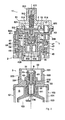
- Fig. 1 is a general cross section, showing the separation state of the connector according to first implementation embodiment of the invention.
- Fig. 2 is an enlarged cross section of the most important part of the connector structure.
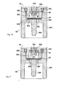
- Fig. 5 is a cross section, showing the maximum forward position during the connecting of the feed connector.
- Fig. 6 is a cross section, showing the lock position while the connector and the feed connector are connected.
- Fig. 8 is a cross section perspective view from Fig. 7, in a lock condition.
- Fig. 11 is a cross section showing the insertion condition of the pressure fluid on the example of Fig. 10.
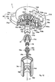
- Fig. 12 is a cross-sectioned exploded perspective view, in which the pressure regulation mechanism is implemented according to the method 2, wherein the parts are shown separately.
- Fig. 14 is a cross section exploded perspective view, in which the lower part of the pressure regulation mechanism assembled on the Fig. 12, is cross-cut within a segment of around 90 degrees of the circle centered around its axis, wherein the parts are shown separately.
- Fig. 15 is a cross section showing the maximum forward position while connecting the feed connector.
- Fig. 1 is a general cross section showing the separation state of the connector of the pressure regulation device in the first exemplary implementation of the invention
- fig. 2 is a enlarged cross section
- fig. 3 is an perspective view of the pressure vessel with implemented feed connector
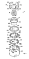
- fig. 4 is an exploded perspective view of the main parts of the ratchet mechanism
- fig. 5 is a cross section, showing the maximum forward position during the connecting of the feed connector
- fig. 6 is a cross section showing the lock position of the connector
- fig. 7 is a cross section perspective view showing the unlock condition of the connector
- fig. 8 is the same cross section perspective view as on drawing 7, however one which moved to the lock condition, and fig.
- FIG. 9 is an exploded perspective view of the pressure regulation mechanism. Still more, in the following explanations we use expressions like “up,”, “down,”, “left”, and “right,” according to the directions on the drawings, but the real installation directions may be placed not only vertically, as on fig. 1, where the axis goes up and down (it may be the opposite), but also horizontally.
- this structure is as follows. First, the tip of the feed connector 3 is inserted to the inside of the connector 2 and connected. In response to the connection of the feed connector 3, the stem valve 61 moves to the inside and starts to operate. In response to the supply of pressurized fluid, the pressure regulation mechanism 5 of the body part 11 starts to operate, and the fluid with a regulated secondary pressure starts to be released from the pressure regulation device 1.
- the key part of the operation of the structure is that, during creating the above-mentioned connection, the operation of pushing forward in order to connect the feed connector 3 is accompanied by the movement of the second ring 44 of the ratchet mechanism 4.
- the second ring 44 interlocks with a part of feed connector 3, and preserves the lock condition of the connector 2.
- the second ring 44 moves further, and causes the unlock condition.
- the unlock spring 47 coerces the connector 2 and feed connector 3 to separate.
- the pressure regulation mechanism within the body part 11 of the pressure regulation device 1, as shown on figs. 2 and 9, is equipped with a diaphragm 52, placed between cover case 51 and body case 53; an insertion member 54, connected to body case 53, through which the primary pressure fluid (liquid or gas) is being introduced; a regulation valve 55, which in response to the diaphragm 52 reduces and regulates the pressure from primary to secondary value; a first check valve 56 (low pressure check valve), preventing a leakage of a fluid; a second check valve 57 (high pressure check valve) consisting of elastic plate; and with a dust filter 58.
- a diaphragm 52 placed between cover case 51 and body case 53
- an insertion member 54 connected to body case 53, through which the primary pressure fluid (liquid or gas) is being introduced
- a regulation valve 55 which in response to the diaphragm 52 reduces and regulates the pressure from primary to secondary value
- a first check valve 56 low pressure check valve
- a second check valve 57 high pressure
- the above-mentioned first check valve 56 functions as well as a regulation valve. Moreover, the regulation valve 55 and the first check valve 56 operate in response to the deflection of diaphragm 52, and due to the mutually opposite opening/closing operation, they regulate the pressure from primary to secondary value.
- the primary pressure regulation characteristics of the regulation valve 55 and the first check valve 56 are reverse. Therefore at the diaphragm 52 the primary pressure loss within the regulation valve 55 exposed area, and the secondary pressure loss within the first check valve exposed area add toward the same direction. Due to the combination of both pressure regulation characteristics, the aberration of the secondary pressure regulation, caused by the pressure loss fluctuations occurring in response to the primary pressure fluctuations, is compensated, and the fixed secondary pressure is achieved.
- the ratchet mechanism 4 of the connector 2 is installed on the outer periphery of the insertion member 54 of the pressure regulation mechanism 5.
- This ratchet mechanism 4 as shown on fig. 2, consists of the holder body 41 and ratchet holder 42, which are fixed to the body case 53; first, second and third rings (43, 44 and 45), arranged inside the ratchet holder 42; spring holder 46, sliding freely in the axis direction; and of unlock spring 47.
- connection cylinder 32 At the predefined position at the edge of the connection cylinder 32 there are parts in a form of the pressure step 322, projecting out of the outer side. As will be discussed later, in response to the connection movement, they come into contact with the inner projections 433 of the first ring 43, and they are moved toward the direction of the axis. Moreover, there are convex members 323 in the shape of spline, protruding from the pressure step part 322 towards the interlocking projections 321. They and the interlocking projections 321 form in between them a circular space, where the second ring 44 rotates, and they interlock with the vertical groove 426 inside the lower part of the ratchet holder 42, creating a detention.
- connection mouth 31 has a pipe-like shape.
- a seal member 33 in the form of the O ring is attached to the outer periphery of the tip part.
- a nut 35 is tightened and installed to the bottom end part 311, which passes through the connection body 30.
- the stem valve 61 of the valve mechanism 6 is arranged to slide freely within the inner periphery of the intermediate step part 312.
- a valve body 63 is attached to the lower part of the stem valve 61, protruding out of the intermediate step part 312 by the O ring.
- the stem valve 61 may be contacted by the tip of a linking projection 544 (linking member) of the insertion member 54 at the hollow part of the stem valve's head.
- a spring 62 (return spring) is inserted in a squeezed position between the back face of the stem valve's head and the intermediate step part 312, and it biases toward the valve opening direction.
- the ratchet holder 42 as shown at the lower part of the fig. 4, has a tubular shape, and the top end of the cylinder part 420 is fixed to the holder body 41, as shown in the upper part of the same drawing.
- the first ring 43 (slide ring) has twelve guide projections 432 equally spaced on the outer periphery of the ring shaped base 431, and internal periphery projections 433, placed at the same positions as guide projections 432 on the inner periphery.
- the bottom and top edge surfaces of the first ring 43 are flat.
- outer periphery guide projections 432 are inserted into the second guide grooves 424 of the ratchet holder 42.
- This first ring 43 cannot rotate; the only possible movement thereof is up-and-down movement.
- the top edge of the part 322 of the connection cylinder 32 of the feed connector 3 When the top edge of the part 322 of the connection cylinder 32 of the feed connector 3 is in its upward position, it may contact the bottom surface of the internal periphery projections 433. By the pressure applied on that part (322), the first ring 43 moves upward towards the axis direction.
- the interlocking projection 321 of the connection cylinder 32 may be inserted into the vertical groove between the internal
- the second ring 44 (lock ring) has twelve guide projections 442 equally spaced on the outer periphery of the ring shaped base 441; sliding claw parts 443, endowed at the top surface with twelve equally spaced slanted surfaces; and twelve locking projections 444, equally spaced on the inner periphery.
- the second ring 44 rotates in the direction d.
- the outer periphery guide projections 442 and the inner periphery locking projections 444 are placed at the same position circumferentially. They are both joined at the lower part of the ring shaped base 441, and there is a slanted surface, high in the front of the rotation direction d, and low in the rear. Equally shaped slanted surface is on the top surface of the sliding claw parts 443, projecting towards the top surface.
- the outer periphery guide projections 442 are inserted into the second guide grooves 424 of the ratchet holder 42. They guide the sliding movement of the second ring 44 toward the axis direction. When the upward movement of the second ring 44 is long, the guide projections 442 are pulled out of the second guide grooves 424, and the second ring 44 may rotate. Due to that rotation, the bottom edge slanted surface of the guide projections 442 lower with a possibility of coming into contact with the slanted surface of the ratchet convex part 423 or the top edge slanted surface of the engaging step part.
- the rotation continues until it stops when the tip of the guide projections 442 engage the engaging step part and enter the lock state, or when the separation state is reached with guide projections 442 inserted into the guide grooves 424.
- the internal periphery locking projections 444 move between the locking interlocking projections 321 of the connection cylinder 32 of the feed connector 3, and may interlock.
- the third ring 45 (guide ring) has respectively four guide projections 452 equally spaced on the outer periphery of the ring shaped base 451, and ratchet teeth 453, with a ratchet claw-shaped slanting surface on the bottom edge surface.
- the guide projections 452 are inserted into the first guide grooves 421 of the ratchet holder 42.
- the third ring 45 may move up and down in the axis direction (rotation is not possible), and at the bottom edge position the guide projections 452 are engaged at the bottom edge part of the first guide grooves, regulated there, and separated from the second ring 44.
- the ratchet teeth 453 of the bottom edge surface come into contact with the sliding claw part 443 of the top surface of the second ring 44, and due to the contact of both slanted surfaces the second ring 44 is turned.
- Spring holder 46 is comprised of a tubular-shaped upper cylinder part 461, and a lower cylinder part 462 of a smaller diameter. Inside the holder, an unlock spring 47 is inserted in a squeezed condition, and a bottom edge outer periphery step part 463 of the upper cylinder part 461 comes into contact from above with the locking projections 444 of the second ring 44, and biases them. In that way, any free move is blocked, when the third ring 45 and the second ring 44 are separated.
- the lower cylinder part 462 of the spring holder 46 is inserted inside the first, second and third rings (43, 44 and 45), and at the bottom extends to the inner space of the ratchet holder 42. It comprises an opening at the center of the bottom surface receiving the unlock spring 47. In the opening, the connection mouth 31 of the feed connector 3 is inserted. Still more, the bottom edge part of the lower cylinder part 462 may come in contact with the inner end surface 324 of the feed connector's 3 connection body 30. Due to the connecting operation of the feed connector 3, the spring holder 46 may resist the unlock spring 47 and move upwards in the direction of the axis.
- the unlock spring 47 is a coiled spring, put between the bottom face of the flange of the connector's 2 body case 53. It presses downward the third ring 45 through the spring holder 46, and biases the feed connector 3 in the separation direction.
- the holder body 41 fixes the diaphragm 52 of the connector 2, and is attached to the body case 53. It has four fixing parts 412, equally spaced and extending upwardly, connected at the lower part ring body 411, and vertical grooves 413 placed between fixing parts 412. A fixing screw hole 415 is located on the flange part 414, projecting outwardly from the top edge of the fixing part 412. In the lower part of the outer face of the each fixing part 412, there are four pin-shaped projections 416 directed outwardly. These pin-shaped projections 416 may interlock with the L-shaped interlocking groove 422 of the ratchet holder 42, forming the assembly.
- the interlocking of the holder body 41 and ratchet holder 42 has a structure described heretofore, however this invention is in no way limited to this structure.
- an engage claw 416' (see fig. 15), interlocking to a substantially oval hole placed approximately at the center of the up-down direction of the ratchet holder's 42 first guide groove 421, is formed on the outer periphery surface of the holder body 41. By pushing it into the ratchet holder 42 without rotating the holder body 41, the engage claw 416' is removed from the oval hole.
- Such a construction is also possible.
- pressure regulation mechanism 5 By joining the body case 53 and cover case 51 by the diaphragm 52, the internal space is divided into a pressure regulation chamber 530 and an atmospheric air chamber 510.
- the diaphragm 52 may elastically deflate receiving a secondary pressure from the pressure regulation chamber 530, in response to the pressure difference with the atmospheric air chamber 510.
- the shaft 522 has a boss section 523, attached to the diaphragm 52 and located in the pressure regulation chamber 530, and a shank 524, extending from the tip of the boss section 523 toward the direction of the axis.
- a circumferential groove section 525 At the tip of the shank 524, there is a circumferential groove section 525.
- the regulation valve 55 comprising an O ring is attached.
- the first check valve 56 comprising an O ring (elastic body) is attached to the tip surface of the boss section 523.
- the support element 521 has a bolt in the middle of the flange part, which closely adheres to the diaphragm 52, passing through its center, and on the other side is joined with the shaft 522.
- one end of the pressure regulation spring 513 which is installed inside the cylinder part 511 of the cover case 51 and is used for the pressure predefining, comes into contact with the support element 521.
- the other end of the pressure regulation spring 513 comes into contact with a pressure regulation screw 512 (adjuster), which is tightened by a screw to the cylindrical part 511 in a way, that the its position regulation is possible.
- the bias force of the diaphragm 52 is regulated by the pressure regulation spring 513.
- the insertion member 54 positioned at the bottom edge has the outer periphery cylindrical part 541; the intermediate partition section 542; the linking projection 544, protruding downward from the partition section 542 and which operation is linked to the stem valve 61; and a connecting hole 543 passing through partition section on both sides of the linking projection.
- the second check valve 57 for the purpose of closing the high pressure, which can close the opening of the connecting hole 543.
- It is an elastic plate, made from e.g. rubber or sandwich plate.
- the upper end part of the cylindrical part 541 is joined in a detachable manner by the O-ring 532 to the outer periphery of the cylindrical bottom part of body case.
- a seal member of the outer periphery of the feed connector's 3 connection mouth 31 is being fit, and the pressurized fluid is introduced.
- the body case 53 is equipped with the shank 524 of the shaft 522.
- the shank 524 has an inserted partition wall 53a, which can slide freely.
- the outside and inside of that wall 53a is opened and closed by the regulation valve 55 and the first check valve 56.
- the opening and closing operation of the valves is reversed, so during the forward movement of the shank 524, the regulation valve 55 opens, and during the backward movement, the first check valve 56 opens.
- the first check valve 56 is endowed with a function, that when the pressure in the pressure regulation chamber 530 is low, and the feed connector 3 is separated, the valve is closed by the secondary pressure, and stops the backflow of the fluid.
- the linking projection 544 is fixed to the partition section 542 of the insertion member 54, and comprises a separated structure with the shank 524, moving in response to the diaphragm 52. It does not receive the deflation force of the diaphragm 52 during the connection operation.
- the filter 58 may be produced e.g. from the 85% voidage, average cell diameter 30 ⁇ m, 1 mm thick LDPE.
- the pressure vessel 12 is comprised of a vessel body 102, which at its head part has the feed connector's 3 connection body 30 attached; a storage chamber 103, storing fluid F, which is formed inside the vessel body; an air chamber 104, which is formed inside the vessel body 102, and which is mutually linked at the edge to the storage chamber, and contains compressed gas G, which creates a pressure needed to extrude the fluid F; a piston-shaped closing member 105, arranged in the storage chamber 103 to move freely, which provides a division between the fluid F and compressed gas G; and the elastic plate 108, which is compressed between the bottom part 122 of the vessel body 102, when the partition section 105 moves downward.
- the vessel body 102 is composed of the outer vessel 121; a cup body 122, which seals hermetically the bottom of the body 102; and of an inner vessel 123, which is placed inside the outer vessel.
- a notch 111 is formed, which extends in the vertical direction.
- the inner space of the inner vessel 123 and the inner space of the outer vessel 121, namely the storage chamber 103 and the air chamber 104 can communicate.
- the top edge section of the inner vessel 123 is engaged by the nut 35, and thereby fastened to the bottom edge section of the connection mouth part 31, so the inner vessel is being kept.
- a through hole 123a opens in the center of the bottom edge section of the inner vessel 123, and in response to the opening and closing of the valve mechanism's 6 stem valve, the fluid F from the storage chamber 103 can be discharged.
- the partition section 105 which is inserted in a sliding-free manner to the inner vessel 123, is composed of the body 151 and an elastic seal member 152 (O-ring).
- the outer periphery of the seal member 152 adheres tightly to the inner wall of the cylinder shape inner vessel 123, and in the upper space, i.e. the storage chamber the fluid F is being stored.
- the partition section 105 functions as a movable partition, separating the fluid F received by the storage chamber from the compressed gas received by the air chamber 104. Due to the pressure of the compressed gas operating from the back, the front fluid F is pressurized, and when the stem valve 61 opens, the fluid F is discharged.
- the filling the air chamber 104 with the compressed gas G is performed before the filling the storage chamber 103 with the fluid F with the feed connector separated.
- the partition section 105 descends.
- the partition section 105 deforms the elastic body 108, and moves further to the bottom of the storage chamber 103.
- the top end part of the notch 111 stands above the seal member 152 of the partition section 105, and the compressed gas is injected from the storage chamber into the air chamber through the notch 111.
- the stem valve 61 opens again and the compressed gas is exhausted from the storage chamber 103.
- the partition section 105 returns to the sealed condition of the storage chamber 105. It moves further forward to the top end of the inner vessel 123 due to the exhaustion of the gas.
- the air chamber 104 is filled with the compressed gas G.
- the fluid F is injected into the storage chamber 103 through the stem valve 61.
- the pressure vessel can contain compressed gas in the form of a fluid.
- the inner vessel is not used and the gas is stored directly in the outer vessel.
- the fluid may be enriched with some propellant, being of so called "aerosole structure".
- connection mouth part 31 of the feed connector 3 is inserted to the insertion member 54 of the connector 2.
- valve mechanism 6 of the feed connector 3 opens, the fluid duct is connected and the supply is possible; the ratchet mechanism 4 is locked.
- the step part 463 of the ratchet mechanism's 4 spring holder 46 contacts and produces pressure on the locking projections 444 of the second ring 44.
- Guide projections 432 and 442 of the first ring 43 and second ring 44 are in the second guide groove 424 of the ratchet holder 42, and the second ring 44 cannot rotate.
- the descended position of the third ring 45 is a regulated position. In this condition, the first check valve of the regulation mechanism 5 closes, and the stem valve 61 of the feed connector 3 is closed as well.
- the interlocking projections 321 for locking the connection cylinder 32 pass through the vertical grooves of the first ring 43 and second ring 44, as shown on fig. 7.
- the bottom end of the spring holder 46 contacts the inner end surface 324 of the feed connector 3, and is pushed upward.
- the pressure step 322 contacts the bottom face of the first ring 43 and pushes it upward.
- the second ring 44 also rises, comes into contact with the bottom face of the third ring 45, stopped at the bottom end of the first guide groove 421.
- the third ring 45 is raised as well.
- the guide projection 442 of the second ring 44 leaves the top edge of the second guide groove 424 of the ratchet holder 42, and can be turned.
- the tips of the guide projections 442 at the bottom end of the second ring 44 move from the second guide groove 424 position onto the slanted surface of the ratchet convex part 423.
- the second ring 44 descends further downward, and rotates further along the slant.
- Fig. 6 is a cross section of that locked condition.
- the pressure regulation mechanism 5 operates and the fluid adjusted to the set pressure value is supplied from the body part's 11 side to the exhaust opening 514.
- the first ring 43 and the second ring 44 move upwardly, and the bottom end part of the second ring 44 separates from the engaging step, so the rotation is possible.
- the second ring 44 turns by the slanting surface of the ratchet teeth 453 of the third ring 45.
- the slanted surface of the guide projections 442 of the second ring 44 comes into contact with the slanted surface extending from the engage step of the ratchet convex part 423 to the second guide groove 424. By this contact, the second ring 44 turns further toward the rotation direction d.
- the pressure regulation mechanism by the pressure regulation of the regulation valve 55 and the check valve 56, in response to the movement of the diaphragm 52, regulates the primary pressure to the set secondary pressure value, regardless of the primary pressure value, what is discussed below in details.
- the pressure regulation characteristics of the regulation valve 55 and the first check valve 56 are reversed in order to change the primary pressure.
- the secondary pressure increases when regulated by the regulation valve 55, and decreases when regulated by the first check valve 56.
- the pressure loss produced at the tip of the shank 524 by the exposed area of the regulation valve 55 and being an effect of the primary pressure, and the pressure loss produced at the boss part 523 by the exposed area of the first check valve 56 and being an effect of the secondary pressure, together operate thereupon the shaft 533 is moving in the same backward direction. Therefore due to the combination of their both characteristic, the secondary pressure fluctuation is fixed regardless the fluctuation of the primary pressure.
- the pressure regulation characteristics of the primary pressure takes into account the aberration due to receiving the pressure of the regulation valve 55 versus the gradual drop of the primary pressure within the pressure vessel 12, when the fluid is supplied from it.
- the first check valve opens and closes in the opposite direction than the regulation valve 55.
- the pressure loss of check valve 56 has the same direction as the pressure loss of the regulation valve 55, and nearly reversed characteristics. Contrary to that, the pressure regulation characteristics of the first check valve 56 is that it restraints the secondary pressure, when the primary is low; especially when the primary pressure equals 0 it is closed and prevents the backflow of the fluid; it is unlocked with the increase of the primary pressure, so when the primary pressure rises, the secondary does so as well. Therefore it possesses a characteristic reverse to the regulation valve 55.
- Both pressure regulation characteristics operate to the same direction to the shaft 522.
- the pressure regulation characteristics which is a product of combination of both reversed characteristics of regulation valves 55 and 56, allows for obtaining a fixed secondary pressure against the fluctuation of the primary pressure.
- the two pressure regulation characteristics that due to the pressure loss effecting by the regulation valve 55, the secondary pressure rises, and that due to the pressure effecting by the check valve 56 the secondary pressure is lowered - are combined.
- Such combined characteristics are appropriately balanced, and the fixed secondary pressure is maintained reliably by this simple structure.
- the first and second check valves respectively 56 and 57, function as backflow preventing check valves in order to prevent a leakage of the fluid.
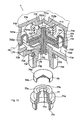
- Fig. 12 is a sectional cross section exploded perspective view of the pressure regulation mechanism, from which a segment of about 90 degrees of the circle centered around the mechanism Y axis has been cut out.
- Fig. 13 is an enlarged sectional cross section of the upper part of the pressure regulation mechanism 7 from fig. 12.
- Fig. 14 is a part cross section exploded perspective view, in which the lower part of the pressure regulation mechanism 7 assembled on fig. 12, is cross-cut within a segment of around 90 degrees of the circle centered around its axis Y. Moreover, the parts are shown separately.
- the pressure regulation mechanism 7 has a housing 70, comprised of a body case 73, a cover case 71, and a cylindrical insertion member 74, installed on the body case 73.
- the body case 73 and the cover case 74 have respectively bulge parts 73b and 71 b, and flanges 73a and 71 a of the same shape on the outer periphery.
- On the bulge 73b there is a through hole 73d, matching the axis Y (figs 13 and 14).
- the flanges 73a and 71 a of the body case 73 and the cover case 71 abut one another and are joined for example by a screw (not shown on the figure).
- a hollow part 73c On the abutting surface 70a (fig. 12) of the body case's 73 flange 73a, there is formed a hollow part 73c. It is formed on the whole circumference, inside the flange 73a.
- a diaphragm 72 In this hollow part 73a a diaphragm 72 is placed, and by connecting flanges 73a and 71 a, the diaphragm 72 between them is pressed and fixed. Since by creating the hollow part 73c the diaphragm 72 is secured at a fixed position, the possibility that due to a distorted assembly of the diaphragm during the above mentioned connecting, pressing and fixing, there might occur leakages of the fluid, is decreased.
- the diaphragm 72 is substantially a flat, plate-shaped elastic part, made for example from rubber, and has a circle-shaped curve deflected part 72a (fig. 13) with the axis Y as its center. Moreover, in the part of the diaphragm 72 corresponding to the axis Y there is a round opening 72b (fig. 13). There is a support element 721 from the diaphragm's 72 curve deflected part 72a to the inside top face.
- the support element 721 is provided with a flat plate 721 a, contacting with the upper face of the diaphragm 72 (drawing 13), and a projecting part 721b, projecting upwardly from the flat plate 721 a. It would be desirable, if the support element 721 were constructed from a light material, like for example polyoxymethylene (POM), but metal is also acceptable.
- the upper face of the projecting part 721 b is flat. Further, in the projecting part 721 b there is formed an internal thread, parallel to the axis Y (fig. 13).
- a convex portion 711 In the inner surface of the cover case's 71 bulge part 71 b, there is formed a convex portion 711, in a position corresponding to the projecting part 721 b.
- the tip of the convex portion 711 i.e. the bottom face, has the same flat shape as the top face of the support element 721.
- a small opening 711 a In the center of the convex portion 711, there is a small opening 711 a (fig. 13) to the outer part. Since within the outer part there is usually the atmospheric air pressure, the space inside the bulge 71 b is preserved by the atmospheric air pressure, becoming an atmospheric air chamber 710.
- an extension part 71c bulging to the side from the bulge part 71 b (fig. 12).
- a pipe 715 with an exhaust opening 714 extending from the extension part 71c to the outside.
- a column-shaped space 710a formed by the partition wall 71d, connected to the exhaust opening 714.
- a substantially column-shaped space 730a formed by the partition wall 73d.
- the end surface 73d' of the partition wall 73d (fig. 13) is shown.
- the cylinder member 731 is sized in the longitudinal direction as to create a gap between its bottom edge and the inner surface of the bulge part 73b (figs. 13, 14). It becomes a duct guiding the fluid passing through the groove 73e to the exhaust opening 714. In other words, the duct becomes an exit for exhausting the pressurized fluid, stored in the pressure regulation chamber described below.
- the cylinder member 731 is made for example from the polyoxymethylene. Still further, however in this embodiment, the extending part 71 c, the exhaust opening 714 and the pipe 715 were formed, there is no need to limit oneself in such a way within the scope of the invention, and one may consider a different structure supplying a fluid stored within the pressure regulation chamber outside (e.g. to the fuel cell), for example an extending part, an exhausting opening and a pipe in the body case 73.
- a space namely a pressure regulation chamber 730.
- a circumferential groove 725 (fig. 13), with a regulation valve 75 attached in it. This valve is driven up and down by the diaphragm 72. It cuts off and enables the fluid flow passing between the shank 722c and the through hole 73d, and regulates the fluid pressure in the pressure regulation chamber 730.
- the diaphragm 72 is of elastic nature, when the shank 722c, to which the shank 522, namely regulation valve 75, is attached, leans due to vibrations of the diaphragm 72, the valve seat at the bottom face of the extending part 73b is wounded, and there is a danger of the pressure control malfunction. Therefore the outer periphery of the flat plate 722a of the shaft 722 is leaned and supported by the partition wall 73d of the body case 73 and the inner periphery surface of the extending part 73b. By doing that in a position relatively close from the diaphragm 72, it is possible to decrease the lean of the shank 722c.
- a passing groove 732 through which passes the fluid, which previously had passed the above-mentioned space in between.
- the groove is placed in the position between the opening and the shank 722c, as to extend from the inside to the outside of the space. Due to such a construction, if the pressure of a fluid supplied from the pressure vessel is low, by the opening of the regulation valve 75 and the downwardly move of the shaft 722, the bottom face of the flat plate 722a of the shaft 722 and the top face of the body case 73 contact, and any hindrance in the fluid flow can be prevented.
- the passing groove 732 is placed in an opposite position between the opening and the shank 722c, due to the broad scope of the fluid flow in the pressure regulation chamber 730, it is more difficult for a gas in the pressure regulation chamber 730 to remain there, the causes for abnormal vibrations of the diaphragm 72 (chattering; below referred to as "chattering") lessen, and the operation of the pressure regulation mechanism 7 is more stable.
- the passing groove was created as described heretofere, but it may as well be put in the body case 53 of the pressure regulation chamber 5 of the previously described embodiment.
- the pressure regulation chamber 730 is substantially formed only by the moving space of the diaphragm 72 and the shaft 722, and the flow duct.
- the pressure control of the compressed fluid e.g. gas
- a non-compressed fluid, as liquid since it is hard for the vibrations to occur, it is possible to decrease the volume of pressure regulation chamber 730, and make one (pressure regulation chamber 730) as previously described.
- the pressure regulation chamber 730 may be redesigned conveniently as to match the fluid stored in it.
- a circular wall 73f In the extending part 73b of the body case 73, there protrudes downwardly a circular wall 73f, as to surround the tip part of the shank 722c. At the outer periphery of its base there is a round groove 73f (fig. 13), in which a O-ring 733 is attached. On the outer periphery of the circular wall 73f there may be (not shown on the figure) a thread, as to fit the insertion member 74.
- the taper is designed in such a manner that there is a sealing action provided by the seal member 33 before the stem valve 61 of the valve mechanism 6 opens during the connection of the feed connector 3. Further, the angle made by the inner periphery surface and partition part 742 becomes a C surface 744. Owing to this, the "dead space" of the introducing member 74 is reduced, and the fluid leakage during connecting and disconnecting of the feed connector 3 is reduced as well. Still more, with this implementation embodiment, there has been created the above mentioned taper and the C surface, but they may as well be formed in the introducing member 54 of the pressure regulation mechanism of the previously described implementation embodiment.
- a filter 78 Between the partition section 742 and the extending part 73b there are arranged (from the top) a filter 78, a coupler 77, a helical compression spring 79 (referred to below as the "spring"), and a plug 76.
- the coupler 77 has generally a cylindrical shape and is provided with an upper wall 77a, made for example from polyoxymethylene. In the center of the upper wall 77a of the coupler 77 there is an opening 77b, and between the upper wall 77a and the bottom end 77c there is formed a circle-shaped flange 77d, extending outwardly.
- the filter 78 has a shape of a circular wall 78b hanging down on the outer periphery of the circle-shaped plate part 78a, and it is mounted on the upper wall 77a of the coupler 77.
- the fluid-passing area of the fluid passing through the filter 78 may vary according to the width of the opening 77b. When the area is wide, the flow speed of the fluid accelerates. Therefore, for example at times of the initial stage, when there is no fuel (fluid) in the fuel cell, the fluid may be supplied rapidly.
- the filter 78 is shaped in the described way, but the invention is not limited to this example.
- the filter may be for example plate-shaped element.
- the material of the filter 78 is the same as the material of the filter 58.
- the plug 76 is a pin-shaped plug made from stainless steel or polyoxymethylene. Near the top of the plug there is a round plate-shaped flange 76a.
- the upper shaft 76b projecting upwardly from the flange 76a, has a diameter that enables inserting thereof inside the spring 79.
- the lower shaft 76c projecting downwardly from the flange 76a, converges toward the bottom end of the flange 76. In other words it has tip narrowing shape with taper.
- This lower shaft 76c becomes the linking projection 76c, functioning as a linking member operating with the stem valve 61.
- the linking projection 76c has a regulation valve 75 and constitutes a structure separated from the shank 722c, moving in response to the diaphragm 72, so the diaphragm 72 does not receive any deviation force during the connection operation.
- the spring 79 and the plug 76 are hold between the upper wall 77a of the coupler 77 and the partition section 742 of the insertion member 74. Then the flange 76a of the plug 76 is urged below the spring 79, and the O-ring 761 is pressed between the flange 76a and the partition section 742.
- the O-ring 761 adheres to the partition section 742 and the flange 76a, due to the biasing force of the spring.
- the pressurized fluid inside the pressure regulation mechanism 7 is prevented from leaking outside from between the linking projection 76c of the flange 76 and the opening 743 of the partition section 742. Since such a structure is a structure independent from the regulation valve 725, it is not influenced by the secondary pressure of the fluid or by the secondary pressure setting.
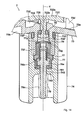
- Fig. 15 is a cross section of the pressure regulation mechanism 7 in the state of being connected to the feed connector 3.
- Fig. 15 shows the cross-section of the most important part.
- the plug 76 is pressed upwardly by the stem valve 61.
- the plug 76 namely the linking projection 76c and the regulation valve 75, together with the shank 722c, moving with the diaphragm 72, are installed separately, the force of the upward pressure do not effect the diaphragm 72 and the pressure regulation function.
- the opening 743 of the introducing member 74, tightly sealed by the O-ring 761, is opened, and the pressurized fluid passes successively through the opening 743, the groove 77e inside the coupler 77 and the filter 78. Since in the connection initial state of the feed connector 3, the pressure of the fluid within the pressure regulation chamber 730 is low, the diaphragm 72 is biased downwardly by the pressure regulation spring 713. Consequently, because the regulation valve 75 sealing the through hole 73d of the body case 73 moves downwardly as to separate from the through hole 73d, the sealing is removed from it.
- the diaphragm 72 is set to achieve the fixed secondary pressure by the action of the pressure regulation spring 713, when the pressure of the supplied fluid is for example 900 Kpa-1 Mpa.
- the pressure regulation spring 713 presses the diaphragm 72 upwardly, opposing the biasing force of the pressure regulation spring 713.
- the shank 722c of the shaft 722 moves upwardly.
- the regulation valve 75 seals the through hole 73d of the body case 73, and more of the pressurized fluid is prevented from entering the pressure regulation chamber 730.
- the diaphragm 72 constantly moves up and down in reaction to the fluid pressure's fluctuation.
- the moving distance is extremely short, for example about 0.3 mm
- the width of the gap between the above mentioned gap G namely the top face of the projecting part 721 b of the support element 721, and the bottom face of the convex portion 711 of the cover case 71, is kept substantially fixed.
- the regulation valve 75 is shown as to contact the body case 73 when the pressurized fluid flows, but as a matter of fact the gap between them is extremely small, and the passage of the pressurized fluid is possible.
Landscapes
- Engineering & Computer Science (AREA)
- Mechanical Engineering (AREA)
- General Engineering & Computer Science (AREA)
- Physics & Mathematics (AREA)
- Chemical & Material Sciences (AREA)
- Combustion & Propulsion (AREA)
- Fluid Mechanics (AREA)
- General Physics & Mathematics (AREA)
- Automation & Control Theory (AREA)
- Filling Or Discharging Of Gas Storage Vessels (AREA)
- Control Of Fluid Pressure (AREA)
- Measuring Fluid Pressure (AREA)
Priority Applications (1)
| Application Number | Priority Date | Filing Date | Title |
|---|---|---|---|
| EP20090015824 EP2172827A3 (de) | 2004-09-14 | 2005-09-12 | Druckregler |
Applications Claiming Priority (3)
| Application Number | Priority Date | Filing Date | Title |
|---|---|---|---|
| JP2004266463 | 2004-09-14 | ||
| JP2005243658A JP2006114017A (ja) | 2004-09-14 | 2005-08-25 | 調圧装置 |
| PCT/JP2005/017207 WO2006030923A1 (ja) | 2004-09-14 | 2005-09-12 | 調圧装置 |
Publications (2)
| Publication Number | Publication Date |
|---|---|
| EP1798623A1 true EP1798623A1 (de) | 2007-06-20 |
| EP1798623A4 EP1798623A4 (de) | 2009-10-28 |
Family
ID=36060168
Family Applications (2)
| Application Number | Title | Priority Date | Filing Date |
|---|---|---|---|
| EP05785807A Withdrawn EP1798623A4 (de) | 2004-09-14 | 2005-09-12 | Druckregler |
| EP20090015824 Withdrawn EP2172827A3 (de) | 2004-09-14 | 2005-09-12 | Druckregler |
Family Applications After (1)
| Application Number | Title | Priority Date | Filing Date |
|---|---|---|---|
| EP20090015824 Withdrawn EP2172827A3 (de) | 2004-09-14 | 2005-09-12 | Druckregler |
Country Status (5)
| Country | Link |
|---|---|
| US (1) | US20080314462A1 (de) |
| EP (2) | EP1798623A4 (de) |
| JP (1) | JP2006114017A (de) |
| KR (1) | KR20070057248A (de) |
| WO (1) | WO2006030923A1 (de) |
Cited By (1)
| Publication number | Priority date | Publication date | Assignee | Title |
|---|---|---|---|---|
| US8256740B2 (en) | 2006-08-29 | 2012-09-04 | Canon Kabushiki Kaisha | Connection mechanism for fluid pipings, manufacturing method for the same, and fuel cell system including connection mechanism for fluid pipings |
Families Citing this family (6)
| Publication number | Priority date | Publication date | Assignee | Title |
|---|---|---|---|---|
| EP2565468B1 (de) * | 2011-09-01 | 2015-07-29 | Carl Freudenberg KG | Ventilanordnung |
| CN102563346B (zh) * | 2012-02-07 | 2014-09-03 | 内蒙古物通天下网络科技有限责任公司 | 基于二维码的气瓶防偷倒气系统 |
| DE202017104079U1 (de) * | 2017-07-07 | 2017-08-21 | Samson Ag | Stellantrieb für Prozessventile |
| GB201711670D0 (en) * | 2017-07-20 | 2017-09-06 | Qinov8 Uk | Safety valve |
| KR20220002204U (ko) | 2021-03-08 | 2022-09-15 | 문영택 | 산소 용접기용 초소형 압력조정기 |
| WO2025031682A1 (en) * | 2023-08-10 | 2025-02-13 | Micro Matic A/S | A pressure regulation device |
Family Cites Families (21)
| Publication number | Priority date | Publication date | Assignee | Title |
|---|---|---|---|---|
| US2005445A (en) * | 1931-03-16 | 1935-06-18 | Alfred H Wiedhofft | Regulator |
| US3229716A (en) | 1962-08-27 | 1966-01-18 | Fisher Governor Co | Cylinder valve unit |
| FR1550346A (de) | 1967-11-06 | 1968-12-20 | ||
| US3590860A (en) | 1969-07-31 | 1971-07-06 | Bernzomatic Corp | Pressure regulator valve for l. p. cartridges |
| US3693652A (en) * | 1970-03-04 | 1972-09-26 | Gurtner Sa | Liquefied gas tank distributor valve units |
| DE2648110A1 (de) * | 1976-10-23 | 1978-04-27 | Schulz & Rackow | Steckaufsatz fuer anschlussarmaturen mit absperrbarem durchlass |
| US4225060A (en) * | 1978-12-29 | 1980-09-30 | Security Plastics, Inc. | Continuous pumping system |
| JPS55141807A (en) * | 1979-04-23 | 1980-11-06 | Toshiba Corp | Antenna unit for transponder |
| US4324269A (en) * | 1980-07-15 | 1982-04-13 | Baranowski Jr Frank | Pressure regulator |
| DE3241843C2 (de) * | 1982-11-12 | 1986-03-20 | Schulz + Rackow GmbH, 3554 Gladenbach | Verschluß für ein Gasflaschenventil |
| JPH04409Y2 (de) * | 1985-07-30 | 1992-01-08 | ||
| JPS63179513A (ja) * | 1987-01-21 | 1988-07-23 | Nec Corp | 非混和性化合物半導体四元混晶の製造方法 |
| JPH0454488Y2 (de) * | 1987-05-09 | 1992-12-21 | ||
| JPH03117857A (ja) * | 1989-09-29 | 1991-05-20 | Aisin Seiki Co Ltd | 往復動機械 |
| JPH0355731U (de) * | 1989-10-03 | 1991-05-29 | ||
| US5178799A (en) * | 1991-01-07 | 1993-01-12 | Wilshire Partners | Carbonated beverage dispensing apparatus |
| US5144708A (en) * | 1991-02-26 | 1992-09-08 | Dielectrics Industries | Check valve for fluid bladders |
| US5265844A (en) * | 1992-11-02 | 1993-11-30 | Westfall Randell W | Receptacle valve assembly and seal |
| DK46794A (da) * | 1994-04-22 | 1995-10-23 | Kosan Teknova As | To-trins reduktionsventil til luftformige medier |
| US6105598A (en) | 1996-06-14 | 2000-08-22 | United States Filter Corporation | Low capacity chlorine gas feed system |
| JP2002157022A (ja) * | 2000-11-21 | 2002-05-31 | Corona Corp | 給湯機に用いる逆止弁付き減圧弁装置 |
-
2005
- 2005-08-25 JP JP2005243658A patent/JP2006114017A/ja active Pending
- 2005-09-12 EP EP05785807A patent/EP1798623A4/de not_active Withdrawn
- 2005-09-12 WO PCT/JP2005/017207 patent/WO2006030923A1/ja not_active Ceased
- 2005-09-12 KR KR1020077008568A patent/KR20070057248A/ko not_active Ceased
- 2005-09-12 US US11/575,277 patent/US20080314462A1/en not_active Abandoned
- 2005-09-12 EP EP20090015824 patent/EP2172827A3/de not_active Withdrawn
Cited By (1)
| Publication number | Priority date | Publication date | Assignee | Title |
|---|---|---|---|---|
| US8256740B2 (en) | 2006-08-29 | 2012-09-04 | Canon Kabushiki Kaisha | Connection mechanism for fluid pipings, manufacturing method for the same, and fuel cell system including connection mechanism for fluid pipings |
Also Published As
| Publication number | Publication date |
|---|---|
| JP2006114017A (ja) | 2006-04-27 |
| US20080314462A1 (en) | 2008-12-25 |
| EP1798623A4 (de) | 2009-10-28 |
| WO2006030923A1 (ja) | 2006-03-23 |
| KR20070057248A (ko) | 2007-06-04 |
| EP2172827A2 (de) | 2010-04-07 |
| EP2172827A3 (de) | 2010-04-21 |
Similar Documents
| Publication | Publication Date | Title |
|---|---|---|
| US6832704B2 (en) | Metering valve for aerosol container | |
| JP4699730B2 (ja) | ロック機構付コネクタ構造 | |
| CN1839068B (zh) | 用于充填隔离包气雾阀上袋的装置和方法 | |
| JP4713676B1 (ja) | 連結装置 | |
| US4600123A (en) | Propellant augmented pressurized gas dispensing device | |
| KR20180011745A (ko) | 비-충전 에어로졸 밸브 | |
| EP1798623A1 (de) | Druckregler | |
| US6299024B1 (en) | Valve assembly for dispensing container | |
| US5131625A (en) | One-time use disposable bottle valve | |
| CN100565011C (zh) | 带锁定机构的连接器结构 | |
| CN100559317C (zh) | 调压装置 | |
| KR101051092B1 (ko) | 가스용기 탭의 안전밸브 | |
| JP7450450B2 (ja) | 吐出容器 | |
| JP4714008B2 (ja) | 圧力調整器 | |
| JP6523739B2 (ja) | 弁装置 | |
| JP2006153160A (ja) | 逆止弁構造および逆止弁用弁体並びに逆止弁用弁体の製造方法 | |
| US12409959B2 (en) | Filling head for a device for dispensing a fluid product having a valve | |
| US20170240344A1 (en) | Fuel canisters and fuel canister valve assemblies | |
| JP2007127265A (ja) | 流体供給システム及び流体継手 | |
| US6467515B1 (en) | Gas container | |
| JP7186577B6 (ja) | 吐出容器 | |
| JP2022011331A (ja) | 吐出器 | |
| JPH08143077A (ja) | エアゾ−ル容器用バルブハウジング | |
| JPH054671A (ja) | エアゾールバルブおよびその組立方法 |
Legal Events
| Date | Code | Title | Description |
|---|---|---|---|
| PUAI | Public reference made under article 153(3) epc to a published international application that has entered the european phase |
Free format text: ORIGINAL CODE: 0009012 |
|
| 17P | Request for examination filed |
Effective date: 20070416 |
|
| AK | Designated contracting states |
Kind code of ref document: A1 Designated state(s): AT BE BG CH CY CZ DE DK EE ES FI FR GB GR HU IE IS IT LI LT LU LV MC NL PL PT RO SE SI SK TR |
|
| DAX | Request for extension of the european patent (deleted) | ||
| A4 | Supplementary search report drawn up and despatched |
Effective date: 20090928 |
|
| 17Q | First examination report despatched |
Effective date: 20100315 |
|
| STAA | Information on the status of an ep patent application or granted ep patent |
Free format text: STATUS: THE APPLICATION IS DEEMED TO BE WITHDRAWN |
|
| 18D | Application deemed to be withdrawn |
Effective date: 20120403 |