EP1798633A1 - System mit einer Projektierungsvorrichtung und einer Mensch-Maschine-Schnittstelle - Google Patents
System mit einer Projektierungsvorrichtung und einer Mensch-Maschine-Schnittstelle Download PDFInfo
- Publication number
- EP1798633A1 EP1798633A1 EP05025358A EP05025358A EP1798633A1 EP 1798633 A1 EP1798633 A1 EP 1798633A1 EP 05025358 A EP05025358 A EP 05025358A EP 05025358 A EP05025358 A EP 05025358A EP 1798633 A1 EP1798633 A1 EP 1798633A1
- Authority
- EP
- European Patent Office
- Prior art keywords
- machine interface
- man
- input device
- input
- inputs
- Prior art date
- Legal status (The legal status is an assumption and is not a legal conclusion. Google has not performed a legal analysis and makes no representation as to the accuracy of the status listed.)
- Ceased
Links
Images


Classifications
-
- G—PHYSICS
- G06—COMPUTING OR CALCULATING; COUNTING
- G06F—ELECTRIC DIGITAL DATA PROCESSING
- G06F3/00—Input arrangements for transferring data to be processed into a form capable of being handled by the computer; Output arrangements for transferring data from processing unit to output unit, e.g. interface arrangements
- G06F3/01—Input arrangements or combined input and output arrangements for interaction between user and computer
- G06F3/048—Interaction techniques based on graphical user interfaces [GUI]
- G06F3/0487—Interaction techniques based on graphical user interfaces [GUI] using specific features provided by the input device, e.g. functions controlled by the rotation of a mouse with dual sensing arrangements, or of the nature of the input device, e.g. tap gestures based on pressure sensed by a digitiser
- G06F3/0488—Interaction techniques based on graphical user interfaces [GUI] using specific features provided by the input device, e.g. functions controlled by the rotation of a mouse with dual sensing arrangements, or of the nature of the input device, e.g. tap gestures based on pressure sensed by a digitiser using a touch-screen or digitiser, e.g. input of commands through traced gestures
- G06F3/04886—Interaction techniques based on graphical user interfaces [GUI] using specific features provided by the input device, e.g. functions controlled by the rotation of a mouse with dual sensing arrangements, or of the nature of the input device, e.g. tap gestures based on pressure sensed by a digitiser using a touch-screen or digitiser, e.g. input of commands through traced gestures by partitioning the display area of the touch-screen or the surface of the digitising tablet into independently controllable areas, e.g. virtual keyboards or menus
Definitions
- the invention relates to a system with a projecting device and a man-machine interface having an input device and an output device.
- a touch screen offers excellent HMI (human-machine interface) characteristics because it performs actions directly on the touchscreen display objects and allows both input and output from this device.
- HMI human-machine interface
- conventional touch screens are nowadays usually very time-consuming realized with individual discrete electrical components. In the finished state they are very inflexible and often have to be completely rebuilt in case of technical changes. However, this is also due to high production costs. Since a touchscreen is very often connected to freely programmable programmable logic controllers, there is a direct contradiction here.
- Touchscreen applications are optimized for a particular hardware software platform. Often, applications developed for a particular touchscreen display configuration will not work correctly with other graphics settings. The graphical configuration of the touchscreen display is fixed and can not be changed flexibly.
- the invention is based on the object to provide a way to flexibly project a human-machine interface.
- a system comprising a projecting device and a man-machine interface with an input device and an output device, wherein the projecting device is provided for the configuration of the man-machine interface, wherein static Information can be visualized with a first means, wherein dynamic output information can be displayed with the output device, wherein inputs can be detected by the input device, wherein the projecting device, the linkage of the static information, the dynamic output information and the inputs is configured such that, as a result the static information based layout and data for the configuration of the input device and the output device can be provided.
- the invention is based on the idea of displaying the display of an input device by means of replaceable static information and dynamic output information, wherein in particular the layout of the display is represented by the static information and the feedback of inputs by the dynamic output information.
- a system with a projecting device and a man-machine interface with an input device and an output device is designed such that the projecting device is provided for the configuration of the man-machine interface and the linking of the static information, the dynamic output information and the inputs are executed via the input device are provided.
- This configuration is executed so as to provide, as a result, a static information based layout and data for configuring the input device and the output device. Therefore, the input with the input device is detectable.
- the system according to the invention makes it possible to simplify the provision of inputs that are executed by a man-machine interface. It is possible to use such an input device in several areas and to reduce the cost of manufacturing or rebuilding the input device because the display capability of the man-machine interface can be changed flexibly.
- the input device is a touchscreen.
- a touchscreen offers excellent features in terms of the HMI (Human Machine Interface).
- HMI Human Machine Interface
- This advantageous embodiment of the invention thus makes it possible that the display options of a touch screen are flexibly changeable, so that the touch screen has a certain adaptability. For example, buttons, buttons, lamp assemblies, etc., displayed on the touchscreen can be flexibly changed without much effort.
- the layout is provided as a print image on the first means and the man-machine interface has a receiving device for receiving the first means.
- the layout is printed by a conventional printer on a printable material.
- a suitable material may e.g. Be printing paper or foil.
- the material may also be a metal plate or plastic plate, etc.
- the material may simply be incorporated in the input device by means of the recording device as a display, the recording device being a pure mechanism, e.g. a clamp.
- the display capability of the input device is therefore flexibly changeable or replaceable. In the change, the display is replaced without disassembling the man-machine interface or the input device. Accordingly, display configurations such as buttons, buttons, lamp assemblies, etc. can be changed easily.
- the output device is a projection laser.
- This projection laser can project laser beams. This allows dynamic output information z. B. generated as feedback to the inputs. If an input is recognized by the input device, it is thus possible, for example, for a signal light with respect to the executed input with the output device to give the user a feedback.
- other dynamic information such as moving or flashing texts as auxiliary information for inputs, can be displayed.
- the laser beams projected by the projection laser are colored.
- the input device comprises means for generating a vibration signal, in particular as a response for confirmation of inputs.
- the strength or the frequency of the vibration can be adjusted according to a further advantageous embodiment of the invention if necessary.
- the vibration signal may in particular also be an acoustic signal. Then the feedback of the inputs is also felt by a user and possibly audible.
- the input device comprises at least one interface for connecting an external device. So you can combine this input device with other devices and expand the uses.
- an external device By means of standard interfaces such as RS485, Ethernet and USB can be connected to the input device, for example, a control panel (operator panel or keyboard) as an extension input device.
- the system 1 shows a system with a configuration device 3 and a human-machine interface 5.
- the system 1 provides inputs via the man-machine interface 5.
- As a configuration computer is provided for the configuration of the man-machine interface 5.
- the graphic data 12 and the function data 13 of the man-machine interface 5 are configured in the configuration device 3, ie the layout of the display 16 of the man-machine interface 5 and the input functions associated with the layout are configured.
- the function data 13 When configuring the function data 13, the coordinates of input functions and their feedback are also provided.
- dynamic information eg. B. in the form of feedback by means of projected laser beams projected.
- the graphic data is forwarded to a conventional printer 10, whereas the functional data is stored in the man-machine interface 5 or in a portable memory 14, eg a CD, a floppy disk or a USB memory.
- the printer 10 the layout is printed on a printing paper 11, then the printed printing paper 11 can be used as a display 16 in the man-machine interface 5.
- the inputs, which are executed according to the layout on the man-machine interface 5, are detectable as in conventional human-machine interfaces. This provides a man-machine interface 5 whose display 16 is flexible and inexpensive to use. Such a man-machine interface 5 allows use in several areas.
- the man-machine interface 5 shows a human-machine interface 5 having a touch screen 2 for input, a display surface 4 for visualization of the display 16 of the touch screen 2 and an electronic unit 15 for storing and evaluating the function data 13.
- the display surface 4 can be a printing paper 11 or a film which can be easily inserted or removed under the touch screen 2 without dismantling the man-machine interface 5.
- the man-machine interface 5 comprises a bracket 7 as a receiving device and as a damping means to fix the display surface 4.
- the display structure (layout) of the touchscreen 2, such as buttons, buttons, lamp arrangements, is visualized printed on the display surface 4 (FIG. 3).
- the human-machine interface 5 also comprises a projection laser 17, which can project colored laser beams on the display surface 4. By means of the laser beams dynamic information, such as indicator lights, can be displayed on the display 16 of the touch screen 2 to indicate a response or confirmation of inputs.
- the man-machine interface 5 has a vibration technology to stimulate haptic feedback.
- the human-machine interface 5 is equipped with a vibration module 8 and a vibration plate 18.
- the vibration module 8 calculates an input signal, a frequency signal, accordingly, a vibration on the vibration plate 18 can be generated.
- the frequency of the signal is adjustable, whereby an acoustic signal can be generated.
- the man-machine interface 5 comprises an interface 9 for connecting external devices / devices. By means of this interface 9, an external device, such as a mouse, can be connected to the man-machine interface 5 as an extension input device.
- the layout of the touch screen 2 is shown on a printing paper 11 according to FIG. 3, furthermore a colored laser beam is projected by the projection laser 17 onto the printing paper 11.
- the laser beam is used for. B. as feedback or confirmation info for an input that was executed via the touch screen 2.
- FIG. 4 shows an example of the display 22 of a human-machine interface with touchscreen. If you press the key 19, a signal light 20 is generated at this key 19 and thus a visual confirmation of this input by the projected laser beam.
- This can z. B. be a colored status indicator.
- a dynamic or flashing display (text or image) 21 can be displayed as dynamic help information on the layout.
- the human-machine interface also has feedback in the form of vibration.
- the key 19 vibrates differently with each touch.
- the button 23 vibrates continuously when touched.
Landscapes
- Engineering & Computer Science (AREA)
- General Engineering & Computer Science (AREA)
- Theoretical Computer Science (AREA)
- Human Computer Interaction (AREA)
- Physics & Mathematics (AREA)
- General Physics & Mathematics (AREA)
- Position Input By Displaying (AREA)
- User Interface Of Digital Computer (AREA)
Abstract
Description
- Die Erfindung betrifft ein System mit einer Projektierungsvorrichtung und einer Mensch-Maschine-Schnittstelle, die eine Eingabevorrichtung und eine Ausgabevorrichtung aufweist.
- Als Eingabevorrichtung bietet ein Touchscreen (Berührungsbildschirm) hervorragende Eigenschaften im Sinne von HMI (Human-Maschine Interface) an, weil man Aktionen direkt auf Objekten der Anzeige des Touchscreens ausführt und sowohl Eingaben als auch Ausgaben über dieses Gerät möglich sind. Aber konventionelle Touchscreens werden heute meist sehr zeitaufwendig mit einzelnen diskreten elektrischen Bauteilen realisiert. Im fertigen Zustand sind sie sehr unflexibel und müssen bei technischen Änderungen oft komplett neu aufgebaut werden. Dies liegt allerdings auch an hohen Fertigungskosten. Da ein Touchscreen sehr häufig an frei programmierbare speicherprogrammierbare Steuerungseinheiten angeschlossen ist, ergibt sich hier ein direkter Widerspruch. Touchscreen-Anwendungen sind auf eine bestimmte Hardware-Software-Plattform optimiert. Häufig laufen Anwendungen, die für eine bestimmte Anzeigekonfiguration mit Touchscreen entwickelt wurden, mit anderen Grafikeinstellungen nicht korrekt. Dabei ist die graphische Konfiguration der Touchscreen-Anzeige fest vorgegeben und kann dadurch nicht flexibel verändert werden.
- Der Erfindung liegt die Aufgabe zu Grunde, eine Möglichkeit zur Verfügung zu stellen, eine Mensch-Maschine-Schnittstelle flexibel zu projektieren.
- Diese Aufgabe wird durch ein System gelöst, welches eine Projektierungsvorrichtung und eine Mensch-Maschine-Schnittstelle mit einer Eingabevorrichtung und einer Ausgabevorrichtung umfasst, wobei die Projektierungsvorrichtung zur Projektierung der Mensch-Maschine-Schnittstelle vorgesehen ist, wobei statische Informationen mit einem ersten Mittel visualisierbar sind, wobei dynamische Ausgabeinformationen mit der Ausgabevorrichtung darstellbar sind, wobei Eingaben mit der Eingabevorrichtung erfassbar sind, wobei mit der Projektierungsvorrichtung die Verknüpfung der statischen Informationen, der dynamischen Ausgabeinformationen und der Eingaben derart projektierbar ist, dass als Ergebnis ein auf den statischen Informationen basierendes Layout und Daten zur Konfiguration der Eingabevorrichtung und der Ausgabevorrichtung bereitstellbar sind.
- Der Erfindung liegt die Idee zugrunde, die Anzeige einer Eingabevorrichtung durch ersetzbare statische Informationen und dynamische Ausgabeinformationen darzustellen, wobei insbesondere das Layout der Anzeige durch die statischen Informationen und die Rückmeldungen von Eingaben durch die dynamischen Ausgabeinformationen dargestellt werden. Ein System mit einer Projektierungsvorrichtung und einer Mensch-Maschine-Schnittstelle mit einer Eingabevorrichtung und einer Ausgabevorrichtung wird so ausgebildet, dass die Projektierungsvorrichtung zur Projektierung der Mensch-Maschine-Schnittstelle vorgesehen ist und die Verknüpfung der statischen Informationen, der dynamischen Ausgabeinformationen und der Eingaben, die über die Eingabevorrichtung ausgeführt sind, bereitgestellt werden. Diese Projektierung wird derart ausgeführt, dass als Ergebnis ein auf den statischen Informationen basierendes Layout und Daten zur Konfiguration der Eingabevorrichtung und der Ausgabevorrichtung bereitgestellt werden. Daher ist die Eingabe mit der Eingabevorrichtung erfassbar.
- Durch das erfindungsgemäße System kann die Bereitstellung von Eingaben, die durch eine Mensch-Maschine-Schnittstelle ausgeführt sind, vereinfacht werden. Es ist möglich, eine derartige Eingabevorrichtung in mehreren Bereichen zu verwenden und die Kosten bei der Herstellung oder Umbau der Eingabevorrichtung zu reduzieren, weil die Anzeigemöglichkeit der Mensch-Maschine-Schnittstelle flexibel verändert werden kann.
- Vorteilhafterweise ist die Eingabevorrichtung ein Touchscreen (Berührungsbildschirm). Ein Touchscreen bietet hervorragende Eigenschaften im Sinne der HMI (Human-Maschine Interface). Diese vorteilhafte Ausgestaltung der Erfindung ermöglicht es somit, dass die Anzeigemöglichkeiten eines Touchscreens flexibel änderbar sind, so dass der Touchscreen eine gewisse Anpassungsfähigkeit aufweist. Beispielsweise können Tasten, Knöpfe, Lampenanordnungen usw., die auf dem Touchscreen dargestellt sind, ohne großen Aufwand flexibel verändert werden.
- Gemäß einer weiteren vorteilhaften Ausgestaltung der Erfindung wird das Layout als ein Druckbild auf dem ersten Mittel bereitgestellt und die Mensch-Maschine-Schnittstelle weist eine Aufnahmevorrichtung zur Aufnahme des ersten Mittels auf. Zur Visualisierung des Layouts werden zuerst die grafischen Daten des Layouts durch die Projektierungsvorrichtung ausgerechnet. Anschließend wird das Layout durch einen herkömmlichen Drucker auf einem druckbaren Material gedruckt. Ein dafür geeignetes Material kann z.B. Druckpapier oder Folie sein. Selbstverständlich kann das Material auch eine Metallplatte bzw. Plastikplatte sein, usw. Das Material kann mittels der Aufnahmevorrichtung als Anzeige einfach in der Eingabevorrichtung eingebaut werden, wobei die Aufnahmevorrichtung ein reiner Mechanismus sein kann, z.B. eine Klammer. Die Anzeigemöglichkeit der Eingabevorrichtung ist daher flexibel veränderbar bzw. ersetzbar. Bei der Veränderung wird die Anzeige ohne Demontierung der Mensch-Maschine-Schnittstelle oder der Eingabevorrichtung ersetzt. Dementsprechend können Anzeigekonfiguration wie Tasten, Knöpfe, Lampenanordnungen usw. ohne großen Aufwand verändert werden.
- Um einem Benutzer eine intuitive Rückmeldung geben zu können, ist die Ausgabevorrichtung gemäß einer weiteren vorteilhaften Ausgestaltung der Erfindung ein Projektionslaser. Dieser Projektionslaser kann Laserstrahlen projizieren. Dadurch können dynamische Ausgabeinformationen z. B. als Rückmeldungen zu den Eingaben erzeugt werden. Wird eine Eingabe von der Eingabevorrichtung erkannt, kann so beispielsweise eine Meldeleuchte bzgl. der ausgeführten Eingabe mit der Ausgabevorrichtung ausgegeben werden, um dem Benutzer eine Rückmeldung zu geben. Außerdem können weitere dynamische Informationen, z.B. bewegliche oder blinkende Texte als Hilfsinformationen für Eingaben, zur Anzeige gebracht werden. Vorteilhafterweise sind die von dem Projektionslaser projizierten Laserstrahlen farbig.
- Außer der dynamischen Ausgabeinformation aus Laserstrahl ist ein haptisches, fühlbares Feedback ein wichtiger zusätzlicher Reiz bei der Gestaltung von Mensch-Maschinen-Schnittstellen. Daher weist die Eingabevorrichtung gemäß einer weiteren vorteilhaften Ausgestaltung der Erfindung Mittel zur Erzeugung eines Vibrationssignals auf, insbesondere als eine Rückmeldung zur Bestätigung von Eingaben.
- Die Stärke bzw. die Frequenz der Vibration ist gemäß einer weiteren vorteilhaften Ausgestaltung der Erfindung bei Bedarf einstellbar. Das Vibrationssignal kann insbesondere auch ein akustisches Signal sein. Dann ist die Rückmeldung der Eingaben ebenfalls für einen Benutzer fühlbar und ggf. hörbar.
- Darüber hinaus umfasst die Eingabevorrichtung gemäß einer weiteren vorteilhaften Ausgestaltung der Erfindung mindestens eine Schnittstelle zum Anschluss einer externen Vorrichtung. Damit kann man diese Eingabevorrichtung mit anderen Geräten kombinieren und die Verwendungsmöglichkeiten erweitern. Mittels Standard-Schnittstellen wie RS485, Ethernet und USB kann an die Eingabevorrichtung beispielsweise ein Bedienfeld (Operatorpanel oder Tastatur) als Erweiterungseingabevorrichtung angeschlossen werden.
- Nachfolgend wird die Erfindung anhand der in den Figuren dargestellten Ausführungsbeispiele näher beschrieben und erläutert.
- Es zeigen:
- FIG 1
- ein System mit einer Projektierungsvorrichtung und einer Mensch-Maschine-Schnittstelle,
- FIG 2
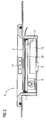
- eine Mensch-Maschine-Schnittstelle,
- FIG 3
- eine Draufsicht einer Mensch-Maschine-Schnittstelle und
- FIG 4
- ein Beispiel für die Anzeige einer Eingabevorrichtung.
- In FIG 1 wird ein System mit einer Projektierungsvorrichtung 3 und einer Mensch-Maschine-Schnittstelle 5 dargestellt. Durch das System 1 werden Eingaben über die Mensch-Maschine-Schnittstelle 5 bereitgestellt. Eine Projektierungsvorrichtung 3, z. B. ein Projektierungsrechner, ist zur Projektierung der Mensch-Maschine-Schnittstelle 5 vorgesehen. Die grafischen Daten 12 und die Funktionsdaten 13 der Mensch-Maschine-Schnittstelle 5 werden in der Projektierungsvorrichtung 3 konfiguriert, d.h. das Layout der Anzeige 16 der Mensch-Maschine-Schnittstelle 5 und die mit dem Layout verknüpften Eingabefunktionen werden projektiert. Bei der Projektierung der Funktionsdaten 13 werden die Koordinaten von Eingabefunktionen und deren Rückmeldungen ebenfalls bereitgestellt. Zudem werden dynamische Informationen, z. B. in Form von Rückmeldungen mittels projizierter Laserstrahlen, projektiert. Anschließend werden die grafischen Daten an einen herkömmlichen Drucker 10 weitergeleitet, wohingegen die Funktionsdaten in der Mensch-Maschine-Schnittstelle 5 oder in einem tragbaren Speicher 14, z.B. einer CD, einer Diskette oder einem USB-Speicher, gespeichert werden. Durch den Drucker 10 wird das Layout auf einem Druckpapier 11 gedruckt, anschließend kann das gedruckte Druckpapier 11 als Anzeige 16 in der Mensch-Maschine-Schnittstelle 5 eingesetzt werden. Die Eingaben, die gemäß dem Layout an der Mensch-Maschine-Schnittstelle 5 ausgeführt werden, sind wie bei konventionellen Mensch-Maschine-Schnittstellen erfassbar. Dadurch wird eine Mensch-Maschine-Schnittstelle 5 bereitgestellt, deren Anzeige 16 flexibel und kostengünstig einsetzbar ist. Eine derartige Mensch-Maschine-Schnittstelle 5 ermöglicht die Verwendung in mehreren Bereichen.
- FIG 2 zeigt eine Mensch-Maschine-Schnittstelle 5, die einen Touchscreen 2 zur Eingabe, eine Anzeigefläche 4 zur Visualisierung der Anzeige 16 des Touchscreens 2 und eine elektronische Einheit 15 zur Speicherung und Auswertung der Funktionsdaten 13 aufweist. Wie bereits erläutert bzw. wie in FIG 3 dargestellt, kann die Anzeigefläche 4 ein Druckpapier 11 oder eine Folie sein, welche leicht ohne Demontierung der Mensch-Maschine-Schnittstelle 5 unter dem Touchscreen 2 eingesetzt bzw. herausgenommen werden kann. Dementsprechend umfasst die Mensch-Maschine-Schnittstelle 5 eine Klammer 7 als Aufnahmevorrichtung und als Dämpfungsmittel, um die Anzeigefläche 4 zu fixieren. Die Anzeigestruktur (Layout) des Touchscreens 2, wie Tasten, Knöpfe, Lampenanordnungen, ist auf der Anzeigefläche 4 gedruckt visualisiert (FIG 3). Die Mensch-Maschine-Schnittstelle 5 umfasst zudem einen Projektionslaser 17, der farbige Laserstrahlen auf der Anzeigefläche 4 projizieren kann. Mittels der Laserstrahlen können dynamische Informationen, z.B. Meldeleuchten, auf der Anzeige 16 des Touchscreen 2 dargestellt werden, um auf eine Rückmeldung bzw. eine Bestätigung von Eingaben hinzuweisen. Darüber hinaus weist die Mensch-Maschine-Schnittstelle 5 eine Vibrations-Technologie auf, um eine haptische Rückmeldung (Feedback) zu stimulieren. Zur Vornahme von haptischen Rückmeldungen wird die Mensch-Maschine-Schnittstelle 5 mit einem Vibrationsmodul 8 und einer Vibrationsplatte 18 ausgerüstet. Das Vibrationsmodul 8 berechnet nach einer Eingabe ein Frequenzsignal, dementsprechend kann eine Vibration über die Vibrationsplatte 18 generiert werden. Die Frequenz des Signals ist einstellbar, wodurch auch ein akustisches Signal erzeugt werden kann. Außerdem umfasst die Mensch-Maschine-Schnittstelle 5 eine Schnittstelle 9 zum Anschluss externer Geräte/Vorrichtungen. Mittels dieser Schnittstelle 9 kann ein externes Gerät, z.B. eine Maus, als Erweiterungseingabevorrichtung an die Mensch-Maschine-Schnittstelle 5 angeschlossen werden.
- Das Layout des Touchscreens 2 wird gemäß FIG 3 auf einem Druckpapier 11 gezeigt, weiterhin wird ein farbiger Laserstrahl von dem Projektionslaser 17 auf das Druckpapier 11 projiziert. Der Laserstrahl dient z. B. als Rückmeldung oder Bestätigungsinfo für eine Eingabe, die über den Touchscreen 2 ausgeführt wurde.
- FIG 4 zeigt ein Beispiel für die Anzeige 22 einer Mensch-Maschine-Schnittstelle mit Touchscreen. Wenn man auf die Taste 19 drückt, wird durch den projizierten Laserstrahl eine Meldeleuchte 20 an dieser Taste 19 und damit eine sichtbare Bestätigung für diese Eingabe erzeugt. Das kann z. B. eine farbige Zustandsanzeige sein. Außerdem kann eine dynamische bzw. blinkende Darstellung (Texte oder Bild) 21 als dynamische Hilfsinformationen auf dem Layout angezeigt werden. Gemäß dem in FIG 4 gezeigten Ausführungsbeispiel weist die Mensch-Maschine-Schnittstelle zudem ein Feedback in Form von Vibration auf. So vibriert die Taste 19 mit jeder Berührung anders. Die Taste 23 vibriert bei Berührung kontinuierlich. Der Slider 24 ist hingegen mit einer Grundvibration versehen, die beim Ziehen verstärkt oder geschwächt wird.
Claims (9)
- System (1) mit einer Projektierungsvorrichtung (3) und einer Mensch-Maschine-Schnittstelle (5) mit einer Eingabevorrichtung (2) und einer Ausgabevorrichtung (6), wobei die Projektierungsvorrichtung (3) zur Projektierung der Mensch-Maschine-Schnittstelle (5) vorgesehen ist, wobei statische Informationen mit einem ersten Mittel (4) visualisierbar sind, wobei dynamische Ausgabeinformationen mit der Ausgabevorrichtung (6) darstellbar sind, wobei Eingaben mit der Eingabevorrichtung (2) erfassbar sind, wobei mit der Projektierungsvorrichtung (3) die Verknüpfung der statischen Informationen, der dynamischen Ausgabeinformationen und der Eingaben derart projektierbar ist, dass als Ergebnis ein auf den statischen Informationen basierendes Layout und Daten zur Konfiguration der Eingabevorrichtung (2) und der Ausgabevorrichtung (6) bereitstellbar sind.
- System (1) nach Anspruch 1,
dadurch gekennzeichnet, dass
die Eingabevorrichtung (2) ein Touchscreen ist. - System (1) nach Anspruch 1 oder 2,
dadurch gekennzeichnet, dass
das Layout als ein Druckbild auf dem ersten Mittel (4) bereitstellbar ist und die Mensch-Maschine-Schnittstelle (5) eine Aufnahmevorrichtung (7) zur Aufnahme des ersten Mittels (4) aufweist. - System (1) nach einem der Ansprüche 1 bis 3,
dadurch gekennzeichnet, dass
die Ausgabevorrichtung (6) ein Projektionslaser ist. - System (1) nach Anspruch 4,
dadurch gekennzeichnet, dass
ein von dem Projektionslaser projizierter Laserstrahl farbig ist. - System (1) nach einem der vorherigen Ansprüche,
dadurch gekennzeichnet, dass
die dynamischen Ausgabeinformationen Rückmeldungen zu den Eingaben sind. - System (1) nach einem der vorherigen Ansprüche,
dadurch gekennzeichnet, dass
die Eingabevorrichtung (2) Mittel (8) zur Erzeugung eines Vibrationssignals aufweist. - System (1) nach Anspruch 7,
dadurch gekennzeichnet, dass
die Stärke und/oder die Frequenz des Vibrationssignals einstellbar ist. - System (1) nach einem der vorherigen Ansprüche,
dadurch gekennzeichnet, dass
die Eingabevorrichtung mindestens eine Schnittstelle (9) zum Anschluss einer externen Vorrichtung umfasst.
Priority Applications (1)
| Application Number | Priority Date | Filing Date | Title |
|---|---|---|---|
| EP05025358A EP1798633A1 (de) | 2005-11-21 | 2005-11-21 | System mit einer Projektierungsvorrichtung und einer Mensch-Maschine-Schnittstelle |
Applications Claiming Priority (1)
| Application Number | Priority Date | Filing Date | Title |
|---|---|---|---|
| EP05025358A EP1798633A1 (de) | 2005-11-21 | 2005-11-21 | System mit einer Projektierungsvorrichtung und einer Mensch-Maschine-Schnittstelle |
Publications (1)
| Publication Number | Publication Date |
|---|---|
| EP1798633A1 true EP1798633A1 (de) | 2007-06-20 |
Family
ID=35708616
Family Applications (1)
| Application Number | Title | Priority Date | Filing Date |
|---|---|---|---|
| EP05025358A Ceased EP1798633A1 (de) | 2005-11-21 | 2005-11-21 | System mit einer Projektierungsvorrichtung und einer Mensch-Maschine-Schnittstelle |
Country Status (1)
| Country | Link |
|---|---|
| EP (1) | EP1798633A1 (de) |
Citations (5)
| Publication number | Priority date | Publication date | Assignee | Title |
|---|---|---|---|---|
| US4977310A (en) * | 1988-02-02 | 1990-12-11 | Lgz Landis & Gyr Zug | Programmable control or regulating device |
| EP0982676A1 (de) * | 1998-08-27 | 2000-03-01 | Hewlett-Packard Company | Verfahren und Vorrichtung für eine virtuelle Anzeige/Tastatur für einen PDA |
| US20020067144A1 (en) * | 2000-05-09 | 2002-06-06 | Hoffknecht Marc O. | Lighting control interface |
| EP1313060A2 (de) * | 2001-11-14 | 2003-05-21 | Nec Corporation | Tragbare Multifunktionsdatenverarbeitungsvorrichtung |
| US20030212896A1 (en) * | 2001-12-20 | 2003-11-13 | Andrew Kisliakov | User interface for accessing files in a smartcard file |
-
2005
- 2005-11-21 EP EP05025358A patent/EP1798633A1/de not_active Ceased
Patent Citations (5)
| Publication number | Priority date | Publication date | Assignee | Title |
|---|---|---|---|---|
| US4977310A (en) * | 1988-02-02 | 1990-12-11 | Lgz Landis & Gyr Zug | Programmable control or regulating device |
| EP0982676A1 (de) * | 1998-08-27 | 2000-03-01 | Hewlett-Packard Company | Verfahren und Vorrichtung für eine virtuelle Anzeige/Tastatur für einen PDA |
| US20020067144A1 (en) * | 2000-05-09 | 2002-06-06 | Hoffknecht Marc O. | Lighting control interface |
| EP1313060A2 (de) * | 2001-11-14 | 2003-05-21 | Nec Corporation | Tragbare Multifunktionsdatenverarbeitungsvorrichtung |
| US20030212896A1 (en) * | 2001-12-20 | 2003-11-13 | Andrew Kisliakov | User interface for accessing files in a smartcard file |
Similar Documents
| Publication | Publication Date | Title |
|---|---|---|
| EP3040816B1 (de) | Verfahren und vorrichtung zur eingabe von daten mit zwei eingabearten und haptischer rückkopplung, insbesondere in einem kraftfahrzeug | |
| EP1319214B1 (de) | Berührungssensitive anzeige mit taktiler rückkopplung | |
| DE10051680B4 (de) | Schema zur Darstellung mehrerer Druckauftragsabänderungselemente in einer Drucksoftware-Benutzerschnittstelle | |
| EP3303043B1 (de) | Bedienvorrichtung mit schneller haptischer rückmeldung | |
| EP2100197A1 (de) | Bedieneinheit mit touchscreen-tasten | |
| DE20101768U1 (de) | Anzeige- und Bedienvorrichtung, insbesondere Touch Panel | |
| DE102013112090A1 (de) | Berührungsempfindlicher Bildschirm für Luftfahrzeuge und Betriebsverfahren für diesen | |
| DE102018102633A1 (de) | Eingabe- und ausgabevorrichtung mit fühlbarer rückmeldung | |
| CH703401B1 (de) | Verfahren und Vorrichtung zum Erzeugen einer Benutzerschnittstelle zum Bedienen von Maschinen. | |
| DE102015209593A1 (de) | Bedienvorrichtung mit schneller haptischer Rückmeldung | |
| DE112011105895T5 (de) | Projektdatenerzeugungsvorrichtung und programmierbare Anzeigevorrichtung | |
| DE102014019599B4 (de) | Elektronische Vorrichtung und Anzeigesteuerungsverfahren derselben | |
| EP2312429A1 (de) | Verfahren zum Bereitstellen einer Benutzerschnittstelle und Bedienvorrichtung | |
| DE102016108899A1 (de) | Kombiniertes Ein- und Ausgabegerät und Verfahren zur Bedienung eines Ein- und Ausgabegerätes | |
| EP0284007B1 (de) | Dateneingabe an Druckmaschinen | |
| DE102016207530A1 (de) | System und Verfahren zum Darstellen eines virtuellen Fahrzeuginnenraums | |
| EP1850305A2 (de) | Anzeigevorrichtung zur taktil erfassbaren Darstellung von Anzeigeelementen sowie Anzeigesystem mit einer solchen Anzeigevorrichtung | |
| DE2260328B2 (de) | Eingabetableau | |
| DE102016014774A1 (de) | Berührungsempfindliche Anzeigeeinrichtung mit haptischer Rückmeldung | |
| EP1361056A1 (de) | Projektion von Informationen von Zusatzsystemen an einem Leitstand | |
| DE4008743A1 (de) | Tastatur-eingabe- und anzeige-einheit mit variablen zeichensaetzen | |
| DE102024125737B3 (de) | System mit einer Recheneinrichtung und einem Lenkrad für ein Kraftfahrzeug | |
| EP1832944A1 (de) | Baugruppe für ein Automatisierungssystem | |
| DE69115316T2 (de) | Eingabeinformationsverarbeitungsgerät mit Zeigereinrichtung | |
| DE60311087T2 (de) | Eine Bediener-Aktivierungsvorrichtung sowie Anordnung hierzu |
Legal Events
| Date | Code | Title | Description |
|---|---|---|---|
| PUAI | Public reference made under article 153(3) epc to a published international application that has entered the european phase |
Free format text: ORIGINAL CODE: 0009012 |
|
| AK | Designated contracting states |
Kind code of ref document: A1 Designated state(s): AT BE BG CH CY CZ DE DK EE ES FI FR GB GR HU IE IS IT LI LT LU LV MC NL PL PT RO SE SI SK TR |
|
| AX | Request for extension of the european patent |
Extension state: AL BA HR MK YU |
|
| 17P | Request for examination filed |
Effective date: 20070621 |
|
| 17Q | First examination report despatched |
Effective date: 20070803 |
|
| AKX | Designation fees paid |
Designated state(s): DE FR GB IT |
|
| STAA | Information on the status of an ep patent application or granted ep patent |
Free format text: STATUS: THE APPLICATION HAS BEEN REFUSED |
|
| 18R | Application refused |
Effective date: 20100822 |