EP1798751A1 - Diaphragme pour la protection d' emetteur de particules chargées - Google Patents
Diaphragme pour la protection d' emetteur de particules chargées Download PDFInfo
- Publication number
- EP1798751A1 EP1798751A1 EP05027205A EP05027205A EP1798751A1 EP 1798751 A1 EP1798751 A1 EP 1798751A1 EP 05027205 A EP05027205 A EP 05027205A EP 05027205 A EP05027205 A EP 05027205A EP 1798751 A1 EP1798751 A1 EP 1798751A1
- Authority
- EP
- European Patent Office
- Prior art keywords
- aperture
- charged particle
- particle beam
- chamber
- pressure
- Prior art date
- Legal status (The legal status is an assumption and is not a legal conclusion. Google has not performed a legal analysis and makes no representation as to the accuracy of the status listed.)
- Withdrawn
Links
- 239000002245 particle Substances 0.000 title claims abstract description 76
- 230000000903 blocking effect Effects 0.000 claims abstract description 25
- 238000000034 method Methods 0.000 claims abstract description 9
- 230000003287 optical effect Effects 0.000 claims description 23
- 238000009792 diffusion process Methods 0.000 claims description 12
- 238000010894 electron beam technology Methods 0.000 description 23
- 238000005086 pumping Methods 0.000 description 6
- 238000007493 shaping process Methods 0.000 description 6
- 230000004075 alteration Effects 0.000 description 5
- 150000002500 ions Chemical class 0.000 description 4
- 238000005452 bending Methods 0.000 description 2
- 230000008901 benefit Effects 0.000 description 2
- 238000011109 contamination Methods 0.000 description 2
- 230000007423 decrease Effects 0.000 description 2
- 238000007689 inspection Methods 0.000 description 2
- 238000004519 manufacturing process Methods 0.000 description 2
- 238000012986 modification Methods 0.000 description 2
- 230000004048 modification Effects 0.000 description 2
- 230000035945 sensitivity Effects 0.000 description 2
- 238000004804 winding Methods 0.000 description 2
- 230000008859 change Effects 0.000 description 1
- 238000004140 cleaning Methods 0.000 description 1
- 230000001419 dependent effect Effects 0.000 description 1
- 238000003795 desorption Methods 0.000 description 1
- 239000006185 dispersion Substances 0.000 description 1
- 238000002389 environmental scanning electron microscopy Methods 0.000 description 1
- 238000003384 imaging method Methods 0.000 description 1
- 238000001459 lithography Methods 0.000 description 1
- 238000004886 process control Methods 0.000 description 1
- 239000004065 semiconductor Substances 0.000 description 1
- 239000000758 substrate Substances 0.000 description 1
Images




Classifications
-
- H—ELECTRICITY
- H01—ELECTRIC ELEMENTS
- H01J—ELECTRIC DISCHARGE TUBES OR DISCHARGE LAMPS
- H01J37/00—Discharge tubes with provision for introducing objects or material to be exposed to the discharge, e.g. for the purpose of examination or processing thereof
- H01J37/30—Electron-beam or ion-beam tubes for localised treatment of objects
- H01J37/301—Arrangements enabling beams to pass between regions of different pressure
-
- H—ELECTRICITY
- H01—ELECTRIC ELEMENTS
- H01J—ELECTRIC DISCHARGE TUBES OR DISCHARGE LAMPS
- H01J37/00—Discharge tubes with provision for introducing objects or material to be exposed to the discharge, e.g. for the purpose of examination or processing thereof
- H01J37/02—Details
- H01J37/18—Vacuum locks ; Means for obtaining or maintaining the desired pressure within the vessel
-
- H—ELECTRICITY
- H01—ELECTRIC ELEMENTS
- H01J—ELECTRIC DISCHARGE TUBES OR DISCHARGE LAMPS
- H01J2237/00—Discharge tubes exposing object to beam, e.g. for analysis treatment, etching, imaging
- H01J2237/18—Vacuum control means
- H01J2237/188—Differential pressure
Definitions
- the present invention generally relates to a charged particle apparatus and more particularly to a charged particle apparatus and a method with protection arrangements for an emitter located in vacuum. More specifically, the present invention relates to a charged particle beam apparatus and a method of protecting an emitter tip with an aperture.
- Charged particle beam apparatuses are used in a plurality of industrial fields, including, but not limited to, high resolution imaging and processing of samples, inspection of semiconductor devices during manufacturing, exposure systems for lithography, detecting devices and testing systems.
- Micrometer and nanometer scale process control, inspection, or structuring is often done with charged particle beams, e.g. electron beams.
- Charged particle beams offer superior spatial resolution compared to, e.g. photon beams due to their short wavelengths.
- the throughput is an issue of such devices. Since large substrate areas have to be patterned or inspected, it is desirable that the throughput is, for example larger than 10 cm 2 /min. In charged particle beam devices, the throughput depends on the charged particle beam current. Thus, there is a need for increasing the beam current.
- high current charged particle beam emitters such as field emission emitters have an enormous potential due to their high brightness. Yet, these and other emitters have an increased sensitivity for particles being adsorbed by the emitter. Residual gas molecules being adsorbed on the emitting surface of the emitter may cause poor stability of the emitter.
- each chamber usually has its own vacuum level.
- the chambers may be separated with differential pressure apertures.
- the gun chamber that is the chamber in which the emitter is located, needs to be cleaned in special cleaning steps to achieve the required vacuum conditions in the gun chamber.
- the most critical parts are those which are illuminated by the charged particle beam, e.g. the extractor electrode.
- the gun chamber may be cleaned with electron bombardment.
- vacuum levels in the gun chamber of 10 -12 torr (1.333*10 -12 mbar) or better can be realized. This results in a very small amount of molecules from the gun chamber that may be adsorbed by the emitter.
- the flow of gas from higher pressure chambers may not be sufficient to change the pressure in higher vacuum chambers significantly.
- the differential pressure aperture for separating the gun chamber from the other chamber or other chambers is located directly below the emitter.
- the probability of molecules originating from the specimen chamber being adsorbed on the surface of the emitter is about in the same range as for the molecules originating from the gun chamber itself.
- the charged particle beam apparatus includes: a charged particle emitter located within a gun chamber, the gun chamber being adapted to encompass a first pressure; at least one further vacuum chamber adapted to encompass a second pressure between one order and four orders of magnitude higher than the first pressure; a first aperture unit including a molecule blocking area and at least one first aperture opening; a second aperture unit including a second aperture opening, wherein the first aperture unit and/or the second aperture unit is a differential pressure aperture separating two independently evacuateable vacuum chambers and being adapted for maintaining a pressure difference of at least two orders of magnitude, and wherein the emitter, the molecule blocking area and the second aperture opening are positioned to be on a straight line.
- the at least one first aperture opening, the second aperture opening and the emitter are not located on a straight line or prevent direct sight from the position of the emitter to the specimen chamber.
- the molecule blocking area is typically a central molecule blocking area. That is, it is located substantially in the center of the aperture unit or substantially on the optical axis of the charged particle beam apparatus.
- differential pressure apertures eliminates direct sight of the specimen chamber (wafer chamber) to the charged particle beam emitter. Thereby, the probability of molecules having their origin outside the gun chamber, e.g. in the specimen chamber, being adsorbed on the emitter surface is reduced. As a result, the sensitivity of the emitter to the conditions outside the gun chamber, that is e.g. in the specimen chamber, is reduced.
- a charged particle beam apparatus wherein the second aperture unit is a differential pressure aperture separating the gun chamber from the further vacuum chamber and being adapted for maintaining a pressure difference of at least two orders of magnitude.
- a charged particle beam apparatus wherein a specimen chamber being adapted to encompass a third pressure between one order and four orders of magnitude higher than the second pressure is included and wherein the second aperture unit is a differential pressure aperture separating the specimen chamber from the further vacuum chamber and being adapted for holding a pressure difference of at least two orders of magnitude.
- a charged particle beam apparatus including: a charged particle emitter located within a gun chamber, the gun chamber having a first pressure; the charged particle beam emitter including an emitter tip adapted for emission of a charged particle beam; a first differential pressure aperture including at least one first aperture opening, a second differential pressure aperture including a second aperture opening, the second differential pressure aperture separating the gun chamber from a further chamber or a further chamber from a specimen chamber, the gun chamber being adapted for a pressure at least a factor of 100 lower than the further chamber or the specimen chamber; wherein the emitter tip, each one of all of the aperture openings of the first aperture unit, and the second aperture opening are positioned to be not in a straight line.
- a charged particle beam apparatus includes a charged particle emitter located within a gun chamber, the gun chamber having a first pressure; the charged particle beam emitter includes an emitter tip adapted for emission of a charged particle beam, a first differential pressure aperture unit including at least one first aperture opening, a second differential pressure aperture unit including a second aperture opening, the second differential pressure aperture separating the gun chamber from a second chamber or a second chamber from a specimen chamber, a beam bending unit for providing a non-straight vision charged particle beam path adapted for preventing direct vision (a straight diffusion path) from the emitter through all of the first aperture openings and through the second aperture opening.
- a charged particle beam apparatus includes: a charged particle beam emitter located within a gun chamber, the gun chamber having a first pressure; the charged particle beam emitter includes an emitter tip adapted for emission of a charged particle beam for impingement on a plurality of impingement locations; a first aperture unit including a first beam blocking area, a second differential pressure aperture unit including a second aperture opening, the second differential pressure aperture separating the gun chamber from a further chamber or a further chamber from a specimen chamber and being adapted for maintaining a pressure difference between the respective two chambers of at least two orders of magnitude.
- the emitter tip, the beam blocking area and each one of the plurality of impingement locations are positioned to prevent a diffusion path from the impingement locations to the emitter.
- Embodiments are also directed to apparatuses for carrying out the disclosed methods and including apparatus parts for performing each described method step. These method steps may be performed by way of hardware components, a computer programmed with appropriate software, or by any combination of the above two or in any other manner. Furthermore, embodiments are also directed to methods by which the described apparatus operates. It includes method steps for carrying out every function of the apparatus or manufacturing every part of the apparatus.
- the following embodiments will be described with reference to electron beams and field emitters, specifically cold field emitters. This is not to be understood as a limitation to the invention.
- the invention can also be applied to other charged particles and other types of emitters which require protection from molecules that may adsorb undesirably at the surface thereof.
- the present invention may also be used for ions and respective ion emitters.
- Fig. 1 shows a first embodiment of a charged particle beam apparatus 100.
- An emitting unit which comprises an emitter 1 and an extractor 14, emits electron beam 110.
- the electron beam is to be focused by an objective lens 6 on specimen 4, which is located on a specimen stage (not shown). Without deflection means 22, 24, 25, 26, the beam would travel substantially along optical axis 2.
- the primary electron beam 110 causes secondary and backscattered particles to be released by specimen 4.
- the emitting unit is located in gun chamber 11. Electron beam 110 is guided from gun chamber 11 to intermediate vacuum chamber 12 into specimen chamber 13. Each of the chambers has a pumping port 3, 5, and 7, respectively. The three vacuum chambers are separated from each other by differential pressure aperture units 102, 104.
- differential pressure apertures can have two different forms. On the one hand, they can be formed by a tube. This form may be used if the diameter of the differential pressure aperture, that is the opening of the differential pressure aperture unit, can not be reduced sufficiently. If the size of the opening needs to be in the range of about 1 mm because of the diameter of the primary electron beam, because of a required deflection of the primary electron beam, because of simplicity of alignment, or because of other reasons, the length of the differential pressure opening needs to be increased in order to increase the resistance for air flowing through the aperture. This form then has typically a diameter of the opening between about 1 mm and about 2 mm and a length of the tube that is about 5 times to about 20 times the diameter. Such a tube differential pressure aperture typically allows for a pressure difference between two orders of magnitude to three orders of magnitude.
- the second form for a differential pressure aperture can be a disc with a small opening.
- Typical thickness of the disc may be in the range of about 100 ⁇ m to about 500 ⁇ m.
- Typical diameters of the aperture opening may be in the range of about 20 ⁇ m to about 200 ⁇ m.
- Differential pressure apertures are used as aperture units separating independently evacuateable vacuum chambers and are adapted to hold/maintain a defined pressure difference. This may for example be two to four orders of magnitude.
- the embodiment of fig. 1 shows three chambers 11, 12, and 13. Each chamber has a different pressure.
- the pressure in the specimen chamber is about 1*10 -6 torr or less (1.333*10 -6 mbar or less).
- Specimen chamber 13 is pumped with a turbo pump having a pumping speed of for example 300 1/s.
- the first differential pressure aperture has the form of a tube with the diameter of about 1.5 mm and a length of about 15 mm.
- the pressure in the intermediate vacuum chamber 12 is about 1*10 -7 torr or less (1.333*10 -7 mbar or less). This chamber is pumped by a 20-60 l/s ion getter pump.
- Intermediate vacuum chamber 12 and gun chamber 11 are separated from each other by a differential pressure aperture provided by a multi-aperture with holes arranged on a circle.
- the diameter of the openings of the aperture unit are about 1 mm. This aperture unit is used at the same time as a selectable final aperture for the electron beam.
- an aperture opening with a thickness of about 100 ⁇ m and a diameter of about 100 ⁇ m and may then hold ca. for orders of magnitude in pressure difference.
- the final aperture is defined as the last beam shaping aperture. That is, the final aperture blocks a part of the beam to shape the beam. And the final aperture is the last beam shaping aperture before the primary charged particle beam impinges on specimen 4.
- Differential pressure aperture unit 102 separates the intermediate vacuum chamber 12 from the gun chamber 11.
- the upper vacuum chamber that is the gun chamber, is pumped with an ion getter pump with a pumping speed of about 20-60 l/s.
- the pressure in the gun chamber is about 1*10 -10 torr or less (1.333*10 -10 mbar or less).
- the aperture openings of differential pressure aperture unit 102 are off-axis.
- the openings of the aperture unit are not located on optical axis 2.
- Aperture unit 102 has a molecule blocking area at the position of the optical axis 2.
- the differential pressure aperture unit 104 has its opening on the optical axis 2.
- a deflection system is provided in order to guide the primary electron beam through the electron beam column.
- Fig. 1 shows a 4-B-deflection system.
- four magnetic deflectors 22, 24, 25, and 26 are used.
- First deflector 22 deflects the beam away from the optical axis 2
- the second deflector 24 redirects the primary electron beam to travel substantially parallel to optical axis 2.
- the beam travels off-axis.
- primary electron beam 110 is deflected towards optical axis 2 by deflector 25.
- the fourth deflector 26 redirects the primary electron beam to travel substantially along optical axis 2.
- the embodiment of fig. 1 provides a first aperture unit with the first opening, a second aperture unit with at least one second opening and an emitter.
- the first opening, the second openings and the emitter are not located on one straight line. That is, a molecule blocking area of the aperture unit, the opening of another aperture unit, and the emitter are located on a straight-line. Therefore, molecules defusing from specimen chamber 13 into the intermediate vacuum chamber 12 can not reach the emitter.
- an electron beam 110 emitted by emitter 1 is directed on specimen 4.
- the electron beam travels through aperture 204, aperture 202 and through component 214.
- component 114 is an extractor.
- component 214 may be a further aperture, particularly a differential pressure aperture, separating the gun chamber from a neighboring chamber.
- Deflection system including deflectors 222, 224, 225, and 226 guides the electron beam 110 through the various openings in the system.
- Deflectors 222, 224, 225, and 226 form a 4-stage deflection system.
- the deflectors may be electrostatic, magnetic or combined magnetic-electrostatic.
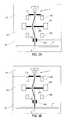
- Figs. 2A and 2B provide schematic drawings indicating different chambers 11, 12 and 13 of the charged particle column.
- aperture unit 204 which may typically be a differential pressure aperture unit, separates the specimen chamber 13 from a neighboring chamber 12.
- the specimen chamber includes an objective lens (not shown in fig. 2), a specimen stage for retaining the specimen and a pumping port.
- Deflectors 225 and 226 are located in an intermediate vacuum chamber 12, which is separated from the gun chamber 111 by aperture unit 202. Within the gun chamber deflectors 222 and 224 and extractor 114 are provided.
- all four deflectors may be provided within one or more intermediate vacuum chambers.
- Component 214 is a differential pressure aperture unit.
- Emitter 1 is located in the gun chamber separated from a neighboring intermediate vacuum chamber by aperture unit 214.
- the emitter may be provided with additional extractors or anodes.
- Figs. 2A and 2B show aperture units 202, which may be a differential pressure aperture unit, with one opening. Nevertheless, according to a typical arrangement, the opening in the aperture unit 202 may form the final aperture of the charged particle beam column.
- Aperture unit 202 has one opening, which is located off-axis. Further, there is the beam blocking area of aperture unit 202, which is located on-axis. Thus, a straight diffusion path for molecules defusing from a lower part of the system, particularly the specimen chamber, is prevented. Thus, the probability of molecules originating from a low part of the system to be adsorbed on the surface of the emitter is reduced.
- aperture units which may typically be differential pressure aperture units, the emitter, the specimen, and the above described different possible arrangements of chambers may be provided similarly to the embodiments described with respect to figs. 2A and 2B.
- the deflection systems shown in figs. 3A and 3B are a 3-stage deflection system including deflectors 322, 324 and 326.
- the deflectors may be electrostatic, magnetic or combined magnetic-electrostatic.
- the deflection system may be provided such that after all three or four deflections, respectively, the charged particle beam travels along the same axis as before any of the deflections.
- this axis will be the optical axis.
- the electron beam is emitted from the emitter along the optical axis and the last deflector redirects the beam to travel again substantially along the optical axis. Thereby, aberrations introduced by the deflection system are minimized.
- this may be realized by a symmetric arrangement of the deflectors.
- the same absolute values of currents may be applied to all four deflectors.
- the same absolute values of potentials may be applied to all deflectors.
- Corresponding relationships also apply for combined magnetic-electrostatic deflectors.
- the relation between the absolute values of the deflection angles can preferably be realized by connecting the deflection stages in one electrical circuit.
- the deflection angles may be similar for the first and third deflection stage and, for the second deflection stage, a multiple thereof. If this symmetry is further combined with an arrangement of the deflection stages with respect to each other such that the distance between the first and the second deflection stage is similar to the distance between the second and the third deflection stage, aberrations and dispersion can be minimized.
- the relation between the absolute values of the deflection angles can preferably be realized by connecting the deflection stages in one electrical circuit.
- the number of windings of deflected 324 may be twice as large as the number of findings in deflectors 322 and 326. In fig. 3, this is indicated by the increased size of deflector 324.
- deflection is realized by connecting the deflection stages in one electrical circuit, variations of the applied current or voltage concern the deflection stages equally.
- the different deflection directions can be realized by the direction of the windings or the direction of the current applied.
- the deflection is conducted in a symmetrical manner.
- aberrations can be minimized.
- embodiments having different deflection angles for all three deflectors can also be realized.
- aberrations are minimized as long as the charged particle beam travels substantially along the same axis after deflection of the deflection system as compared to before deflection of the deflection system.
- the same above-mentioned arguments apply for the usage of four deflectors.
- solely the absolute values of the deflection angles of the first and second deflectors and the absolute values of the deflection angles of the third and fourth deflectors have to be equal in the event the distance from the first deflectors to the second deflector is the same as the distance from the third deflector to the fourth deflector.
- the charged particle beam can travel substantially parallel to the optical axis through aperture unit 202. That is, the charged particle beam travels substantially perpendicular to the aperture unit through the aperture unit opening.
- this advantage coincides with the disadvantage of increased space requirement and/or column length.
- Figs. 4A and 4B show a 4-stage deflection system including deflectors 222, 224, 225 and 226.
- the aperture units 402 include a plurality of aperture openings. Thereby, particularly in the event of the aperture unit 402 forming the final aperture, a plurality of aperture openings can be used as desired.
- the beam shaping capability of one aperture opening may decrease because of contamination of the aperture opening. Contamination may for example occur since the aperture opening of a final aperture blocks a part of the electron beam. As a result, the area around the aperture opening may get charged. This may again result in attraction of particles which are then located in the area of the aperture opening that is formed to shape the beam. Particles located in the aperture opening can thus deteriorate the beam shaping quality of the final aperture. If the beam shaping quality decreases, another aperture opening of the plurality of openings of the aperture unit 402 may instead be used.
- the aperture openings of the aperture unit 402 acting as a final aperture may have different diameters. Thereby, different electron beam diameters and, thus, different beam currents may be generated by switching from one aperture opening to another aperture opening.
- Figs. 4A and 4B provide schematic drawings indicating different chambers of the charged particle column.
- aperture unit 204 which may typically be a differential pressure aperture unit, separates the specimen chamber from a neighboring chamber.
- the specimen chamber 13 includes an objective lens (not shown in fig. 4), a specimen stage for retaining the specimen and a pumping port.
- Deflectors 225 and 226 are located in an intermediate vacuum chamber 12, which is separated from the gun chamber by aperture unit 202. Within the gun chamber deflectors 222 and 224 and extractor 114 are provided.
- all four deflectors may be provided within one or more intermediate vacuum chambers.
- Component 214 is a differential pressure aperture unit.
- Emitter 1 is located in the gun chamber separated from a neighboring intermediate vacuum chamber by aperture unit 214.
- the emitter may be provided with additional extractors or anodes.
- Fig. 6A shows a charged particle beam system with emitter 1. Electron beam 610 travels through openings of aperture units 602 and 204. Again, the openings of aperture units 602 and 202 are not located on a straight-line with emitter 1. One of the aperture units has a molecule blocking area, which is located on a straight-line with the emitter and the opening of the other aperture unit. Thereby, a straight molecule diffusion path is prevented.
- the optical axis of the electron beam system is bent by deflector 624.
- the electron beam system is a non-straight vision system. This arrangement also eliminates the direct visibility (straight-line) from the wafer to the tip of the emitter. As a result, the diffusion of molecules from a lower part of the electron system, particularly the specimen chamber, is reduced.
- the bending of the optical axis in figs. 6A and 6B is provided by the magnetic deflector.
- the optical axis may also be bent by a sector field.
- aperture unit 204 which may typically be a differential pressure aperture unit, separates a specimen chamber 13 from a neighboring chamber.
- the specimen chamber includes an objective lens (not shown in fig. 6), a specimen stage for retaining the specimen and a pumping port.
- Aperture unit 204 separates the specimen chamber from a further chamber, an intermediate vacuum chamber 12.
- aperture 602 may separate the intermediate vacuum chamber from the gun chamber 11.
- Within the gun chamber extractor 114 is provided.
- deflector 624 and aperture 602 may be provided within one or more intermediate vacuum chambers.
- Component 214 may illustrate then a differential pressure aperture unit.
- Emitter 1 is located in the gun chamber separated from a neighboring intermediate vacuum chamber by aperture unit 214.
- the emitter may be provided with additional extractors or anodes.
- any one of the aperture units may be used as aperture units not separating independently evacuateable vacuum chambers. In this case, one of the aperture units may be located within one pressure stage.
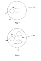
- FIG. 7 shows aperture unit 702 having a disk element 703 including molecule blocking area 706. Area 706 is indicated by dashed lines.
- Aperture unit 702 further includes aperture opening 704, which is provided outside the center axis of the aperture unit. In the event aperture unit 702 is provided as a differential pressure aperture unit, opening 704 may be formed of an elongated tube to increase the pressure resistance of the differential pressure aperture unit, as generally described above.
- FIG. 8 shows an aperture unit 802.
- Aperture unit 802 includes disk element 803 with molecule blocking area 806.
- Molecule blocking area 806 is indicated with dashed lines in fig. 8. Contrary to the embodiment explained with respect to fig. 7, fig. 8 includes a plurality of aperture openings 804a, 804b, and 804c.
- aperture openings 804 may have the same diameter. Thereby, redundancy of aperture openings may be provided.
- aperture openings 804 may have differently sized openings. Thereby, one of the differently sized openings may be chosen according to the desired application. Further, it is possible that some of the aperture openings 804 have the same diameter to provide redundancy and some of the openings have different diameters to be able to adapt the charged particle beam diameter to the desired application.
- openings 804 may be formed of an elongated tube to increase the pressure resistance of the differential pressure aperture unit, as generally described above.
- the aperture openings 804 are positioned off-axis so that a direct sight from the wafer to the emitter is prevented. If the aperture openings are at the same time used to form the final apertures, multiple apertures may typically be provided. The openings may then be arranged on a circle concentric to the optical axis.
- the embodiment shown in fig. 1 has three aperture openings. However, according to different embodiments, also two, four, five, six or even a higher number of aperture openings may be provided in the aperture unit 802.
- the at least three openings may typically be positioned on a concentric circle around the optical axis or the molecule blocking area.
Landscapes
- Chemical & Material Sciences (AREA)
- Analytical Chemistry (AREA)
- Electron Beam Exposure (AREA)
Priority Applications (2)
| Application Number | Priority Date | Filing Date | Title |
|---|---|---|---|
| EP05027205A EP1798751A1 (fr) | 2005-12-13 | 2005-12-13 | Diaphragme pour la protection d' emetteur de particules chargées |
| US11/553,153 US20070145303A1 (en) | 2005-12-13 | 2006-10-26 | Protecting Aperture for Charged Particle Emitter |
Applications Claiming Priority (1)
| Application Number | Priority Date | Filing Date | Title |
|---|---|---|---|
| EP05027205A EP1798751A1 (fr) | 2005-12-13 | 2005-12-13 | Diaphragme pour la protection d' emetteur de particules chargées |
Publications (1)
| Publication Number | Publication Date |
|---|---|
| EP1798751A1 true EP1798751A1 (fr) | 2007-06-20 |
Family
ID=36591333
Family Applications (1)
| Application Number | Title | Priority Date | Filing Date |
|---|---|---|---|
| EP05027205A Withdrawn EP1798751A1 (fr) | 2005-12-13 | 2005-12-13 | Diaphragme pour la protection d' emetteur de particules chargées |
Country Status (2)
| Country | Link |
|---|---|
| US (1) | US20070145303A1 (fr) |
| EP (1) | EP1798751A1 (fr) |
Cited By (2)
| Publication number | Priority date | Publication date | Assignee | Title |
|---|---|---|---|---|
| WO2013013584A1 (fr) * | 2011-07-26 | 2013-01-31 | 中国科学院物理研究所 | Système nanographique et de mesure de caractéristiques électromagnétiques à bande ultra large |
| EP2711967A1 (fr) * | 2012-09-21 | 2014-03-26 | JEOL Ltd. | Microscope électronique à balayage |
Families Citing this family (6)
| Publication number | Priority date | Publication date | Assignee | Title |
|---|---|---|---|---|
| CN102422380A (zh) * | 2009-02-22 | 2012-04-18 | 迈普尔平版印刷Ip有限公司 | 带电粒子微影设备及真空腔室中产生真空的方法 |
| JP2011014244A (ja) * | 2009-06-30 | 2011-01-20 | Hitachi High-Technologies Corp | 荷電粒子銃及び荷電粒子線装置 |
| WO2013012616A2 (fr) | 2011-07-15 | 2013-01-24 | Orbotech Ltd. | Inspection électrique de dispositifs électroniques à l'aide de sondes à plasma induit par faisceau d'électrons |
| CN103365101B (zh) * | 2012-04-01 | 2015-04-08 | 中国科学院物理研究所 | 一种纳米图形化系统及其磁场施加装置 |
| WO2015051175A2 (fr) * | 2013-10-03 | 2015-04-09 | Orbotech Ltd. | Application de sondes à plasma induit par faisceau électronique pour inspection, essai, débogage et modifications de surface |
| WO2025046802A1 (fr) * | 2023-08-30 | 2025-03-06 | 株式会社日立ハイテク | Dispositif à faisceau de particules chargées et son procédé de réglage |
Citations (5)
| Publication number | Priority date | Publication date | Assignee | Title |
|---|---|---|---|---|
| JPS6117386A (ja) * | 1984-07-03 | 1986-01-25 | Mitsubishi Electric Corp | 電子ビ−ム溶接機 |
| WO1988002180A1 (fr) * | 1986-09-18 | 1988-03-24 | Crewe Albert V | Systeme de faisceaux electroniques a pression differentielle, procede et canon |
| EP0999573A1 (fr) | 1998-11-06 | 2000-05-10 | ICT Integrated Circuit Testing Gesellschaft für Halbleiterprüftechnik mbH | Colonne de faisceau de particules chargées |
| US20040076529A1 (en) * | 2000-07-07 | 2004-04-22 | Peter Gnauck | Particle beam device with a particle source to be operated in high vacuum and cascade-type pump arrangement for such a particle beam device |
| EP1515359A1 (fr) | 2003-09-12 | 2005-03-16 | ICT Integrated Circuit Testing Gesellschaft für Halbleiterprüftechnik mbH | Chambre à peu de désorption stimulée par des électrons |
Family Cites Families (10)
| Publication number | Priority date | Publication date | Assignee | Title |
|---|---|---|---|---|
| US4720633A (en) * | 1986-01-17 | 1988-01-19 | Electro-Scan Corporation | Scanning electron microscope for visualization of wet samples |
| US4823006A (en) * | 1987-05-21 | 1989-04-18 | Electroscan Corporation | Integrated electron optical/differential pumping/imaging signal detection system for an environmental scanning electron microscope |
| US5008549A (en) * | 1990-04-10 | 1991-04-16 | Orchid One Corporation | High performance, vacuum compatible electromagnetic lens coil |
| US5254856A (en) * | 1990-06-20 | 1993-10-19 | Hitachi, Ltd. | Charged particle beam apparatus having particular electrostatic objective lens and vacuum pump systems |
| JPH1064467A (ja) * | 1996-08-23 | 1998-03-06 | Toshiba Corp | 電子顕微鏡 |
| WO2001060456A1 (fr) * | 2000-02-19 | 2001-08-23 | Ion Diagnostics, Inc. | Systeme d'inspection a faisceaux d'electrons a plusieurs colonnes et faisceaux |
| JP3728217B2 (ja) * | 2000-04-27 | 2005-12-21 | キヤノン株式会社 | 荷電粒子線露光装置およびデバイス製造方法 |
| EP1760761B1 (fr) * | 2005-09-05 | 2017-10-18 | ICT, Integrated Circuit Testing Gesellschaft für Halbleiterprüftechnik mbH | Emetteur de faisceau à particules chargées et procédé de fonctionnement d'un émetteur de faisceau à particules chargées |
| EP1801838B1 (fr) * | 2005-12-20 | 2012-05-09 | ICT Integrated Circuit Testing Gesellschaft für Halbleiterprüftechnik mbH | Dispositif pour l'émission de particules chargées et procédé pour son opération |
| JP4994151B2 (ja) * | 2007-08-14 | 2012-08-08 | 日本電子株式会社 | 荷電粒子線装置 |
-
2005
- 2005-12-13 EP EP05027205A patent/EP1798751A1/fr not_active Withdrawn
-
2006
- 2006-10-26 US US11/553,153 patent/US20070145303A1/en not_active Abandoned
Patent Citations (5)
| Publication number | Priority date | Publication date | Assignee | Title |
|---|---|---|---|---|
| JPS6117386A (ja) * | 1984-07-03 | 1986-01-25 | Mitsubishi Electric Corp | 電子ビ−ム溶接機 |
| WO1988002180A1 (fr) * | 1986-09-18 | 1988-03-24 | Crewe Albert V | Systeme de faisceaux electroniques a pression differentielle, procede et canon |
| EP0999573A1 (fr) | 1998-11-06 | 2000-05-10 | ICT Integrated Circuit Testing Gesellschaft für Halbleiterprüftechnik mbH | Colonne de faisceau de particules chargées |
| US20040076529A1 (en) * | 2000-07-07 | 2004-04-22 | Peter Gnauck | Particle beam device with a particle source to be operated in high vacuum and cascade-type pump arrangement for such a particle beam device |
| EP1515359A1 (fr) | 2003-09-12 | 2005-03-16 | ICT Integrated Circuit Testing Gesellschaft für Halbleiterprüftechnik mbH | Chambre à peu de désorption stimulée par des électrons |
Non-Patent Citations (1)
| Title |
|---|
| PATENT ABSTRACTS OF JAPAN vol. 010, no. 167 (M - 488) 13 June 1986 (1986-06-13) * |
Cited By (2)
| Publication number | Priority date | Publication date | Assignee | Title |
|---|---|---|---|---|
| WO2013013584A1 (fr) * | 2011-07-26 | 2013-01-31 | 中国科学院物理研究所 | Système nanographique et de mesure de caractéristiques électromagnétiques à bande ultra large |
| EP2711967A1 (fr) * | 2012-09-21 | 2014-03-26 | JEOL Ltd. | Microscope électronique à balayage |
Also Published As
| Publication number | Publication date |
|---|---|
| US20070145303A1 (en) | 2007-06-28 |
Similar Documents
| Publication | Publication Date | Title |
|---|---|---|
| US8957390B2 (en) | Electron gun arrangement | |
| US6797953B2 (en) | Electron beam system using multiple electron beams | |
| JP6220423B2 (ja) | 検査装置 | |
| US7629578B2 (en) | Charged particle beam device | |
| US20070145303A1 (en) | Protecting Aperture for Charged Particle Emitter | |
| TWI773081B (zh) | 用於操作帶電粒子槍的方法、帶電粒子槍,及帶電粒子束裝置 | |
| US7355186B2 (en) | Charged particle beam device with cleaning unit and method of operation thereof | |
| JP4406429B2 (ja) | 電子刺激脱離が少ないチャンバ | |
| JP7789927B2 (ja) | 電子顕微鏡、電子顕微鏡用の電子源、および電子顕微鏡を動作させる方法 | |
| KR102646592B1 (ko) | 하전 입자 빔 장치, 주사 전자 현미경, 및 하전 입자 빔 장치를 작동시키는 방법 | |
| KR102963760B1 (ko) | 전자 현미경, 전자 현미경을 위한 전자 공급원, 및 전자 현미경을 작동시키는 방법들 | |
| US20250285828A1 (en) | Charged particle optical device, assessment apparatus, method of assessing a sample | |
| US8987692B2 (en) | High brightness electron gun, system using the same, and method of operating thereof |
Legal Events
| Date | Code | Title | Description |
|---|---|---|---|
| PUAI | Public reference made under article 153(3) epc to a published international application that has entered the european phase |
Free format text: ORIGINAL CODE: 0009012 |
|
| AK | Designated contracting states |
Kind code of ref document: A1 Designated state(s): AT BE BG CH CY CZ DE DK EE ES FI FR GB GR HU IE IS IT LI LT LU LV MC NL PL PT RO SE SI SK TR |
|
| AX | Request for extension of the european patent |
Extension state: AL BA HR MK YU |
|
| 17P | Request for examination filed |
Effective date: 20071213 |
|
| AKX | Designation fees paid |
Designated state(s): DE GB NL |
|
| 17Q | First examination report despatched |
Effective date: 20091223 |
|
| STAA | Information on the status of an ep patent application or granted ep patent |
Free format text: STATUS: THE APPLICATION IS DEEMED TO BE WITHDRAWN |
|
| 18D | Application deemed to be withdrawn |
Effective date: 20120703 |