EP1799545B1 - Aeronef apte a etre lance en vol et son procede d'utilisation - Google Patents
Aeronef apte a etre lance en vol et son procede d'utilisation Download PDFInfo
- Publication number
- EP1799545B1 EP1799545B1 EP05789189A EP05789189A EP1799545B1 EP 1799545 B1 EP1799545 B1 EP 1799545B1 EP 05789189 A EP05789189 A EP 05789189A EP 05789189 A EP05789189 A EP 05789189A EP 1799545 B1 EP1799545 B1 EP 1799545B1
- Authority
- EP
- European Patent Office
- Prior art keywords
- aircraft
- fuselage
- wings
- elevons
- coupled
- Prior art date
- Legal status (The legal status is an assumption and is not a legal conclusion. Google has not performed a legal analysis and makes no representation as to the accuracy of the status listed.)
- Revoked
Links
- 238000000034 method Methods 0.000 title claims description 7
- 230000008878 coupling Effects 0.000 claims description 4
- 238000010168 coupling process Methods 0.000 claims description 4
- 238000005859 coupling reaction Methods 0.000 claims description 4
- 230000007704 transition Effects 0.000 claims description 2
- 238000004891 communication Methods 0.000 description 9
- 230000007246 mechanism Effects 0.000 description 8
- 238000007906 compression Methods 0.000 description 4
- 230000006835 compression Effects 0.000 description 3
- 230000005484 gravity Effects 0.000 description 3
- 238000009987 spinning Methods 0.000 description 2
- 230000004075 alteration Effects 0.000 description 1
- 230000000712 assembly Effects 0.000 description 1
- 238000000429 assembly Methods 0.000 description 1
- 238000013480 data collection Methods 0.000 description 1
- 238000013500 data storage Methods 0.000 description 1
- 238000010586 diagram Methods 0.000 description 1
- 239000006185 dispersion Substances 0.000 description 1
- 230000008030 elimination Effects 0.000 description 1
- 238000003379 elimination reaction Methods 0.000 description 1
- 229910052987 metal hydride Inorganic materials 0.000 description 1
- 239000000203 mixture Substances 0.000 description 1
- 238000012986 modification Methods 0.000 description 1
- 230000004048 modification Effects 0.000 description 1
- 229910052759 nickel Inorganic materials 0.000 description 1
- PXHVJJICTQNCMI-UHFFFAOYSA-N nickel Substances [Ni] PXHVJJICTQNCMI-UHFFFAOYSA-N 0.000 description 1
- -1 nickel metal hydride Chemical class 0.000 description 1
- 230000008569 process Effects 0.000 description 1
- 230000002250 progressing effect Effects 0.000 description 1
Images



Classifications
-
- B—PERFORMING OPERATIONS; TRANSPORTING
- B64—AIRCRAFT; AVIATION; COSMONAUTICS
- B64U—UNMANNED AERIAL VEHICLES [UAV]; EQUIPMENT THEREFOR
- B64U30/00—Means for producing lift; Empennages; Arrangements thereof
- B64U30/10—Wings
- B64U30/12—Variable or detachable wings, e.g. wings with adjustable sweep
-
- B—PERFORMING OPERATIONS; TRANSPORTING
- B64—AIRCRAFT; AVIATION; COSMONAUTICS
- B64U—UNMANNED AERIAL VEHICLES [UAV]; EQUIPMENT THEREFOR
- B64U70/00—Launching, take-off or landing arrangements
- B64U70/20—Launching, take-off or landing arrangements for releasing or capturing UAVs in flight by another aircraft
-
- B—PERFORMING OPERATIONS; TRANSPORTING
- B64—AIRCRAFT; AVIATION; COSMONAUTICS
- B64U—UNMANNED AERIAL VEHICLES [UAV]; EQUIPMENT THEREFOR
- B64U10/00—Type of UAV
- B64U10/25—Fixed-wing aircraft
-
- B—PERFORMING OPERATIONS; TRANSPORTING
- B64—AIRCRAFT; AVIATION; COSMONAUTICS
- B64U—UNMANNED AERIAL VEHICLES [UAV]; EQUIPMENT THEREFOR
- B64U2101/00—UAVs specially adapted for particular uses or applications
- B64U2101/30—UAVs specially adapted for particular uses or applications for imaging, photography or videography
- B64U2101/31—UAVs specially adapted for particular uses or applications for imaging, photography or videography for surveillance
-
- B—PERFORMING OPERATIONS; TRANSPORTING
- B64—AIRCRAFT; AVIATION; COSMONAUTICS
- B64U—UNMANNED AERIAL VEHICLES [UAV]; EQUIPMENT THEREFOR
- B64U2201/00—UAVs characterised by their flight controls
- B64U2201/10—UAVs characterised by their flight controls autonomous, i.e. by navigating independently from ground or air stations, e.g. by using inertial navigation systems [INS]
-
- B—PERFORMING OPERATIONS; TRANSPORTING
- B64—AIRCRAFT; AVIATION; COSMONAUTICS
- B64U—UNMANNED AERIAL VEHICLES [UAV]; EQUIPMENT THEREFOR
- B64U2201/00—UAVs characterised by their flight controls
- B64U2201/10—UAVs characterised by their flight controls autonomous, i.e. by navigating independently from ground or air stations, e.g. by using inertial navigation systems [INS]
- B64U2201/104—UAVs characterised by their flight controls autonomous, i.e. by navigating independently from ground or air stations, e.g. by using inertial navigation systems [INS] using satellite radio beacon positioning systems, e.g. GPS
-
- B—PERFORMING OPERATIONS; TRANSPORTING
- B64—AIRCRAFT; AVIATION; COSMONAUTICS
- B64U—UNMANNED AERIAL VEHICLES [UAV]; EQUIPMENT THEREFOR
- B64U50/00—Propulsion; Power supply
- B64U50/10—Propulsion
- B64U50/13—Propulsion using external fans or propellers
-
- B—PERFORMING OPERATIONS; TRANSPORTING
- B64—AIRCRAFT; AVIATION; COSMONAUTICS
- B64U—UNMANNED AERIAL VEHICLES [UAV]; EQUIPMENT THEREFOR
- B64U50/00—Propulsion; Power supply
- B64U50/10—Propulsion
- B64U50/19—Propulsion using electrically powered motors
-
- B—PERFORMING OPERATIONS; TRANSPORTING
- B64—AIRCRAFT; AVIATION; COSMONAUTICS
- B64U—UNMANNED AERIAL VEHICLES [UAV]; EQUIPMENT THEREFOR
- B64U80/00—Transport or storage specially adapted for UAVs
- B64U80/70—Transport or storage specially adapted for UAVs in containers
Definitions
- the invention relates generally to unmanned aircraft or air vehicles.
- pilotless drone aircraft for certain military missions, such as missions in hostile environments.
- pilotless aircraft has certain advantages, principal of which is the elimination of threat to human life, such pilotless drones are still costly to build and operate, since they must contain essentially all of the systems of a regular aircraft. Accordingly, it will be appreciated that it would be desirable to reduce the cost and increase the flexibility of such systems, at least in the performance of some missions.
- an air-launched aircraft is provided as defined in claim 1 hereinafter.
- a method of deploying an air-launched aircraft is provided as defined in claim 12 hereinafter.
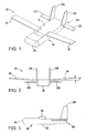
- Fig. 1 is an oblique view of an aircraft in accordance with the present invention
- Fig. 2 is a front view of the aircraft of Fig. 1 ;
- Fig. 3 is a side view of the aircraft of Fig. 1 ;
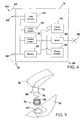
- Fig. 4 is a schematic diagram of functional parts of the fuselage of the aircraft of Fig. 1 ;
- Fig. 5 is an oblique exploded view showing components of a wing deployment system of the aircraft of Fig. 1 ;
- Figs. 6-9 are oblique views showing steps in the deployment of the wings, utilizing the wing deployment system of Fig. 5 ;
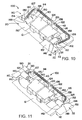
- Fig. 10 is an oblique cutaway view showing components of an elevon deployment system of the aircraft of Fig. 1 , with the elevons in a stowed configuration;
- Fig. 11 is an oblique cutaway view of the elevon deployment system of the aircraft of Fig. 10 , with the elevons in a deployed configuration;
- Figs. 12-15 are oblique views showing steps in the deployment of the elevons, utilizing the elevon deployment system of Figs. 10 and 11 ;
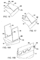
- Figs. 16-18A are oblique views showing steps in the deployment of the vertical fins of the aircraft of Fig. 1 ;
- Fig. 18B is an oblique view showing details of a locking mechanism of for the vertical fins
- Fig. 19 is an oblique view showing one configuration of a payload module that configured for use as part of the aircraft of Fig. 1 ;
- Fig. 20 is an oblique view showing another configuration of a payload module that configured for use as part of the aircraft of Fig. 1 ;
- Figs. 21-23 are oblique views showing steps in the launch of the aircraft of Fig. 1 from a launch canister;
- Fig. 24 is an oblique view showing one application of the aircraft of Fig. 1 , with the aircraft coupled to an airplane;
- Fig. 25 is an oblique view showing another application of the aircraft of Fig. 1 , with the aircraft coupled to a missile.
- An air-launched aircraft includes deployable wings, elevons, and vertical fins that deploy from a fuselage during flight.
- the aircraft includes a control system for operating the elevons, a communication system, and batteries for powering the control and communication systems.
- the aircraft may include a payload module that mates with an interface in the fuselage.
- the payload module may include any of a variety of payloads, including cameras, sensors, and/or radar emitters.
- the aircraft may be powered or unpowered, and may be very small, for example, less than on the order of 10 kg (22 pounds).
- the aircraft may be employed at a low cost for any of a wide variety of functions, such as surveillance, or as a decoy.
- the functions of the aircraft may be fulfilled during its flight, and/or after landing on the ground or other surface.
- the deployable surfaces of the aircraft may be configured to deploy in a predetermined order, allowing the aircraft automatically to enter controlled flight after being launched in a tumbling mode.
- an aircraft 10 has a fuselage 12 that has a payload module 14 coupled to it at a forward end 15 of the payload module 14.
- the aircraft 10 has a number of deployable surfaces that may be deployed during flight to produce lift and/or to control flight of the aircraft 10. These surfaces include a pair of wings 16 and 18, a pair of elevons 20 and 22, and a pair of vertical fins 26 and 28.
- the wings 16 and 18 provide lift for maintaining the flight of the aircraft 10. As best seen in Fig. 2 , the wings 16 and 18 may be canted upward, having a dihedral angle - canted wings helps maintain stability in the fuselage 12. Once deployed, wings 16 and 18 may be held fixed in place relative to the fuselage 12.
- All of the control of the aircraft 10 may be provided by the elevons 20 and 22, which are mounted on an aft end 30 of the fuselage 12. It will be appreciated that having the elevons 20 and 22 be the only control surfaces on the aircraft 10 does place some limits on the maneuverability of the aircraft 10. However, by keeping the number of movable control surfaces to a minimum, cost, weight, and complexity of the aircraft 10 may be reduced.
- the vertical fins 26 and 28 provide directional stability for the aircraft 10. As described in greater detail below, the vertical fins 26 and 28 are hinged where they join to the fuselage 12. Spring forces are used to deploy the fins 26 and 28 during flight, and to mechanically lock the fins 26 and 28 into place.
- the elevons 20 and 22 and the vertical fins 26 and 28 are collectively referred to herein as "tail surfaces.”
- Fig. 4 shows a schematic view of possible interior structures of the fuselage 12.
- the fuselage 12 may have a control system 38 that is operatively coupled to elevon actuators 40 and 42 that are used to tilt the elevons 20 and 22 to control flight of the aircraft 10.
- the control system 38 may include such devices as an inertia guidance system and a global positioning system (GPS).
- GPS global positioning system
- the controller or control system 38 also may be coupled to an electric motor 46, which may be used to turn a propeller 48.
- the propeller 48 may be located on the aft end 30 of the fuselage, in order to provide powered flight to the aircraft 10. It will be appreciated that the electric motor 46 and the propeller 48 may be optional, in that they may be excluded altogether, making the aircraft 10 a glider that flies unpowered. Thus, the aircraft 10 may engage in either unpowered or powered flight.
- a battery 50 provides power to the elevon actuators 40 and 42, the motor 46, and the control system 38.
- the battery 50 may also be used for providing power to a communication system 52 and a data collection and storage system 54.
- the battery 50 may include a variety of suitable lightweight batteries, such as nickel metal hydride batteries.
- the communication system 52 which may be coupled to the control system 38 and/or the data control system 54, may be used to communicate with systems outside of the aircraft 10. For instance, the communication system 52 may be used to communicate with ground bases, other aircraft, ships, satellites, or other suitable objects.
- the communication system 52 may be used for sending or receiving data of any of a wide variety of types.
- the communication system 52 may be used to receive data regarding control of the aircraft 10, for instance, by sending instructions or course information regarding a destination of the aircraft 10. Also, the communication system 52 may be used for sending information, such as information regarding the location of the aircraft 10, information regarding sensor readings perceived by the aircraft 10, and/or information from photographs taken by the aircraft 10. Data received and/or to be sent by the communication system 52 may be stored in the data system 54.
- the fuselage 12 includes an interface 60 on the forward end 15 of the fuselage 12.
- the interface 60 may include a mechanical interface 64 for coupling the payload module 14 ( Fig. 1 ) to the fuselage 12.
- the mechanical interface 64 may include any of a variety of types of suitable mechanical interfaces.
- the mechanical interface 64 may include a plurality of threaded holes for aligning with holes of the payload module 14, and for receiving threaded fasteners such as bolts for coupling the payload module 14 to the fuselage 12. It will be appreciated that a wide variety of other types of mechanical couplings may be utilized.
- the interface 60 may also include a data interface 66 and an electrical interface 68.
- the data interface may be coupled to the data system 54 for receiving and/or transmitting data from the data system 54 to the payload module 14.
- the electrical interface 68 may be coupled to the battery 50, so as to provide electrical power to the payload module 14.
- the aircraft 10 may have a wingspan from about 10 cm to about 2.4 m (about 4 to 96 inches).
- the weight of the aircraft 10 may be less than about 20 kg (44 pounds), may be less than about 5 kg (11 pounds), and may be less than about 2 kg (4.4 pounds). It will be appreciated that a small size and weight may be useful in allowing the aircraft 10 to be deployed from a variety of launch platforms, for example, many lightweight copies of the aircraft 10 may be stored aboard a single large aircraft, for dispersion one at a time or in groups. Also, the small size and/or light weight of the aircraft 10 may facilitate its being placed aboard relatively small other types of aircraft, such as missiles.
- the center of gravity of the aircraft 10 may be controlled to help maintain stability of the aircraft.
- the center of gravity of the aircraft 10 may be located between the wings 16 and 18.
- the aircraft 10 may have an ability to maintain flight for about 30 to 60 minutes at an altitude of approximately 9,100 meters (30,000 feet). However, it will be appreciated that the aircraft 10 may have other performance attributes.
- Fig. 5 illustrates a wing deployment system 70 for the wing 16 from a stowed position to a deployed position. It will be appreciated that a similar wing deployment system may be utilized for deploying the wing 18, and in fact, the deployment systems may be considered a single deployment system for deploying both of the wings 16 and 18.
- the wing 16 has an attached shaft 72.
- the shaft 72 is not in general perpendicular to the wing 16, but rather is angled relative to the wing 16, such that rotation of the shaft 72 about its axis shifts the wing from a stowed position, in contact with and parallel to the top of the fuselage 12, to a deployed position, at the dihedral angle ⁇ ( Fig. 2 ).
- a drive spring 76 may employ both torsion and compression forces to deploy the wing 16.
- the drive spring 76 fits around the shaft 72.
- One end of the drive spring 76 engages the hole 78 in a stepped portion 80 of the shaft 72.
- the other end of the drive spring 76 engages a hole in a recess 84 into which the drive spring 76 and the shaft 72 are placed.
- the end of the drive spring 76 may engage a bearing or other hardened portion, instead of directly engaging the fuselage 12 within the recess 84.
- the wing deployment system 70 may be configured such that the deployment of the wing 16 occurs automatically upon launch of the aircraft 10. That is, while in the stowed position, the wing 16 may be restrained only by a launch container which the aircraft is in. Once the aircraft 10 emerges from the launch container, there may be no force that constrains the wing 16 from turning about an axis of its shaft 72, under the influence of the drive spring 76 which is under torsion within the recess 84, while the wing 16 is in the stowed position.
- the locking mechanism may include any of a variety of suitable mechanical locking mechanisms, such as engagement of a protrusion or pin on one part with a corresponding recess on another part. It will be appreciated that there may be more than one wing position lock for locking the wings 16 and 18 in different positions. For example, there may be a first wing lock that temporarily locks the wings 16 and 18 in an intermediate position, between the stowed position and the deployed position, for obtaining initial stability of the aircraft 10 upon launch.
- this first wing position lock may be overcome, with the wings 16 and 18 progressing to their fully deployed position, and being locked into place there by a second position lock.
- the first wing position lock may be disengaged by any of a variety of suitable mechanisms, electro-mechanical or purely mechanical mechanisms, which may be controlled either electronically and/or mechanically.
- Figs. 6-9 show a progression of deployment of the wings 16 and 18, from a stowed position ( Fig. 6 ) to a fully deployed position ( Fig. 9).
- Figs. 7 and 8 show the wings 16 and 18 in partially deployed positions.
- intermediate locking mechanisms may be used to temporarily lock the wings 16 and 18 in the partially deployed positions.
- Fig. 10 shows an elevon deployment system 100 for deploying the elevons 20 and 22.
- the elevons 20 and 22 deploy from inside slots 110 and 112 in the fuselage 12.
- the elevons 20 and 22 are deployed through use of tension springs 114 and 116.
- the springs 114 and 116 are fixedly coupled to the fuselage 12, with hooks 120 and 122 of the springs 114 and 116 engaging pins 124 and 126 of the fuselage 12.
- the springs 114 and 116 pass around pivot pins 127 and 128, and the far ends of the springs have hooks 130 and 132 that engage respective holes 134 and 136 in bearings 140 and 142.
- the bearings 140 and 142 surround respective shafts 146 and 148 of the elevons 20 and 22.
- the shafts 146 and 148 are fixable coupled to blades 150 and 152 of the elevons 20 and 22.
- the bearings 140 and 142, and/or the elevon shafts 146 and 148 are mechanically locked to the actuator shafts 160 and 162.
- the elevons 20 and 22 may then be actuated by the servo-actuators 40 and 42.
- the servo-actuators 40 and 42 cause the actuator shafts 160 and 162 to rotate.
- the actuator shafts 160 and 162 in turn are mechanically locked with the elevon shafts 146 and 148, so movement of the actuator shafts 160 and 162 causes the elevons 20 and 22 to rotate, allowing maneuver of the aircraft 10.
- Figs. 12-15 show steps in the deployment of the elevons 20 and 22.
- Fig. 12 shows the deployed configuration, with the elevon 22 in the slot 112.
- Figs. 13 and 14 show the elevon 22 partially deployed. It will be appreciated that the elevons 20 and 22 are not rotatable to control the aircraft 10 while in the partially deployed position shown in Figs. 13 and 14 , due to portions of the elevon blades 150 and 152 still remaining in the respective slots 110 and 112.
- Fig. 15 shows the elevon 22 fully deployed, and able to be actuated by the elevon actuator 42 ( Figs. 10 and 11 ).
- the elevon shafts may be held in the opened position by the deployment spring and aerodynamic forces.
- elevon deployment systems may be used as an alternative to the elevon deployment system 100 shown in Figs. 10 and 11 and described above.
- electrical or other mechanical forces may be used to deploy the elevons 20 and 22.
- the elevon deployment system 100 described above has the virtues of simplicity and light weight.
- FIGs. 16-18B illustrate deployment of the vertical fins 26 and 28.
- the fins 26 and 28 are hingably coupled to the fuselage 12 at hinges 176 and 178.
- a fin deployment system 180 includes a pair of torsion-compression springs 186 and 188 that are used to rotate the fins 26 and 28 relative to the fuselage 12, from a stowed position to a deployed position. Once the fins 26 and 28 are in the deployed position, compression forces in the springs 186 and 188 engage rotation locks, locking the fins 26 and 28 in their deployed position.
- One end of each of the springs 186 and 188 is fixedly attached to the fuselage 12. The other end is fixedly attached to the fins 26 and 28, at or near the hinges 176 and 178.
- the springs 186 and 188 are configured such that there is a torsional force upon the fins 26 and 28 when the fins are in the stowed position. Once the fins 26 and 28 are free to move, such as when the aircraft 10 exits a storage container or launcher, the torsion forces from the springs 186 and 188 act upon the vertical fins 26 and 28 to begin rotation of the fin, as is illustrated in Fig. 17 . These torsion forces continue to act upon the vertical fins 26 and 28 until the fins reach their fully deployed position, illustrated in Fig. 18A . Once the fins 26 and 28 reach their fully deployed position, the fins 26 and 28 encounter rotation stops that prevent further rotation of the fins 26 and 28.
- Fig. 18B shows details of the locking mechanism that maintains the fin 28 in the deployed position.
- Figs. 19 and 20 show a pair of possible configurations for the payload module 14.
- the payload module 14 includes any of a variety of devices, such as sensors, cameras, or radar emitters.
- the payload module 14 may be configured to mate with the interface 60 ( Fig. 4 ), thus conforming to mechanical, electrical and/or data interface requirements of the fuselage 12.
- the payload module 14 may be configured to conform to certain requirements, such as fitting within predetermined dimensionable boundaries, and being within predetermined parameters for weight and location of center of gravity.
- the aircraft 10 may be launched from a container or launch canister 200.
- the wings 16 and 18, the elevons 20 and 22, and the vertical fins 26 and 28 are all in a stowed configuration.
- the aircraft 10 may be air-launchable in substantially any orientation relative to the flight of the platform (aircraft or missile) from which it is launched.
- the initial tumbling mode of flight may be a desirable feature in the launch of the aircraft 10. This is because the initial velocity of the aircraft 10 when air launched (for example, from about Mach 0.8 to Mach 0.95) may be so great that it would cause damage to the deployable surfaces if they were in their fully deployed positions.
- a period of tumbling during the deployment may allow the aircraft 10 to slow sufficiently such that the control and lift-producing surfaces are not damaged when they reach full deployment.
- initially launching the aircraft 10 in a tumbling mode of flight allows the lift-producing and control surfaces to be made lighter and less robust, because they encounter less stress.
- the aircraft may be initially launched in the tumbling configuration. As the tumbling slows the aircraft 10, the vertical fins 26 and 28 may be deployed. Deployment of the vertical fins 26 and 28 may aid in slowing down or stopping spinning of the aircraft 10 during the tumbling.
- the elevons 20 and 22 may be deployed to further stop the spin, and to bring the aircraft 10 into a nose down position.
- the wings 16 and 18 may be partially or fully deployed to bring the aircraft 10 into stable, controlled flight.
- the wings 16 and 18 may be deployed in two stages, with a partial deployment, such as in Figs. 7 or 8 , done first, followed by a full deployment of the wings 16 and 18 to the configuration shown in Fig. 9 .
- the deployment process of the aircraft 10 undergoes three basic regimes of flight: 1) tumbling, to initially slow down the aircraft 10 prior to full deployment of the lift-producing and control surfaces; 2) deployment of tail surfaces to stop spinning of the aircraft 10, and to bring the aircraft 10 into a nose-down configuration; and 3) deployment of the wings 16 and 18 to position the aircraft 10 into stable flight.
- the transition may involve different regimes of flight, and/or different orders of deployment of the various lift-producing and control surfaces.
- partial deployment of the wings 16 and 18 may occur during the deployment of the vertical fins 26 and 28, and/or the elevons 20 and 22.
- the order of deployment of the lift-producing and control surfaces may be controlled in any of a variety of suitable ways.
- clamps may be used to hold back certain of the lift-producing and control surfaces from immediate deployment.
- Suitable actuators such as suitable electro-mechanical actuators, may be used to control deployment of the lift-producing and control surfaces.
- the lift-producing and control surfaces may be configured on the aircraft 10 in such positions as to control their deployment.
- Fig. 24 shows one possible application of the aircraft 10.
- an airplane 220 has multiple of the aircraft 10 mounted thereupon or therewithin.
- the aircraft 10 may be launched individually or groups from the airplane 220 for any of a variety of purposes.
- the aircraft may be mounted in any of a variety of suitable places on the airplane 220.
- the aircraft 10 may be configured to launch from their launch canisters 200 in a sideways direction, relative to the airplane 220.
- the launch canisters 200 may be mechanically coupled to a fuselage 224 of the airplane 220.
- the aircraft 10 may be launched as decoys, for gathering data in the air or on the ground utilizing cameras and/or other sensors, or may be used to emit radar signals or other signals, either in the air or on the ground.
- Fig. 25 shows another possible use for the aircraft 10.
- the launch canister 200 of a camera-equipped aircraft 10 is mounted to a missile 240, such as a cruise missile.
- the aircraft 10 is launched from the canister 200.
- the aircraft 10 may be used to take a picture of the target area, and transmit it back to a receiving station (which may be ground based, air based, or sea based) to provide information regarding the target's condition.
- a receiving station which may be ground based, air based, or sea based
- the present invention provides a small, lightweight, and low cost aircraft which may be air launched for use in any of a variety of suitable missions.
- the aircraft may be flexible, in that the modular payloads can be used to configure it for any of a variety of missions.
- the aircraft may be cheap and easily expendable, allowing large numbers to be utilized for dangerous missions, such as gathering data in hostile environments.
Landscapes
- Engineering & Computer Science (AREA)
- Aviation & Aerospace Engineering (AREA)
- Remote Sensing (AREA)
- Mechanical Engineering (AREA)
- Toys (AREA)
- Tires In General (AREA)
- Radio Relay Systems (AREA)
- Details Of Aerials (AREA)
Claims (14)
- Aéronef (10) lancé en vol comportant :un fuselage (12) ;des ailes déployables (16, 18) qui sont reliées au fuselage ; etdes surfaces de commande déployables (20, 22, 26, 28) qui sont reliées au fuselage ;lequel aéronef a un poids total de moins d'environ 20 kg (44 pounds) ;dans lequel le fuselage comprend :une alimentation en énergie (50) ; etun système de commande (38) qui relié fonctionnellement à l'alimentation en énergie et aux surfaces de commande ;dans lequel les surfaces de commande déployables comprennent des élevons (20, 22) ;
dans lequel les élevons sont en arrière des ailes ; et
dans lequel les élevons se déploient depuis des fentes (110, 112) dans le fuselage. - Aéronef selon la revendication 1, dans lequel les élevons sont les seules surfaces de commande sur l'aéronef.
- Aéronef selon la revendication 1 ou la revendication 2,
dans lequel les ailes sont inclinées vers le haut ; et
dans lequel les ailes sont configurées pour se déployer depuis une position repliée par une rotation sur un seul axe autour d'arbres respectifs (72) des ailes. - Aéronef selon l'une quelconque des revendications 1 à 3, comportant en outre des dérives verticales (26, 28) reliées de façon articulée au fuselage.
- Aéronef selon l'une quelconque des revendications 1 à 4, lequel aéronef est un planeur sans moteur.
- Aéronef selon l'une quelconque des revendications 1 à 4, lequel aéronef est configuré pour un vol à l'aide d'un moteur, l'aéronef ayant une hélice mue par une batterie reliée au fuselage et à l'alimentation en énergie.
- Aéronef selon la revendication 6, dans lequel l'hélice est montée à une extrémité arrière du fuselage.
- Aéronef selon l'une quelconque des revendications 1 à 7, lequel aéronef a un poids total de moins d'environ 2 kg (4,4 pounds).
- Aéronef selon l'une quelconque des revendications 1 à 8,
comportant en outre un module (14) de charge utile relié au fuselage ;
dans lequel le fuselage comprend une interface (60) de charge utile destinée à relier la charge utile au fuselage ; et
dans lequel l'interface de charge utile comprend une interface (66) de données et une interface électrique (68). - Aéronef selon l'une quelconque des revendications 1 à 9, dans lequel les ailes sont maintenues dans une position repliée uniquement par des forces extérieures, et sont donc configurées pour se déployer automatiquement lorsque l'aéronef est lancé d'un conteneur de lancement.
- Aéronef selon l'une quelconque des revendications 1 à 10, dans lequel l'alimentation en énergie comprend au moins une batterie.
- Procédé de déploiement de l'aéronef selon l'une quelconque des revendications 1 à 11, lequel procédé comprend :le lancement de l'aéronef dans un régime de vol en culbutage ; etle fait d'amener l'aéronef dans un régime de vol commandé en déployant des surfaces de commande et des surfaces de production de portance de l'aéronef dans un ordre prédéterminé.
- Procédé selon la revendication 12, dans lequel le fait d'amener comprend :le fait de faire passer l'aéronef d'un régime de vol à culbutage à une orientation nez en bas ; etle fait de faire passer l'aéronef de l'orientation nez en bas au régime de vol commandé.
- Procédé selon la revendication 12 ou la revendication 13, dans lequel l'aéronef est lancé à une vitesse par rapport à l'air d'au moins environ Mach 0,8.
Applications Claiming Priority (2)
| Application Number | Priority Date | Filing Date | Title |
|---|---|---|---|
| US10/951,041 US7338010B2 (en) | 2004-02-07 | 2004-09-23 | Air-launchable aircraft and method of use |
| PCT/US2005/004474 WO2006036183A1 (fr) | 2004-09-23 | 2005-02-14 | Aeronef apte a etre lance en vol et son procede d'utilisation |
Publications (2)
| Publication Number | Publication Date |
|---|---|
| EP1799545A1 EP1799545A1 (fr) | 2007-06-27 |
| EP1799545B1 true EP1799545B1 (fr) | 2009-07-01 |
Family
ID=35344700
Family Applications (1)
| Application Number | Title | Priority Date | Filing Date |
|---|---|---|---|
| EP05789189A Revoked EP1799545B1 (fr) | 2004-09-23 | 2005-02-14 | Aeronef apte a etre lance en vol et son procede d'utilisation |
Country Status (7)
| Country | Link |
|---|---|
| US (1) | US7338010B2 (fr) |
| EP (1) | EP1799545B1 (fr) |
| AU (1) | AU2005290315B2 (fr) |
| CA (1) | CA2581212C (fr) |
| DE (1) | DE602005015236D1 (fr) |
| IL (1) | IL181325A (fr) |
| WO (1) | WO2006036183A1 (fr) |
Cited By (1)
| Publication number | Priority date | Publication date | Assignee | Title |
|---|---|---|---|---|
| CN103693197A (zh) * | 2013-11-29 | 2014-04-02 | 南京航空航天大学 | 一种潜射无人机 |
Families Citing this family (61)
| Publication number | Priority date | Publication date | Assignee | Title |
|---|---|---|---|---|
| US7642492B2 (en) * | 2005-01-26 | 2010-01-05 | Raytheon Company | Single-axis fin deployment system |
| US7559505B2 (en) * | 2005-12-01 | 2009-07-14 | Lockheed Martin Corporation | Apparatus and method for restraining and deploying an airfoil |
| IL178910A (en) | 2006-10-26 | 2008-04-13 | Rst Reut Systems & Advanced Te | Airborne bait that transmits radio frequencies (RF) and a method of deceiving radar-guided missiles by exploiting it |
| US9127908B2 (en) * | 2009-02-02 | 2015-09-08 | Aero Vironment, Inc. | Multimode unmanned aerial vehicle |
| IL199230A0 (en) * | 2009-06-08 | 2011-07-31 | Elta Systems Ltd | Air vehicle |
| WO2011066031A2 (fr) * | 2009-09-09 | 2011-06-03 | Aerovironment, Inc. | Système de commande d'élevon |
| JP5865247B2 (ja) | 2009-09-09 | 2016-02-17 | エアロバイロメント, インコーポレイテッドAerovironment, Inc. | 可搬型rf透過性発射筒を有する遠隔操作無人航空機レポート抑制発射機のためのシステムおよび装置 |
| WO2012119132A2 (fr) | 2011-03-02 | 2012-09-07 | Aerovironment, Inc. | Réorientation angulaire de véhicule aérien sans pilote |
| GB2490141B (en) * | 2011-04-19 | 2015-02-11 | Blue Bear Systems Res Ltd | Air Vehicle |
| CA2845094A1 (fr) | 2011-08-16 | 2013-04-18 | Unmanned Innovation Inc. | Systeme modulaire de gestion de vol integrant un pilote automatique |
| US8978534B2 (en) * | 2012-08-23 | 2015-03-17 | Emmanuel Daniel Martn Jacq | Autonomous unmanned tower military mobile intermodal container and method of using the same |
| CN102837820B (zh) * | 2012-10-09 | 2014-07-23 | 河北科技大学 | 一种z形翼布局的小型折叠翼无人机 |
| US9716862B1 (en) * | 2012-11-05 | 2017-07-25 | The Boeing Company | System and methods for capturing situational awareness |
| US12203350B2 (en) | 2013-07-18 | 2025-01-21 | DynaEnergetics Europe GmbH | Detonator positioning device |
| US9702680B2 (en) | 2013-07-18 | 2017-07-11 | Dynaenergetics Gmbh & Co. Kg | Perforation gun components and system |
| CN105492721B (zh) | 2013-08-26 | 2018-10-02 | 德国德力能有限公司 | 射孔枪和雷管组件 |
| USD710782S1 (en) * | 2013-09-05 | 2014-08-12 | Darold B. Cummings | Air vehicle having rotatable and retractable pairs of wings |
| US9776719B2 (en) * | 2013-09-05 | 2017-10-03 | Raytheon Company | Air-launchable container for deploying air vehicle |
| CA2941648C (fr) | 2014-03-07 | 2022-08-16 | Dynaenergetics Gmbh & Co. Kg | Dispositif et procede de positionnement d'un detonateur dans un ensemble perforateur |
| GB2524828A (en) * | 2014-04-04 | 2015-10-07 | Airbus Operations Ltd | An aircraft comprising a foldable aerodynamic structure and a method of manufacturing a foldable aerodynamic structure for an aircraft |
| DE102014018857B4 (de) * | 2014-12-15 | 2017-10-05 | Alfred-Wegener-Institut Helmholtz-Zentrum für Polar- und Meeresforschung | Aerodynamisch geformter, aktiver Schleppkörper |
| US9784549B2 (en) * | 2015-03-18 | 2017-10-10 | Dynaenergetics Gmbh & Co. Kg | Bulkhead assembly having a pivotable electric contact component and integrated ground apparatus |
| JP2018513809A (ja) * | 2015-04-20 | 2018-05-31 | マイケル クック,ジョージ | 空中配送のための航空機 |
| US10710715B2 (en) * | 2015-07-01 | 2020-07-14 | W.Morrison Consulting Group, Inc. | Unmanned supply delivery aircraft |
| GB2534435B (en) * | 2015-08-13 | 2017-09-06 | Wirth Res Ltd | An unmanned aerial vehicle with folding wing arrangement |
| US11958588B2 (en) | 2015-11-11 | 2024-04-16 | Anduril Industries, Inc. | Foldable propeller blade with locking mechanism |
| US9580165B1 (en) * | 2015-11-11 | 2017-02-28 | Area-I Inc. | Aerial vehicle with depolyable components |
| US11117649B2 (en) | 2015-11-11 | 2021-09-14 | Area-I Inc. | Foldable propeller blade with locking mechanism |
| US12491983B2 (en) | 2015-11-11 | 2025-12-09 | Anduril Industries, Inc. | Aerial vehicle with deployable components and configurable gearbox |
| US10358230B2 (en) * | 2016-09-12 | 2019-07-23 | Qualcomm Incorporated | Thermal arm for drone |
| US10040549B2 (en) * | 2016-09-27 | 2018-08-07 | Logistic Gliders Inc. | Single use logistic glider |
| IL300908B2 (en) | 2017-03-28 | 2025-09-01 | Anduril Industries Inc | Folding propeller blade with locking mechanism |
| WO2018236448A2 (fr) * | 2017-03-28 | 2018-12-27 | Skyworks Global Inc. | Véhicule de livraison de précision |
| US11412374B2 (en) * | 2017-09-27 | 2022-08-09 | The Boeing Company | Aircraft interface device |
| GB2568738A (en) * | 2017-11-27 | 2019-05-29 | Airbus Operations Ltd | An improved interface between an outer end of a wing and a moveable wing tip device |
| GB2572150A (en) * | 2018-03-19 | 2019-09-25 | Airbus Operations Ltd | A moveable wing tip device an outer end of a wing, and interface therebetween |
| WO2019213102A1 (fr) * | 2018-04-30 | 2019-11-07 | W. Morrison Consulting Group, Inc. | Aéronef de livraison de fournitures sans pilote |
| GB2574391A (en) * | 2018-05-31 | 2019-12-11 | Airbus Operations Ltd | An aircraft wing and wing tip device |
| US11339614B2 (en) | 2020-03-31 | 2022-05-24 | DynaEnergetics Europe GmbH | Alignment sub and orienting sub adapter |
| US11808093B2 (en) | 2018-07-17 | 2023-11-07 | DynaEnergetics Europe GmbH | Oriented perforating system |
| WO2020023166A1 (fr) * | 2018-07-27 | 2020-01-30 | Walmart Apollo, Llc | Véhicule aérien sans pilote hybride pour la livraison de marchandises |
| US11390382B1 (en) * | 2019-07-08 | 2022-07-19 | United States Of America As Represented By The Secretary Of The Air Force | Delivery system for unmanned aerial vehicles |
| US11946728B2 (en) | 2019-12-10 | 2024-04-02 | DynaEnergetics Europe GmbH | Initiator head with circuit board |
| US11988049B2 (en) | 2020-03-31 | 2024-05-21 | DynaEnergetics Europe GmbH | Alignment sub and perforating gun assembly with alignment sub |
| US20230031950A1 (en) * | 2020-04-06 | 2023-02-02 | Skyborne Technologies Pty. Ltd. | A glide bomb and methods of use thereof |
| US11525651B2 (en) * | 2020-05-15 | 2022-12-13 | Joshua Priest | Unmanned aerial vehicle with electromagnetic pulse transmitter |
| IL275576B2 (en) * | 2020-06-22 | 2023-12-01 | Israel Aerospace Ind Ltd | Wing module for an air vehicle |
| SE544263C2 (en) * | 2020-07-03 | 2022-03-22 | Saab Ab | A wing arrangement, a projectile, a method for deploying a wing blade, a use and a method for assembly |
| NO20230794A1 (en) | 2020-12-21 | 2023-07-17 | DynaEnergetics Europe GmbH | Encapsulated shaped charge |
| WO2022148557A1 (fr) | 2021-01-08 | 2022-07-14 | DynaEnergetics Europe GmbH | Ensemble perforateur à balles et composants |
| WO2022184732A1 (fr) | 2021-03-03 | 2022-09-09 | DynaEnergetics Europe GmbH | Cloison et adaptateur d'étanchéité double |
| US12366142B2 (en) | 2021-03-03 | 2025-07-22 | DynaEnergetics Europe GmbH | Modular perforating gun system |
| US11713625B2 (en) | 2021-03-03 | 2023-08-01 | DynaEnergetics Europe GmbH | Bulkhead |
| US12000267B2 (en) | 2021-09-24 | 2024-06-04 | DynaEnergetics Europe GmbH | Communication and location system for an autonomous frack system |
| US12253339B2 (en) | 2021-10-25 | 2025-03-18 | DynaEnergetics Europe GmbH | Adapter and shaped charge apparatus for optimized perforation jet |
| US12312925B2 (en) | 2021-12-22 | 2025-05-27 | DynaEnergetics Europe GmbH | Manually oriented internal shaped charge alignment system and method of use |
| CN114802706A (zh) * | 2022-05-12 | 2022-07-29 | 中国航空工业集团公司沈阳飞机设计研究所 | 一种无人机机翼展平控制方法及系统 |
| CN116552852B (zh) * | 2023-06-07 | 2025-05-30 | 西安羚控电子科技有限公司 | 一种机翼展开和上反机构以及飞行器 |
| US12546194B2 (en) | 2023-08-04 | 2026-02-10 | DynaEnergetics Europe GmbH | Method and apparatus for automatic arming of perforating gun |
| US12479574B2 (en) * | 2023-08-29 | 2025-11-25 | Rockwell Collins, Inc. | Aircraft survival kit glider |
| WO2025078425A1 (fr) * | 2023-10-09 | 2025-04-17 | Leonardo UK Ltd | Leurre |
Family Cites Families (8)
| Publication number | Priority date | Publication date | Assignee | Title |
|---|---|---|---|---|
| US3744741A (en) * | 1971-06-08 | 1973-07-10 | Celesec Ind Inc | Foldable aircraft |
| US4106727A (en) * | 1977-05-09 | 1978-08-15 | Teledyne Brown Engineering, A Division Of Teledyne Industries, Inc. | Aircraft folding airfoil system |
| DE3240903C2 (de) * | 1982-11-05 | 1984-09-13 | Dornier Gmbh, 7990 Friedrichshafen | Flugkörper mit stark gepfeiltem Tragwerk, insbesondere Deltaflügeln |
| DE3405974C1 (de) | 1984-02-18 | 1985-04-11 | Messerschmitt-Bölkow-Blohm GmbH, 8012 Ottobrunn | Aerodynamische Stabilisierungseinrichtung fuer Flugkoerper |
| US5671899A (en) * | 1996-02-26 | 1997-09-30 | Lockheed Martin Corporation | Airborne vehicle with wing extension and roll control |
| US6056237A (en) * | 1997-06-25 | 2000-05-02 | Woodland; Richard L. K. | Sonotube compatible unmanned aerial vehicle and system |
| US6392213B1 (en) * | 2000-10-12 | 2002-05-21 | The Charles Stark Draper Laboratory, Inc. | Flyer assembly |
| US6880780B1 (en) * | 2003-03-17 | 2005-04-19 | General Dynamics Ordnance And Tactical Systems, Inc. | Cover ejection and fin deployment system for a gun-launched projectile |
-
2004
- 2004-09-23 US US10/951,041 patent/US7338010B2/en not_active Expired - Lifetime
-
2005
- 2005-02-14 EP EP05789189A patent/EP1799545B1/fr not_active Revoked
- 2005-02-14 WO PCT/US2005/004474 patent/WO2006036183A1/fr not_active Ceased
- 2005-02-14 CA CA2581212A patent/CA2581212C/fr not_active Expired - Fee Related
- 2005-02-14 DE DE602005015236T patent/DE602005015236D1/de not_active Expired - Lifetime
- 2005-02-14 AU AU2005290315A patent/AU2005290315B2/en not_active Ceased
-
2007
- 2007-02-13 IL IL181325A patent/IL181325A/en active IP Right Grant
Cited By (1)
| Publication number | Priority date | Publication date | Assignee | Title |
|---|---|---|---|---|
| CN103693197A (zh) * | 2013-11-29 | 2014-04-02 | 南京航空航天大学 | 一种潜射无人机 |
Also Published As
| Publication number | Publication date |
|---|---|
| AU2005290315A1 (en) | 2006-04-06 |
| CA2581212A1 (fr) | 2006-04-06 |
| IL181325A0 (en) | 2007-07-04 |
| US20050218260A1 (en) | 2005-10-06 |
| DE602005015236D1 (de) | 2009-08-13 |
| WO2006036183A1 (fr) | 2006-04-06 |
| CA2581212C (fr) | 2010-10-12 |
| IL181325A (en) | 2010-06-30 |
| EP1799545A1 (fr) | 2007-06-27 |
| US7338010B2 (en) | 2008-03-04 |
| AU2005290315B2 (en) | 2008-07-03 |
Similar Documents
| Publication | Publication Date | Title |
|---|---|---|
| EP1799545B1 (fr) | Aeronef apte a etre lance en vol et son procede d'utilisation | |
| US20230303245A1 (en) | Unmanned supply delivery aircraft | |
| US12139257B2 (en) | Air-launched unmanned aerial vehicle | |
| US7854410B2 (en) | Powered unmanned aerial vehicle | |
| US6260797B1 (en) | Transformable gun launched aero vehicle | |
| US6142421A (en) | Vehicle refueling system | |
| US7262395B2 (en) | Expendable sonobuoy flight kit with aerodynamically assisted sonobuoy separation | |
| CN112334384B (zh) | 推进单元和包括其的飞行器 | |
| EP2212198B1 (fr) | Engin aérien VTOL sans pilote et procédé pour son pilotage | |
| US11975871B2 (en) | Rocket propelled drone | |
| US9738383B2 (en) | Remote controlled aerial reconnaissance vehicle | |
| WO2017197239A1 (fr) | Véhicules aériens sans pilote à configurations multiples | |
| US20210237872A1 (en) | Launch system | |
| US12371162B2 (en) | Payload saddle assemblies for use on aircraft | |
| EP3787968B1 (fr) | Aéronef de livraison de fournitures sans pilote | |
| KR100786313B1 (ko) | 미사일형 무인 헬리콥터 | |
| WO2025188261A1 (fr) | Aéronef autonome à parachute-voile à capacité de décollage vertical | |
| CA3006445A1 (fr) | Drone propulse par une fusee | |
| CA2606605A1 (fr) | Systeme de communications et de deploiement de trousse de vol de bouee sonore non reutilisable | |
| CA2467010C (fr) | Necessaire de vol sacrifiable pour bouee acoustique avec separation aerodynamique de la bouee | |
| CN115610653A (zh) | 一种快速拆装的串列式单兵巡飞弹 |
Legal Events
| Date | Code | Title | Description |
|---|---|---|---|
| PUAI | Public reference made under article 153(3) epc to a published international application that has entered the european phase |
Free format text: ORIGINAL CODE: 0009012 |
|
| 17P | Request for examination filed |
Effective date: 20070419 |
|
| AK | Designated contracting states |
Kind code of ref document: A1 Designated state(s): DE FR GB |
|
| DAX | Request for extension of the european patent (deleted) | ||
| RBV | Designated contracting states (corrected) |
Designated state(s): DE FR GB |
|
| 17Q | First examination report despatched |
Effective date: 20080125 |
|
| GRAP | Despatch of communication of intention to grant a patent |
Free format text: ORIGINAL CODE: EPIDOSNIGR1 |
|
| GRAS | Grant fee paid |
Free format text: ORIGINAL CODE: EPIDOSNIGR3 |
|
| GRAA | (expected) grant |
Free format text: ORIGINAL CODE: 0009210 |
|
| AK | Designated contracting states |
Kind code of ref document: B1 Designated state(s): DE FR GB |
|
| REG | Reference to a national code |
Ref country code: GB Ref legal event code: FG4D |
|
| REF | Corresponds to: |
Ref document number: 602005015236 Country of ref document: DE Date of ref document: 20090813 Kind code of ref document: P |
|
| PLBI | Opposition filed |
Free format text: ORIGINAL CODE: 0009260 |
|
| PLAX | Notice of opposition and request to file observation + time limit sent |
Free format text: ORIGINAL CODE: EPIDOSNOBS2 |
|
| 26 | Opposition filed |
Opponent name: DIEHL BGT DEFENCE GMBH & CO. KG Effective date: 20100331 |
|
| PLAF | Information modified related to communication of a notice of opposition and request to file observations + time limit |
Free format text: ORIGINAL CODE: EPIDOSCOBS2 |
|
| PLBB | Reply of patent proprietor to notice(s) of opposition received |
Free format text: ORIGINAL CODE: EPIDOSNOBS3 |
|
| REG | Reference to a national code |
Ref country code: DE Ref legal event code: R064 Ref document number: 602005015236 Country of ref document: DE Ref country code: DE Ref legal event code: R103 Ref document number: 602005015236 Country of ref document: DE |
|
| RDAF | Communication despatched that patent is revoked |
Free format text: ORIGINAL CODE: EPIDOSNREV1 |
|
| RDAG | Patent revoked |
Free format text: ORIGINAL CODE: 0009271 |
|
| STAA | Information on the status of an ep patent application or granted ep patent |
Free format text: STATUS: PATENT REVOKED |
|
| 27W | Patent revoked |
Effective date: 20111014 |
|
| GBPR | Gb: patent revoked under art. 102 of the ep convention designating the uk as contracting state |
Effective date: 20111014 |
|
| PGFP | Annual fee paid to national office [announced via postgrant information from national office to epo] |
Ref country code: FR Payment date: 20120221 Year of fee payment: 8 |
|
| PGFP | Annual fee paid to national office [announced via postgrant information from national office to epo] |
Ref country code: DE Payment date: 20120208 Year of fee payment: 8 |
|
| REG | Reference to a national code |
Ref country code: DE Ref legal event code: R107 Ref document number: 602005015236 Country of ref document: DE Effective date: 20120614 |
|
| PGFP | Annual fee paid to national office [announced via postgrant information from national office to epo] |
Ref country code: GB Payment date: 20120208 Year of fee payment: 8 |