EP1800193B1 - Procede d'exploitation d'un appareil de champ, de structure modulaire, relevant de la technique de l'automatisation - Google Patents
Procede d'exploitation d'un appareil de champ, de structure modulaire, relevant de la technique de l'automatisation Download PDFInfo
- Publication number
- EP1800193B1 EP1800193B1 EP05787208A EP05787208A EP1800193B1 EP 1800193 B1 EP1800193 B1 EP 1800193B1 EP 05787208 A EP05787208 A EP 05787208A EP 05787208 A EP05787208 A EP 05787208A EP 1800193 B1 EP1800193 B1 EP 1800193B1
- Authority
- EP
- European Patent Office
- Prior art keywords
- security code
- module
- field device
- serial number
- per
- Prior art date
- Legal status (The legal status is an assumption and is not a legal conclusion. Google has not performed a legal analysis and makes no representation as to the accuracy of the status listed.)
- Expired - Lifetime
Links
Images

Classifications
-
- G—PHYSICS
- G05—CONTROLLING; REGULATING
- G05B—CONTROL OR REGULATING SYSTEMS IN GENERAL; FUNCTIONAL ELEMENTS OF SUCH SYSTEMS; MONITORING OR TESTING ARRANGEMENTS FOR SUCH SYSTEMS OR ELEMENTS
- G05B19/00—Program-control systems
- G05B19/02—Program-control systems electric
- G05B19/418—Total factory control, i.e. centrally controlling a plurality of machines, e.g. direct or distributed numerical control [DNC], flexible manufacturing systems [FMS], integrated manufacturing systems [IMS] or computer integrated manufacturing [CIM]
- G05B19/41845—Total factory control, i.e. centrally controlling a plurality of machines, e.g. direct or distributed numerical control [DNC], flexible manufacturing systems [FMS], integrated manufacturing systems [IMS] or computer integrated manufacturing [CIM] characterised by system universality, reconfigurability, modularity
-
- Y—GENERAL TAGGING OF NEW TECHNOLOGICAL DEVELOPMENTS; GENERAL TAGGING OF CROSS-SECTIONAL TECHNOLOGIES SPANNING OVER SEVERAL SECTIONS OF THE IPC; TECHNICAL SUBJECTS COVERED BY FORMER USPC CROSS-REFERENCE ART COLLECTIONS [XRACs] AND DIGESTS
- Y02—TECHNOLOGIES OR APPLICATIONS FOR MITIGATION OR ADAPTATION AGAINST CLIMATE CHANGE
- Y02P—CLIMATE CHANGE MITIGATION TECHNOLOGIES IN THE PRODUCTION OR PROCESSING OF GOODS
- Y02P90/00—Enabling technologies with a potential contribution to greenhouse gas [GHG] emissions mitigation
- Y02P90/02—Total factory control, e.g. smart factories, flexible manufacturing systems [FMS] or integrated manufacturing systems [IMS]
Definitions
- the invention relates to a method for operating a modular field device of automation technology according to the preamble of claim 1.
- Examples of field devices are level gauges, mass flowmeters, pressure and temperature measuring devices, etc., which detect the corresponding process variables level, flow, pressure and temperature as sensors.
- Actuators such as valves or pumps, which make it possible to change the flow rate of a liquid in a pipe section or the level in a container, are used to influence the process.
- field devices are used close to the process to supply or process process-relevant information.
- Today's field devices are often modular. This allows field devices to be easily adapted to different customer requirements during production.
- Very often field devices consist of individual modules, a power supply module, an amplifier module and an input / output module, wherein the power supply module and the input / output module are usually designed as a single module.
- the functionalities of a field device are also increasingly determined by the device software (firmware) used.
- field devices In addition to basic functions, field devices often have additional software functionalities that can only be unlocked using corresponding security codes.
- the numerical values of the security codes are obtained in the field device on the basis of the serial number of the device concerned by means of mathematical algorithms. Only if the security code entered on the field device matches the value of the calculated code will the functionality belonging to this security code be unlocked.
- Security codes must normally be provided by the user directly at startup of the field device can be entered directly on the field device via a display with keyboard or via a portable operating device.
- EP 1093069 known. Under the designation F-Chip the company Endress + Hauser offers a memory chip for their field devices of the line "Proline”.
- One advantage offered by the memory chip solution for security codes is that the user can use the chip on other identically designed devices in order to unlock the same software functionalities. In particular, after a repair of a field device, if z. B. an exchange of an electronic module was required, the memory chip can continue to be used without problems.
- a memory chip provides a relatively high security against the unauthorized copying of security codes.
- An alternative to a memory chip is to store the security code permanently in a memory to which the main processor of the field device has access, and to check the validity of the code during commissioning of the device in each case.
- German patent publication DE 103 13 389 A1 a method is described for transmitting a software code or security code from a control unit to a field device, in which the software code is integrated in a device driver, eg DTM, and is transmitted to the field device with the aid of an operating program.
- a device driver eg DTM
- EP 1 093 039 A1 a possibility of protecting the software of a field device via a copy protection plug connected to an interface of the field device. Dongle, shown.
- a microcontroller is provided in the copy protection plug or dongle, which executes a control program which is used for authorization checking the access request to the software and which is protected against reading the software of the field device.
- the object of the invention is therefore to provide a method for operating a modular field device of automation technology, which does not have the disadvantages mentioned above, which in particular allows for a repair of the field device easy commissioning.
- the essential idea of the invention consists in the commissioning of Field device first to check whether an exchange of an electronic module has taken place.
- the serial number of the field device is factory-stored in each electronic module of the field device.
- Replacement modules have only one default value as a serial number z. B. 000000 on.
- a plausibility check of the serial number makes it easy to determine whether the module in question has been replaced.
- the associated software functionalities are unlocked.
- a significant advantage offered by the invention is that, even when electronic modules are replaced, normally no manual input of the security code is required when commissioning field devices.
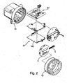
- FIG. 2 Exploded view of a modular field device
- FIG. 3 Block diagram of a field device according to Fig. 2 ;
- Fig. 5 simplified representation of the data stored in the field device after performing the method according to the invention.
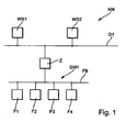
- Fig. 1 is a communication network KN of automation technology shown in more detail.
- a data bus D1 To a data bus D1 are several computer units, workstations WS 1, WS2, connected. These computer units serve as higher-level units for Process visualization, process monitoring and engineering as well as operation and monitoring of several field devices.
- the data bus D1 operates, for example, according to the Profibus DP standard or according to the HSE (High Speed Ethernet standard) of the Foundation Fieldbus. About an intermediate unit Z z.
- a controller a programmable logic controller (PLC) or a gateway, which is also referred to as Linking Device or as a segment coupler, the data bus D1 is connected to a fieldbus segment SM1.
- PLC programmable logic controller
- SM1 Linking Device
- the fieldbus segment SM1 consists of several field devices F1, F2, F3, F4, which are connected to one another via a field bus FB.
- the field devices F1, F2, F3, F4 are both sensors and actuators.
- the fieldbus operates according to one of the known communication standards of automation technology Profibus, Foundation Fieldbus or HART.
- Fig. 2 the electronics of a modular field device is shown in more detail in an exploded view.
- the device electronics essentially consists of two electronic modules; a main module, the amplifier module M1, and an I / O module, the input / output module M2.
- the modules can be connected with each other via corresponding connectors.
- For data transmission between the modules M1 and M2 is an IIC bus.
- a display operating unit 4 is provided which can be connected to the amplifier module M1 via a cable connection 5.
- the signal processing of the measurement signal supplied by the sensor essentially takes place.
- the input / output module M2 is mainly used for data communication and has different signal outputs (eg current outputs, pulse outputs) or a fieldbus interface (HART, Profibus, Foundation Fieldbus).
- the modules M1, M2 and the display control unit 4 are arranged in a housing 10 with a screw-on housing cover 12.
- Fig. 3 is a block diagram of the device electronics according to Fig. 2 shown in more detail.
- the amplifier module M1 essentially consists of a signal processing unit SE with a downstream microcontroller .mu.C.
- the signal processing unit SE which may comprise an analog / digital converter, is used for preprocessing a measurement signal which is supplied by a sensor MA (eg temperature sensor).
- a sensor MA eg temperature sensor
- the further signal processing takes place in the microcontroller ⁇ C.
- the data memory E1 is an EEPROM memory.
- the measurement information can be forwarded to higher-level units.
- the I / O unit can have a pulse output, have a frequency output or a fieldbus interface.
- the input / output module M2 also has an EEPROM memory as a data memory E2 and a power supply unit NT, which serves to supply power to the device electronics.
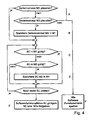
- a check is made as to whether the amplifier module M1 has been replaced.
- the memory value for the serial number of the field device is read from the data memory E1 of the module M1 and subjected to a plausibility check.
- a method step B if z. For example, if the input / output module M2 has a plausible serial number and the amplifier module M1 has no plausible serial number, the plausible serial number of the input / output module M2 is transmitted to the amplifier module M1.
- a method step C the check is carried out as to whether a valid security code SC is stored in one of the electronic modules M1 or M2. If an invalid security code SC is stored in a module, the valid security code of another module may be transferred to this module in a method step D.
- step E the software functionalities belonging to the valid software code (s) are released.
- both electronic modules M1 and M2 have an implausible serial number or security codes SC that are not valid in either module, all software functionalities that can be unlocked via security codes are blocked in a method step F.
- the invention is in the field device using a corresponding algorithm calculates a security code value from the serial number of the device.
- the calculated value of the security code is compared with the stored value of a security code. Only if both values match, is there a valid security code.
- the verification of the security code and the plausibility check of the serial number take place in the amplifier module M1, which serves as the master module. This applies, for example, to a field device with a HART interface. These devices are referred to simply as HART devices.
- the input / output module M2 is the master module.
- one or more security codes SC can only be entered via corresponding operating tools that directly access the input / output module M2 as the master module. If necessary, the input / output module M2 passes on the services addressed by the operating tool to the amplifier module M1.
- serial number SN stored in the amplifier module M1 coincides with the serial number SN stored in the input / output module M2.
- the user can immediately commission the field device. He does not have to enter any software codes by hand.
- the values of the respective master module are decisive. In this case, the data from the master module is always transferred to the other module (s).
Landscapes
- Engineering & Computer Science (AREA)
- General Engineering & Computer Science (AREA)
- Manufacturing & Machinery (AREA)
- Quality & Reliability (AREA)
- Physics & Mathematics (AREA)
- General Physics & Mathematics (AREA)
- Automation & Control Theory (AREA)
- Programmable Controllers (AREA)
- Stored Programmes (AREA)
- Storage Device Security (AREA)
- Coupling Device And Connection With Printed Circuit (AREA)
- Processing Of Terminals (AREA)
- Air Bags (AREA)
Claims (8)
- Procédé destiné à l'exploitation d'un appareil de terrain de structure modulaire de la technique d'automatisation, lequel comprend plusieurs modules électroniques M1, M2 interchangeables et possède des fonctionnalités logicielles, qui peuvent être débloquées au moyen d'un code de sécurité SC,
caractérisé par les étapes de procédé suivantes :- A. Contrôle si un échange de module a eu lieu dans l'appareil de terrain, en ce qu'au moins les numéros de série SN enregistrés dans la mémoire de données E1 du module électronique M1 sont lus et la valeur mémoire est soumise à un contrôle de plausibilité,- B. Si le module M1 ne comporte pas de numéro de série plausible et si le module M2 contient un numéro de série SN plausible, le numéro de série plausible SN est transféré dans le module électronique M1,- C. Contrôle si un code de sécurité SC valable est présent dans l'appareil de terrain, en ce qu'au moins le code de sécurité SC enregistré dans la mémoire de données E1 du module électronique M1 est lu et la valeur mémoire est comparée avec la valeur calculée du code de sécurité,- D. En présence d'un code de sécurité non valable dans le module électronique M1 et d'un code de sécurité SC valable dans le module électronique M2, le code de sécurité valable est transféré dans le module électronique M1,- E. Déblocage des fonctionnalités logicielles en fonction du/des code(s) de sécurité SC valable(s), et- F. Si aucun numéro de série plausible n'est présent, blocage de l'ensemble des fonctionnalités logicielles, qui peuvent être débloquées par le biais de codes de sécurité. - Procédé selon la revendication 1, caractérisé en ce que le code de sécurité SC dépend du numéro de série SN de l'appareil de terrain et est calculé dans l'appareil de terrain à l'aide d'un algorithme approprié, et un contrôle de présence d'un code de sécurité valable est effectué en ce que la valeur calculée du code de sécurité est comparée avec la valeur mémorisée du code de sécurité.
- Procédé selon la revendication 2, caractérisé en ce qu'un numéro de série est attribué aux modules interchangeables (p. ex. 0000000), qui est reconnaissable simplement comme étant non plausible.
- Procédé selon l'une des revendications précédentes, caractérisé en ce que l'appareil de terrain comporte au moins deux modules électroniques, un module amplificateur M1 et un module d'entrée/sortie M2.
- Procédé selon la revendication 4, caractérisé en ce que le contrôle des codes de sécurité SC et le contrôle de plausibilité des numéros de série SN s'effectuent dans un module maître.
- Procédé selon l'une des revendications précédentes, caractérisé en ce que, dans le cas d'appareils HART, le module amplificateur M1 est le module maître.
- Procédé selon l'une des revendications précédentes, caractérisé en ce que, dans le cas d'appareils Profibus, le module d'entrée/sortie M2 est le module maître.
- Procédé selon l'une des revendications précédentes, caractérisé en ce que, dans un appareil de terrain, plusieurs codes de sécurité (p. ex. SC1, SC2) sont enregistrés pour différentes fonctionnalités.
Applications Claiming Priority (2)
| Application Number | Priority Date | Filing Date | Title |
|---|---|---|---|
| DE102004049771A DE102004049771A1 (de) | 2004-10-12 | 2004-10-12 | Verfahren zum Betreiben eines modular aufgebauten Feldgerätes der Automatisierungstechnik |
| PCT/EP2005/054626 WO2006040238A1 (fr) | 2004-10-12 | 2005-09-16 | Procede d'exploitation d'un appareil de champ, de structure modulaire, relevant de la technique de l'automatisation |
Publications (2)
| Publication Number | Publication Date |
|---|---|
| EP1800193A1 EP1800193A1 (fr) | 2007-06-27 |
| EP1800193B1 true EP1800193B1 (fr) | 2009-07-01 |
Family
ID=35240880
Family Applications (1)
| Application Number | Title | Priority Date | Filing Date |
|---|---|---|---|
| EP05787208A Expired - Lifetime EP1800193B1 (fr) | 2004-10-12 | 2005-09-16 | Procede d'exploitation d'un appareil de champ, de structure modulaire, relevant de la technique de l'automatisation |
Country Status (4)
| Country | Link |
|---|---|
| EP (1) | EP1800193B1 (fr) |
| AT (1) | ATE435447T1 (fr) |
| DE (2) | DE102004049771A1 (fr) |
| WO (1) | WO2006040238A1 (fr) |
Families Citing this family (7)
| Publication number | Priority date | Publication date | Assignee | Title |
|---|---|---|---|---|
| DE102006035526A1 (de) * | 2006-07-27 | 2008-01-31 | Endress + Hauser Gmbh + Co. Kg | Verfahren zum Freischalten von Sonderfunktionalitäten bei Feldgeräten der Automatisierungstechnik |
| US7853150B2 (en) | 2007-01-05 | 2010-12-14 | Emcore Corporation | Identification and authorization of optoelectronic modules by host system |
| DE102006054421A1 (de) * | 2006-11-16 | 2008-05-21 | Endress + Hauser Gmbh + Co. Kg | Vorrichtung mit einer modular aufgebauten Messwandlerschaltung |
| US8380463B2 (en) | 2006-11-16 | 2013-02-19 | Endress + Hauser Gmbh + Co. Kg | Apparatus having a modularly constructed, measuring transducer circuit |
| DE102013206147B4 (de) * | 2013-04-08 | 2022-06-09 | Beckhoff Automation Gmbh | Dongle-Modul und Automatisierungssystem |
| DE102014111805B4 (de) | 2014-08-19 | 2023-07-20 | Krohne Messtechnik Gmbh | Vorrichtung zur Ermittlung einer Messgröße |
| DE102016009857A1 (de) * | 2016-08-12 | 2018-02-15 | WAGO Verwaltungsgesellschaft mit beschränkter Haftung | Automatische Initialisierungsroutine in einem Automatisierungs-System |
Family Cites Families (12)
| Publication number | Priority date | Publication date | Assignee | Title |
|---|---|---|---|---|
| US4965880A (en) * | 1987-07-15 | 1990-10-23 | Ciba-Geigy Corporation | Productio installation for the manufacture of a product |
| CA1318406C (fr) * | 1988-07-25 | 1993-05-25 | Anthony Gerard Gibart | Systeme d'identification modulaire de controleur programmable |
| DE4312757A1 (de) * | 1993-04-20 | 1994-10-27 | Festo Kg | Elektronische Steuereinrichtung für eine modulartig aufgebaute Ventilstation |
| DE19749853C2 (de) * | 1997-11-11 | 2000-08-24 | Siemens Ag | Verfahren zum Aktivieren unterschiedlicher Funktionen aus einer Mehrzahl von in gleichen Steuergeräten abgelegten Funktionen sowie Steuergerät |
| US6098117A (en) * | 1998-04-20 | 2000-08-01 | National Instruments Corporation | System and method for controlling access to memory configured within an I/O module in a distributed I/O system |
| DE29907265U1 (de) * | 1999-04-23 | 1999-09-16 | Siemens AG, 80333 München | Datenübertragungssystem mit selbsttätiger Konfigurierung |
| EP1093039B1 (fr) * | 1999-10-15 | 2003-11-26 | Endress + Hauser Flowtec AG | Capteur de terrain programmable |
| JP4011243B2 (ja) * | 1999-10-15 | 2007-11-21 | 富士通株式会社 | 電子原本管理装置および方法 |
| DE10218434A1 (de) * | 2002-04-25 | 2003-11-13 | Dornier Gmbh Lindauer | Verfahren zum Betrieb mehrerer Maschinenelemente einer Maschine an einem CAN-Bus |
| US6768949B2 (en) * | 2002-05-13 | 2004-07-27 | Entek Ird International Corporation | Modular equipment dynamic condition monitoring system with multiple processors |
| DE10255517A1 (de) * | 2002-11-27 | 2004-06-09 | Endress + Hauser Wetzer Gmbh + Co. Kg | Verfahren zur Identifikation eines Benutzers insbesondere bei Geräten der Prozessautomatisierungstechnik |
| DE10313389A1 (de) * | 2003-03-25 | 2004-10-07 | Endress + Hauser Process Solutions Ag | Verfahren zur Übertragung von Softwarecode von einer Steuereinheit zu einem Feldgerät der Prozessautomatisierungstechnik |
-
2004
- 2004-10-12 DE DE102004049771A patent/DE102004049771A1/de not_active Withdrawn
-
2005
- 2005-09-16 EP EP05787208A patent/EP1800193B1/fr not_active Expired - Lifetime
- 2005-09-16 WO PCT/EP2005/054626 patent/WO2006040238A1/fr not_active Ceased
- 2005-09-16 DE DE502005007634T patent/DE502005007634D1/de not_active Expired - Lifetime
- 2005-09-16 AT AT05787208T patent/ATE435447T1/de not_active IP Right Cessation
Also Published As
| Publication number | Publication date |
|---|---|
| DE502005007634D1 (de) | 2009-08-13 |
| EP1800193A1 (fr) | 2007-06-27 |
| DE102004049771A1 (de) | 2006-04-13 |
| ATE435447T1 (de) | 2009-07-15 |
| WO2006040238A1 (fr) | 2006-04-20 |
Similar Documents
| Publication | Publication Date | Title |
|---|---|---|
| EP1872180B1 (fr) | Procede de commande securisee d'un appareil de terrain de la technique d'automatisation | |
| EP1558975B1 (fr) | Procede de parametrage hors ligne d'un appareil de terrain de la technique d'automatisation des processus | |
| WO2008012164A1 (fr) | Procédé pour déconnecter des fonctionnalités particulières dans des appareils de terrain en technique d'automatisation | |
| EP3607405B1 (fr) | Procédé de paramétrage d'un appareil de terrain et appareil de terrain paramétrable | |
| EP2181367B1 (fr) | Procédé de commande d'un appareil de terrain de l'automatisation de processus disposant d'au moins deux canaux de mesure, et appareil de terrain disposant d'au moins deux canaux de mesure et adapté à la mise en oeuvre du procédé | |
| EP1631865A2 (fr) | Procede pour surveiller un dispositif a effet de champ | |
| EP1946191B1 (fr) | Procédé d'utilisation d'un appareil de terrain de la technique d'automatisation aux fonctionnalités spéciales | |
| WO2006053828A1 (fr) | Unite radio conçue pour des appareils de champ utilises en technique d'automation | |
| EP1800193B1 (fr) | Procede d'exploitation d'un appareil de champ, de structure modulaire, relevant de la technique de l'automatisation | |
| EP1682952A2 (fr) | Procede pour la maintenance de dispositifs de terrain utilises dans la technique d'automatisation des processus a l'aide d'un ordinateur de maintenance | |
| DE102004055814A1 (de) | Verfahren zur Inbetriebnahme eines Feldgerätes der Prozessautomatisierungstechnik | |
| EP1662346B1 (fr) | Procédé de paramétrisation sécurisée d'un dispositif de terrain de la technique d'automatisation | |
| EP1093039B1 (fr) | Capteur de terrain programmable | |
| WO2004006031A1 (fr) | Procede pour proteger un acces non autorise a un dispositif de terrain dans la technique d'automatisation de processus | |
| WO2017102211A1 (fr) | Clé d'accès pour appareil de terrain | |
| WO2008012243A1 (fr) | Procédé permettant de faire fonctionner un système de bus de terrain dans le contexte de la technique d'automatisation de processus | |
| DE10148029A1 (de) | Verfahren zur Datensicherung bei einem Feldgerät | |
| DE10252892A1 (de) | Verfahren zur Diagnose von Feldgeräten der Prozessautomatisierungsechnik | |
| WO2007077080A1 (fr) | Controle d'acces pour appareil de terrain en technique d'automatisation des processus | |
| EP1711870A1 (fr) | Procede de cryptage de donnees dans un reseau utilise dans la technique d'automatisation de processus | |
| DE102007062915A1 (de) | Verfahren zum Betreiben einer speicherprogrammierbaren Steuerung | |
| EP3478541B1 (fr) | Dispositif de sécurité et procédé pour faire fonctionner un système | |
| DE102023116602A1 (de) | Verfahren und System zum Autorisieren einer von einem ersten Feldgerät an ein zweites Feldgerät gesendeten Bedienaktionen | |
| WO2025056304A1 (fr) | Procédé pour chiffrer des données sur un dispositif de terrain, et procédé pour déchiffrer des données sur un dispositif de terrain |
Legal Events
| Date | Code | Title | Description |
|---|---|---|---|
| PUAI | Public reference made under article 153(3) epc to a published international application that has entered the european phase |
Free format text: ORIGINAL CODE: 0009012 |
|
| 17P | Request for examination filed |
Effective date: 20070309 |
|
| AK | Designated contracting states |
Kind code of ref document: A1 Designated state(s): AT BE BG CH CY CZ DE DK EE ES FI FR GB GR HU IE IS IT LI LT LU LV MC NL PL PT RO SE SI SK TR |
|
| 17Q | First examination report despatched |
Effective date: 20070720 |
|
| DAX | Request for extension of the european patent (deleted) | ||
| GRAP | Despatch of communication of intention to grant a patent |
Free format text: ORIGINAL CODE: EPIDOSNIGR1 |
|
| GRAS | Grant fee paid |
Free format text: ORIGINAL CODE: EPIDOSNIGR3 |
|
| GRAA | (expected) grant |
Free format text: ORIGINAL CODE: 0009210 |
|
| AK | Designated contracting states |
Kind code of ref document: B1 Designated state(s): AT BE BG CH CY CZ DE DK EE ES FI FR GB GR HU IE IS IT LI LT LU LV MC NL PL PT RO SE SI SK TR |
|
| REG | Reference to a national code |
Ref country code: GB Ref legal event code: FG4D Free format text: NOT ENGLISH |
|
| REG | Reference to a national code |
Ref country code: CH Ref legal event code: EP |
|
| REG | Reference to a national code |
Ref country code: IE Ref legal event code: FG4D |
|
| REF | Corresponds to: |
Ref document number: 502005007634 Country of ref document: DE Date of ref document: 20090813 Kind code of ref document: P |
|
| PG25 | Lapsed in a contracting state [announced via postgrant information from national office to epo] |
Ref country code: SI Free format text: LAPSE BECAUSE OF FAILURE TO SUBMIT A TRANSLATION OF THE DESCRIPTION OR TO PAY THE FEE WITHIN THE PRESCRIBED TIME-LIMIT Effective date: 20090701 |
|
| NLV1 | Nl: lapsed or annulled due to failure to fulfill the requirements of art. 29p and 29m of the patents act | ||
| PG25 | Lapsed in a contracting state [announced via postgrant information from national office to epo] |
Ref country code: SE Free format text: LAPSE BECAUSE OF FAILURE TO SUBMIT A TRANSLATION OF THE DESCRIPTION OR TO PAY THE FEE WITHIN THE PRESCRIBED TIME-LIMIT Effective date: 20090701 Ref country code: LT Free format text: LAPSE BECAUSE OF FAILURE TO SUBMIT A TRANSLATION OF THE DESCRIPTION OR TO PAY THE FEE WITHIN THE PRESCRIBED TIME-LIMIT Effective date: 20090701 Ref country code: FI Free format text: LAPSE BECAUSE OF FAILURE TO SUBMIT A TRANSLATION OF THE DESCRIPTION OR TO PAY THE FEE WITHIN THE PRESCRIBED TIME-LIMIT Effective date: 20090701 Ref country code: EE Free format text: LAPSE BECAUSE OF FAILURE TO SUBMIT A TRANSLATION OF THE DESCRIPTION OR TO PAY THE FEE WITHIN THE PRESCRIBED TIME-LIMIT Effective date: 20090701 Ref country code: ES Free format text: LAPSE BECAUSE OF FAILURE TO SUBMIT A TRANSLATION OF THE DESCRIPTION OR TO PAY THE FEE WITHIN THE PRESCRIBED TIME-LIMIT Effective date: 20091012 Ref country code: IS Free format text: LAPSE BECAUSE OF FAILURE TO SUBMIT A TRANSLATION OF THE DESCRIPTION OR TO PAY THE FEE WITHIN THE PRESCRIBED TIME-LIMIT Effective date: 20091101 |
|
| REG | Reference to a national code |
Ref country code: IE Ref legal event code: FD4D |
|
| PG25 | Lapsed in a contracting state [announced via postgrant information from national office to epo] |
Ref country code: NL Free format text: LAPSE BECAUSE OF FAILURE TO SUBMIT A TRANSLATION OF THE DESCRIPTION OR TO PAY THE FEE WITHIN THE PRESCRIBED TIME-LIMIT Effective date: 20090701 Ref country code: LV Free format text: LAPSE BECAUSE OF FAILURE TO SUBMIT A TRANSLATION OF THE DESCRIPTION OR TO PAY THE FEE WITHIN THE PRESCRIBED TIME-LIMIT Effective date: 20090701 Ref country code: PL Free format text: LAPSE BECAUSE OF FAILURE TO SUBMIT A TRANSLATION OF THE DESCRIPTION OR TO PAY THE FEE WITHIN THE PRESCRIBED TIME-LIMIT Effective date: 20090701 |
|
| BERE | Be: lapsed |
Owner name: ENDRESS + HAUSER FLOWTEC A.G. Effective date: 20090930 |
|
| PG25 | Lapsed in a contracting state [announced via postgrant information from national office to epo] |
Ref country code: BG Free format text: LAPSE BECAUSE OF FAILURE TO SUBMIT A TRANSLATION OF THE DESCRIPTION OR TO PAY THE FEE WITHIN THE PRESCRIBED TIME-LIMIT Effective date: 20091001 Ref country code: PT Free format text: LAPSE BECAUSE OF FAILURE TO SUBMIT A TRANSLATION OF THE DESCRIPTION OR TO PAY THE FEE WITHIN THE PRESCRIBED TIME-LIMIT Effective date: 20091102 |
|
| PG25 | Lapsed in a contracting state [announced via postgrant information from national office to epo] |
Ref country code: CZ Free format text: LAPSE BECAUSE OF FAILURE TO SUBMIT A TRANSLATION OF THE DESCRIPTION OR TO PAY THE FEE WITHIN THE PRESCRIBED TIME-LIMIT Effective date: 20090701 Ref country code: DK Free format text: LAPSE BECAUSE OF FAILURE TO SUBMIT A TRANSLATION OF THE DESCRIPTION OR TO PAY THE FEE WITHIN THE PRESCRIBED TIME-LIMIT Effective date: 20090701 Ref country code: RO Free format text: LAPSE BECAUSE OF FAILURE TO SUBMIT A TRANSLATION OF THE DESCRIPTION OR TO PAY THE FEE WITHIN THE PRESCRIBED TIME-LIMIT Effective date: 20090701 Ref country code: MC Free format text: LAPSE BECAUSE OF NON-PAYMENT OF DUE FEES Effective date: 20090930 Ref country code: IE Free format text: LAPSE BECAUSE OF FAILURE TO SUBMIT A TRANSLATION OF THE DESCRIPTION OR TO PAY THE FEE WITHIN THE PRESCRIBED TIME-LIMIT Effective date: 20090701 |
|
| REG | Reference to a national code |
Ref country code: CH Ref legal event code: PL |
|
| PLBE | No opposition filed within time limit |
Free format text: ORIGINAL CODE: 0009261 |
|
| STAA | Information on the status of an ep patent application or granted ep patent |
Free format text: STATUS: NO OPPOSITION FILED WITHIN TIME LIMIT |
|
| PG25 | Lapsed in a contracting state [announced via postgrant information from national office to epo] |
Ref country code: SK Free format text: LAPSE BECAUSE OF FAILURE TO SUBMIT A TRANSLATION OF THE DESCRIPTION OR TO PAY THE FEE WITHIN THE PRESCRIBED TIME-LIMIT Effective date: 20090701 |
|
| 26N | No opposition filed |
Effective date: 20100406 |
|
| REG | Reference to a national code |
Ref country code: FR Ref legal event code: ST Effective date: 20100531 |
|
| PG25 | Lapsed in a contracting state [announced via postgrant information from national office to epo] |
Ref country code: FR Free format text: LAPSE BECAUSE OF NON-PAYMENT OF DUE FEES Effective date: 20090930 |
|
| PG25 | Lapsed in a contracting state [announced via postgrant information from national office to epo] |
Ref country code: BE Free format text: LAPSE BECAUSE OF NON-PAYMENT OF DUE FEES Effective date: 20090930 |
|
| PG25 | Lapsed in a contracting state [announced via postgrant information from national office to epo] |
Ref country code: LI Free format text: LAPSE BECAUSE OF NON-PAYMENT OF DUE FEES Effective date: 20090930 Ref country code: CH Free format text: LAPSE BECAUSE OF NON-PAYMENT OF DUE FEES Effective date: 20090930 Ref country code: GR Free format text: LAPSE BECAUSE OF FAILURE TO SUBMIT A TRANSLATION OF THE DESCRIPTION OR TO PAY THE FEE WITHIN THE PRESCRIBED TIME-LIMIT Effective date: 20091002 |
|
| PG25 | Lapsed in a contracting state [announced via postgrant information from national office to epo] |
Ref country code: GB Free format text: LAPSE BECAUSE OF NON-PAYMENT OF DUE FEES Effective date: 20091001 Ref country code: AT Free format text: LAPSE BECAUSE OF NON-PAYMENT OF DUE FEES Effective date: 20090916 |
|
| PG25 | Lapsed in a contracting state [announced via postgrant information from national office to epo] |
Ref country code: IT Free format text: LAPSE BECAUSE OF FAILURE TO SUBMIT A TRANSLATION OF THE DESCRIPTION OR TO PAY THE FEE WITHIN THE PRESCRIBED TIME-LIMIT Effective date: 20090701 |
|
| PG25 | Lapsed in a contracting state [announced via postgrant information from national office to epo] |
Ref country code: LU Free format text: LAPSE BECAUSE OF NON-PAYMENT OF DUE FEES Effective date: 20090916 |
|
| PG25 | Lapsed in a contracting state [announced via postgrant information from national office to epo] |
Ref country code: HU Free format text: LAPSE BECAUSE OF FAILURE TO SUBMIT A TRANSLATION OF THE DESCRIPTION OR TO PAY THE FEE WITHIN THE PRESCRIBED TIME-LIMIT Effective date: 20100102 |
|
| PG25 | Lapsed in a contracting state [announced via postgrant information from national office to epo] |
Ref country code: TR Free format text: LAPSE BECAUSE OF FAILURE TO SUBMIT A TRANSLATION OF THE DESCRIPTION OR TO PAY THE FEE WITHIN THE PRESCRIBED TIME-LIMIT Effective date: 20090701 |
|
| PG25 | Lapsed in a contracting state [announced via postgrant information from national office to epo] |
Ref country code: CY Free format text: LAPSE BECAUSE OF FAILURE TO SUBMIT A TRANSLATION OF THE DESCRIPTION OR TO PAY THE FEE WITHIN THE PRESCRIBED TIME-LIMIT Effective date: 20090701 |
|
| P01 | Opt-out of the competence of the unified patent court (upc) registered |
Effective date: 20230601 |
|
| PGFP | Annual fee paid to national office [announced via postgrant information from national office to epo] |
Ref country code: DE Payment date: 20240918 Year of fee payment: 20 |