EP1800616B1 - Computerunterstütztes Chirurgiesystem mit Lichtquelle - Google Patents
Computerunterstütztes Chirurgiesystem mit Lichtquelle Download PDFInfo
- Publication number
- EP1800616B1 EP1800616B1 EP06256407A EP06256407A EP1800616B1 EP 1800616 B1 EP1800616 B1 EP 1800616B1 EP 06256407 A EP06256407 A EP 06256407A EP 06256407 A EP06256407 A EP 06256407A EP 1800616 B1 EP1800616 B1 EP 1800616B1
- Authority
- EP
- European Patent Office
- Prior art keywords
- light source
- image sensor
- surgeon
- light
- computer
- Prior art date
- Legal status (The legal status is an assumption and is not a legal conclusion. Google has not performed a legal analysis and makes no representation as to the accuracy of the status listed.)
- Active
Links
- 0 *CC1C2C1CCC2 Chemical compound *CC1C2C1CCC2 0.000 description 1
- ZXKBVCUVSLFOSC-UHFFFAOYSA-N C1C2C1COC2 Chemical compound C1C2C1COC2 ZXKBVCUVSLFOSC-UHFFFAOYSA-N 0.000 description 1
Images







Classifications
-
- A—HUMAN NECESSITIES
- A61—MEDICAL OR VETERINARY SCIENCE; HYGIENE
- A61B—DIAGNOSIS; SURGERY; IDENTIFICATION
- A61B17/00—Surgical instruments, devices or methods
- A61B17/14—Surgical saws
- A61B17/15—Guides therefor
- A61B17/154—Guides therefor for preparing bone for knee prosthesis
-
- A—HUMAN NECESSITIES
- A61—MEDICAL OR VETERINARY SCIENCE; HYGIENE
- A61B—DIAGNOSIS; SURGERY; IDENTIFICATION
- A61B34/00—Computer-aided surgery; Manipulators or robots specially adapted for use in surgery
- A61B34/20—Surgical navigation systems; Devices for tracking or guiding surgical instruments, e.g. for frameless stereotaxis
-
- A—HUMAN NECESSITIES
- A61—MEDICAL OR VETERINARY SCIENCE; HYGIENE
- A61B—DIAGNOSIS; SURGERY; IDENTIFICATION
- A61B90/00—Instruments, implements or accessories specially adapted for surgery or diagnosis and not covered by any of the groups A61B1/00 - A61B50/00, e.g. for luxation treatment or for protecting wound edges
- A61B90/10—Instruments, implements or accessories specially adapted for surgery or diagnosis and not covered by any of the groups A61B1/00 - A61B50/00, e.g. for luxation treatment or for protecting wound edges for stereotaxic surgery, e.g. frame-based stereotaxis
- A61B90/11—Instruments, implements or accessories specially adapted for surgery or diagnosis and not covered by any of the groups A61B1/00 - A61B50/00, e.g. for luxation treatment or for protecting wound edges for stereotaxic surgery, e.g. frame-based stereotaxis with guides for needles or instruments, e.g. arcuate slides or ball joints
- A61B90/13—Instruments, implements or accessories specially adapted for surgery or diagnosis and not covered by any of the groups A61B1/00 - A61B50/00, e.g. for luxation treatment or for protecting wound edges for stereotaxic surgery, e.g. frame-based stereotaxis with guides for needles or instruments, e.g. arcuate slides or ball joints guided by light, e.g. laser pointers
-
- A—HUMAN NECESSITIES
- A61—MEDICAL OR VETERINARY SCIENCE; HYGIENE
- A61B—DIAGNOSIS; SURGERY; IDENTIFICATION
- A61B90/00—Instruments, implements or accessories specially adapted for surgery or diagnosis and not covered by any of the groups A61B1/00 - A61B50/00, e.g. for luxation treatment or for protecting wound edges
- A61B90/30—Devices for illuminating a surgical field, the devices having an interrelation with other surgical devices or with a surgical procedure
- A61B90/35—Supports therefor
-
- A—HUMAN NECESSITIES
- A61—MEDICAL OR VETERINARY SCIENCE; HYGIENE
- A61B—DIAGNOSIS; SURGERY; IDENTIFICATION
- A61B90/00—Instruments, implements or accessories specially adapted for surgery or diagnosis and not covered by any of the groups A61B1/00 - A61B50/00, e.g. for luxation treatment or for protecting wound edges
- A61B90/36—Image-producing devices or illumination devices not otherwise provided for
-
- A—HUMAN NECESSITIES
- A61—MEDICAL OR VETERINARY SCIENCE; HYGIENE
- A61B—DIAGNOSIS; SURGERY; IDENTIFICATION
- A61B34/00—Computer-aided surgery; Manipulators or robots specially adapted for use in surgery
- A61B34/10—Computer-aided planning, simulation or modelling of surgical operations
- A61B2034/101—Computer-aided simulation of surgical operations
- A61B2034/105—Modelling of the patient, e.g. for ligaments or bones
-
- A—HUMAN NECESSITIES
- A61—MEDICAL OR VETERINARY SCIENCE; HYGIENE
- A61B—DIAGNOSIS; SURGERY; IDENTIFICATION
- A61B34/00—Computer-aided surgery; Manipulators or robots specially adapted for use in surgery
- A61B34/10—Computer-aided planning, simulation or modelling of surgical operations
- A61B2034/108—Computer aided selection or customisation of medical implants or cutting guides
-
- A—HUMAN NECESSITIES
- A61—MEDICAL OR VETERINARY SCIENCE; HYGIENE
- A61B—DIAGNOSIS; SURGERY; IDENTIFICATION
- A61B34/00—Computer-aided surgery; Manipulators or robots specially adapted for use in surgery
- A61B34/20—Surgical navigation systems; Devices for tracking or guiding surgical instruments, e.g. for frameless stereotaxis
- A61B2034/2046—Tracking techniques
- A61B2034/2055—Optical tracking systems
-
- A—HUMAN NECESSITIES
- A61—MEDICAL OR VETERINARY SCIENCE; HYGIENE
- A61B—DIAGNOSIS; SURGERY; IDENTIFICATION
- A61B34/00—Computer-aided surgery; Manipulators or robots specially adapted for use in surgery
- A61B34/20—Surgical navigation systems; Devices for tracking or guiding surgical instruments, e.g. for frameless stereotaxis
- A61B2034/2046—Tracking techniques
- A61B2034/2065—Tracking using image or pattern recognition
-
- A—HUMAN NECESSITIES
- A61—MEDICAL OR VETERINARY SCIENCE; HYGIENE
- A61B—DIAGNOSIS; SURGERY; IDENTIFICATION
- A61B34/00—Computer-aided surgery; Manipulators or robots specially adapted for use in surgery
- A61B34/20—Surgical navigation systems; Devices for tracking or guiding surgical instruments, e.g. for frameless stereotaxis
- A61B2034/2068—Surgical navigation systems; Devices for tracking or guiding surgical instruments, e.g. for frameless stereotaxis using pointers, e.g. pointers having reference marks for determining coordinates of body points
-
- A—HUMAN NECESSITIES
- A61—MEDICAL OR VETERINARY SCIENCE; HYGIENE
- A61B—DIAGNOSIS; SURGERY; IDENTIFICATION
- A61B34/00—Computer-aided surgery; Manipulators or robots specially adapted for use in surgery
- A61B34/25—User interfaces for surgical systems
- A61B2034/252—User interfaces for surgical systems indicating steps of a surgical procedure
-
- A—HUMAN NECESSITIES
- A61—MEDICAL OR VETERINARY SCIENCE; HYGIENE
- A61B—DIAGNOSIS; SURGERY; IDENTIFICATION
- A61B34/00—Computer-aided surgery; Manipulators or robots specially adapted for use in surgery
- A61B34/25—User interfaces for surgical systems
- A61B2034/254—User interfaces for surgical systems being adapted depending on the stage of the surgical procedure
-
- A—HUMAN NECESSITIES
- A61—MEDICAL OR VETERINARY SCIENCE; HYGIENE
- A61B—DIAGNOSIS; SURGERY; IDENTIFICATION
- A61B90/00—Instruments, implements or accessories specially adapted for surgery or diagnosis and not covered by any of the groups A61B1/00 - A61B50/00, e.g. for luxation treatment or for protecting wound edges
- A61B90/08—Accessories or related features not otherwise provided for
- A61B2090/0807—Indication means
-
- A—HUMAN NECESSITIES
- A61—MEDICAL OR VETERINARY SCIENCE; HYGIENE
- A61B—DIAGNOSIS; SURGERY; IDENTIFICATION
- A61B90/00—Instruments, implements or accessories specially adapted for surgery or diagnosis and not covered by any of the groups A61B1/00 - A61B50/00, e.g. for luxation treatment or for protecting wound edges
- A61B90/30—Devices for illuminating a surgical field, the devices having an interrelation with other surgical devices or with a surgical procedure
- A61B2090/309—Devices for illuminating a surgical field, the devices having an interrelation with other surgical devices or with a surgical procedure using white LEDs
-
- A—HUMAN NECESSITIES
- A61—MEDICAL OR VETERINARY SCIENCE; HYGIENE
- A61B—DIAGNOSIS; SURGERY; IDENTIFICATION
- A61B90/00—Instruments, implements or accessories specially adapted for surgery or diagnosis and not covered by any of the groups A61B1/00 - A61B50/00, e.g. for luxation treatment or for protecting wound edges
- A61B90/36—Image-producing devices or illumination devices not otherwise provided for
- A61B90/37—Surgical systems with images on a monitor during operation
- A61B2090/371—Surgical systems with images on a monitor during operation with simultaneous use of two cameras
-
- A—HUMAN NECESSITIES
- A61—MEDICAL OR VETERINARY SCIENCE; HYGIENE
- A61B—DIAGNOSIS; SURGERY; IDENTIFICATION
- A61B90/00—Instruments, implements or accessories specially adapted for surgery or diagnosis and not covered by any of the groups A61B1/00 - A61B50/00, e.g. for luxation treatment or for protecting wound edges
- A61B90/36—Image-producing devices or illumination devices not otherwise provided for
- A61B90/37—Surgical systems with images on a monitor during operation
- A61B2090/373—Surgical systems with images on a monitor during operation using light, e.g. by using optical scanners
-
- A—HUMAN NECESSITIES
- A61—MEDICAL OR VETERINARY SCIENCE; HYGIENE
- A61B—DIAGNOSIS; SURGERY; IDENTIFICATION
- A61B90/00—Instruments, implements or accessories specially adapted for surgery or diagnosis and not covered by any of the groups A61B1/00 - A61B50/00, e.g. for luxation treatment or for protecting wound edges
- A61B90/39—Markers, e.g. radio-opaque or breast lesions markers
- A61B2090/3937—Visible markers
-
- A—HUMAN NECESSITIES
- A61—MEDICAL OR VETERINARY SCIENCE; HYGIENE
- A61B—DIAGNOSIS; SURGERY; IDENTIFICATION
- A61B90/00—Instruments, implements or accessories specially adapted for surgery or diagnosis and not covered by any of the groups A61B1/00 - A61B50/00, e.g. for luxation treatment or for protecting wound edges
- A61B90/39—Markers, e.g. radio-opaque or breast lesions markers
- A61B2090/3983—Reference marker arrangements for use with image guided surgery
-
- A—HUMAN NECESSITIES
- A61—MEDICAL OR VETERINARY SCIENCE; HYGIENE
- A61B—DIAGNOSIS; SURGERY; IDENTIFICATION
- A61B34/00—Computer-aided surgery; Manipulators or robots specially adapted for use in surgery
- A61B34/10—Computer-aided planning, simulation or modelling of surgical operations
-
- A—HUMAN NECESSITIES
- A61—MEDICAL OR VETERINARY SCIENCE; HYGIENE
- A61B—DIAGNOSIS; SURGERY; IDENTIFICATION
- A61B34/00—Computer-aided surgery; Manipulators or robots specially adapted for use in surgery
- A61B34/25—User interfaces for surgical systems
-
- A—HUMAN NECESSITIES
- A61—MEDICAL OR VETERINARY SCIENCE; HYGIENE
- A61B—DIAGNOSIS; SURGERY; IDENTIFICATION
- A61B90/00—Instruments, implements or accessories specially adapted for surgery or diagnosis and not covered by any of the groups A61B1/00 - A61B50/00, e.g. for luxation treatment or for protecting wound edges
- A61B90/30—Devices for illuminating a surgical field, the devices having an interrelation with other surgical devices or with a surgical procedure
Definitions
- the present invention relates generally to computer assisted orthopaedic surgery systems.
- CAOS computer assisted orthopaedic surgery
- US-5954648 discloses an image guided surgery system which includes a camera unit, which includes a pair of cameras and a semiconductor laser light source positioned between the cameras.
- the laser light source emits a beam which is arranged to fall on the operating region so that the camera unit can be directed accurately on to the operating region.
- the invention provides a computer assisted orthopaedic surgery system as defined in claim 1.
- the system can include a controller electrically coupled to the image sensor and the light source, the controller comprising (i) a processor, and (ii) a memory device electrically coupled to the processor, the memory device having stored therein a plurality of instructions which, when executed by the processor, cause the processor to operate the light source so as to project light distinct from any ambient lighting onto the area in a pattern visually indicative of at least a portion of the field of view.
- a controller electrically coupled to the image sensor and the light source
- the controller comprising (i) a processor, and (ii) a memory device electrically coupled to the processor, the memory device having stored therein a plurality of instructions which, when executed by the processor, cause the processor to operate the light source so as to project light distinct from any ambient lighting onto the area in a pattern visually indicative of at least a portion of the field of view.
- a computer assisted orthopaedic surgery system comprises an image sensor and a light source.
- the image sensor is configured to sense an image of an area associated with an orthopaedic surgical site and has a field of view.
- the light source is secured to the image sensor to project light distinct from any ambient lighting onto the area in a pattern visually indicative of at least a portion of the field of view. Such an arrangement facilitates repositioning of the image sensor so that a desired portion of the area can be placed within the field of view for display in a relatively quick and efficient manner.
- the light source projects light onto the area in a linear pattern.
- the linear pattern may take the form of a wide variety of shapes and sizes including, but not limited to, a circle, an ellipse, a rectangle, a triangle, a polygon, any other geometric shape, or an irregular shape, to name just a few.
- the lines of the linear pattern may be solid or broken.
- the image sensor may thus be repositioned so that the desired portion of the area is within the boundaries of the linear pattern to thereby indicate to a user of the computer assisted orthopaedic system that the desired portion is within the field of view.
- the light source includes a light generator and an optical device.
- the light source generates light which is modified by the optical device into the desired pattern (linear or otherwise).
- the light generator may take the form of, for example, a laser, a laser diode, an incandescent, a fluorescent light, or the like.
- the optical device may include, but is not limited to, lenses, mirrors, fiber optics, and the like.
- the light source may be used with a variety of image sensors.
- the image sensor may be a stereoscopic camera head having two cameras arranged in stereoscopic relation or it may have only a single camera.
- FIG. 1 shows a computer assisted orthopaedic surgery (CAOS) system 10 which includes a computer 12 and a camera unit 14.
- the CAOS system 10 may be embodied as any type of computer assisted orthopaedic surgery system.
- the CAOS system 10 may be as is available under the trade mark Ci from DePuy Orthopaedics, Inc. of Warsaw, Indiana.
- the camera unit 14 may be embodied as a mobile camera unit 16 or a fixed camera unit 18. In some embodiments, the system 10 may include both types of camera units 16, 18.
- the mobile camera unit 16 includes a stand 20 coupled with a base 22.
- the base 22 may include a number of wheels 24 to allow the mobile camera unit 16 to be repositioned within a hospital room 23.
- the mobile camera unit 16 includes an image sensor 24 embodied as a camera head.
- the camera head 24 includes two cameras 26.
- the camera head 24 can be positioned relative to the stand 20 such that the field of view of the cameras 26 may be adjusted.
- the fixed camera unit 18 is similar to the mobile camera unit 16 and includes a base 28, a camera head 24, and an arm 32 coupling the camera head 24 with the base 28. In some embodiments, other peripherals, such as display screens, lights, and the like, may also be coupled with the base 28.
- the camera head 24 includes two cameras 26.
- the fixed camera unit 18 may be coupled to a ceiling, as illustratively shown in FIG. 1 , or a wall of the hospital room.
- the camera head 24 of the fixed camera unit 18 can be positioned relative to the arm 32 such that the field of view of the cameras 26 of the fixed camera unit 18 may be adjusted.
- the camera units 14, 16, 18 are communicatively coupled with the computer 12.
- the computer 12 may be mounted on or otherwise coupled with a cart 36 having a number of wheels 38 to allow the computer 12 to be positioned near the surgeon during the performance of the orthopaedic surgical procedure.
- the computer 12 illustratively includes a processor 40 and a memory device 42.
- the processor 40 may be embodied as any type of processor including, for example, discrete processing circuitry (e.g., a collection of logic devices), general purpose integrated circuit(s), and/or application specific integrated circuit(s) (i.e., ASICs).
- the memory device 42 may be embodied as any type of memory device and may include one or more memory types, such as, random access memory (i.e., RAM) and/or read-only memory (i.e., ROM).
- the computer 12 may include other devices and circuitry typically found in a computer for performing the functions described herein such as, for example, a hard drive, input/output circuitry, and the like.
- the computer 12 is communicatively coupled with a display device 44 via a communication link 46.
- the display device 44 may form a portion of the computer 12 in some embodiments. Additionally, in some embodiments, the display device 44 or an additional display device may be positioned away from the computer 12.
- the display device 44 may be coupled with the ceiling or wall of the operating room wherein the orthopaedic surgical procedure is to be performed. Additionally or alternatively, the display device 44 may be embodied as a virtual display such as a holographic display, a body mounted display such as a heads-up display, or the like.
- the computer 12 may also be coupled with a number of input devices such as a keyboard and/or a mouse for providing data input to the computer 12.
- the display device 44 is a touch-screen display device capable of receiving inputs from an orthopaedic surgeon 50. That is, the surgeon 50 can provide input data to the computer 12, such as making a selection from a number of on-screen choices, by simply touching the screen of the display device 44.
- the computer 12 is also communicatively coupled with the camera unit 16 (and/or 18) via a communication link 48.
- the communication link 48 is a wired communication link but, in some embodiments, may be embodied as a wireless communication link.
- the camera unit 16 and the computer 12 include wireless transceivers such that the computer 12 and camera unit 16 can transmit and receive data (e.g., image data).
- data e.g., image data
- the CAOS system 10 may also include a number of sensors or sensor arrays 54 which may be coupled the relevant bones of a patient 56 and/or with orthopaedic surgical tools 58.
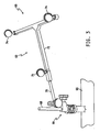
- a tibial array 60 includes a sensor array 62 and bone clamp 64.
- the illustrative bone clamp 64 is configured to be coupled with a tibia bone 66 of the patient 56 using a Schantz pin 68, but other types of bone clamps may be used.
- the sensor array 62 is coupled with the bone clamp 64 via an extension arm 70.
- the sensor array 62 includes a frame 72 and three reflective elements or sensors 74.
- the reflective elements 74 are embodied as spheres in the illustrative embodiment, but may have other geometric shapes in other embodiments. Additionally, in other embodiments sensor arrays having more than three reflective elements may be used.
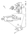
- the reflective elements 74 are positioned in a predefined configuration that allows the computer 12 to determine the identity of the tibial array 60 based on the configuration. That is, when the tibial array 60 is positioned in a field of view 52 of the camera head 24, as shown in FIG. 2 , the computer 12 is configured to determine the identity of the tibial array 60 based on the images received from the camera head 24. Additionally, based on the relative position of the reflective elements 74, the computer 12 is configured to determine the location and orientation of the tibial array 60 and, accordingly, the tibia 66 to which the array 60 is coupled.
- Sensor arrays may also be coupled to other surgical tools.
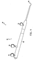
- a registration tool 80 as shown in FIG. 4 , is used to register points of a bone as discussed in more detail below in regard to FIG. 7 .
- the registration tool 80 includes a sensor array 82 having three reflective elements 84 coupled with a handle 86 of the tool 80.
- the registration tool 80 also includes pointer end 88 that is used to register points of a bone.
- the reflective elements 84 are also positioned in a configuration that allows the computer 12 to determine the identity of the registration tool 80 and its relative location (i.e., the location of the pointer end 88).
- sensor arrays may be used on other surgical tools such as a tibial resection jig 90, as illustrated in FIG. 5 .
- the jig 90 includes a resection guide portion 92 that is coupled with a tibia bone 94 at a location of the bone 94 that is to be resected.
- the jig 90 includes a sensor array 96 that is coupled with the portion 92 via a frame 95.
- the sensor array 96 includes three reflective elements 98 that are positioned in a configuration that allows the computer 12 to determine the identity of the jig 90 and its relative location (e.g., with respect to the tibia bone 94).
- the CAOS system 10 may be used by the orthopaedic surgeon 50 to assist in any type of orthopaedic surgical procedure including, for example, a total knee replacement procedure.
- the computer 12 and/or the display device 44 are positioned within the view of the surgeon 50.
- the computer 12 may be coupled with a movable cart 36 to facilitate such positioning.
- the camera unit 16 (and/or camera unit 18) is positioned such that the field of view 52 of the camera head 24 covers the portion of a patient 56 upon which the orthopaedic surgical procedure is to be performed, as shown in FIG. 2 .
- the computer 12 of the CAOS system 10 is programmed or otherwise configured to display images of the individual surgical procedure steps which form the orthopaedic surgical procedure being performed.
- the images may be graphically rendered images or graphically enhanced photographic images.
- the images may include three dimensional rendered images of the relevant anatomical portions of a patient.
- the surgeon 50 may interact with the computer 12 to display the images of the various surgical steps in sequential order.
- the surgeon may interact with the computer 12 to view previously displayed images of surgical steps, selectively view images, instruct the computer 12 to render the anatomical result of a proposed surgical step or procedure, or perform other surgical related functions.
- the surgeon may view rendered images of the resulting bone structure of different bone resection procedures.
- the CAOS system 10 provides a surgical "walk-through" for the surgeon 50 to follow while performing the orthopaedic surgical procedure.
- the surgeon 50 may also interact with the computer 12 to control various devices of the system 10.
- the surgeon 50 may interact with the system 10 to control user preferences or settings of the display device 44.
- the computer 12 may prompt the surgeon 50 for responses.
- the computer 12 may prompt the surgeon to inquire if the surgeon has completed the current surgical step, if the surgeon would like to view other images, and the like.
- the camera unit 16 and the computer 12 also cooperate to provide the surgeon with navigational data during the orthopaedic surgical procedure. That is, the computer 12 determines and displays the location of the relevant bones and the surgical tools 58 based on the data (e.g., images) received from the camera head 24 via the communication link 48. To do so, the computer 12 compares the image data received from each of the cameras 26 and determines the location and orientation of the bones and tools 58 based on the relative location and orientation of the sensor arrays 54, 62, 82, 96. The navigational data displayed to the surgeon 50 is continually updated. In this way, the CAOS system 10 provides visual feedback of the locations of relevant bones and surgical tools for the surgeon 50 to monitor while performing the orthopaedic surgical procedure.
- the CAOS system 10 provides visual feedback of the locations of relevant bones and surgical tools for the surgeon 50 to monitor while performing the orthopaedic surgical procedure.
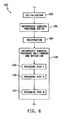
- an algorithm 100 for assisting a surgeon in performing an orthopaedic surgical procedure is executed by the computer 12.
- the algorithm 100 begins with a process step 102 in which the CAOS system 10 is initialized.
- settings, preferences, and calibrations of the CAOS system 10 are established and performed.
- the video settings of the display device 44 may be selected, the language displayed by the computer 12 may be chosen, and the touch screen of the display device 44 may be calibrated in process step 102.
- the selections and preferences of the orthopaedic surgical procedure are chosen by the surgeon. Such selections may include the type of orthopaedic surgical procedure that is to be performed (e.g., a total knee arthroplasty), the type of orthopaedic implant that will be used (e.g., make, model, size, fixation type, etc.), the sequence of operation (e.g., the tibia or the femur first), and the like.
- the orthopaedic surgical procedure Once the orthopaedic surgical procedure has been set up in process step 104, the bones of the patient are registered in process step 106. To do so, sensor arrays, such as the tibial array 60 illustrated in FIG.
- the computer 12 displays rendered images of the bones wherein the location and orientation of the bones are determined based on the sensor arrays coupled therewith and the contours of the bones are determined based on the registered points. Because only a selection of the points of the bone is registered, the computer 12 calculates and renders the remaining areas of the bones that are not registered with the tool 80.
- the computer 12 in cooperation with the camera unit 16, 18, displays the images of the surgical steps of the orthopaedic surgical procedure and associated navigation data (e.g., location of surgical tools) in process step 108.
- the process step 108 includes a number of sub-steps 110 in which each surgical procedure step is displayed to the surgeon 50 in sequential order along with the associated navigational data.
- the particular sub-steps 110 that are displayed to the surgeon 50 may depend on the selections made by the surgeon 50 in the process step 104. For example, if the surgeon 50 opted to perform a particular procedure tibia-first, the sub-steps 110 are presented to the surgeon 50 in a tibia-first order
- an algorithm 120 for assisting a surgeon in performing a total knee arthroplasty procedure may be executed by the computer 12.
- the algorithm 120 includes a process step 122 in which the CAOS system 10 is initialized.
- the process step 122 is similar to the process step 102 of the algorithm 100 described above in regard to FIG. 6 .
- the preferences of the CAOS system 10 are selected and calibrations are set.
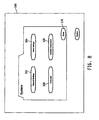
- the computer 12 displays a user initialization interface 160 to the surgeon 50 via the display device 44 as illustrated in FIG. 8 .
- the surgeon 50 may interact with the interface 160 to select various initialization options of the CAOS system 10.
- the surgeon 50 may select a network settings button 162 to change the network settings of the system 10, a video settings button 164 to change the video settings of the system 10, a language button 166 to change the language used by the system 10, and/or a calibration button 168 to change the calibrations of the touch screen of the display device 44.
- the surgeon 50 may select a button by, for example, touching an appropriate area of the touch screen of the display device 44, operating an input device such as a mouse to select the desired on-screen button, or the like.
- Additional images and/or screen displays may be displayed to the surgeon 50 during the initialization process. For example, if the surgeon 50 selects the button 162, a network setting interface may be displayed on the device 44 to allow the surgeon 50 to select different values, connections, or other options to change the network settings.
- the surgeon 50 may close the user initialization interface 160 by selecting a close button 170 and the algorithm 122 advances to the process step 124.
- process step 124 selections of the orthopaedic surgical procedure are chosen by the surgeon 50.
- the process step 124 is similar to the process step 104 of the algorithm 100 described above in regard to FIG. 6 .
- the selections made in the process step 104 may include, but are not limited to, the type of orthopaedic surgical procedure that is to be performed, the type of orthopaedic implant that will be used, and the sequence of operation, and the like.
- a number of procedure preference selection screens may be displayed to the surgeon 50 via the display device 44.
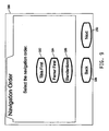
- a navigation order selection screen 180 may be displayed to the surgeon 50.
- the surgeon 50 may interact with the screen 180 to select the navigational (i.e., surgical) order of the orthopaedic surgical procedure being performed (i.e., a total knee arthroplasty procedure in the illustrative embodiment).
- the surgeon 50 may select a button 182 to instruct the controller 12 that the tibia bone of the patient 56 will be operated on first, a button 184 to instruct the controller 12 that the femur bone will be operated on first, or a button 186 to select a standardized navigation order based on, for example, the type of orthopaedic implant being used.
- the surgeon 50 may also navigate among the selection screens by a back button 188 to review previously displayed orthopaedic surgical procedure set-up screens or a next button 190 to proceed to the next orthopaedic surgical procedure set-up screen.
- the algorithm 120 advances to the process step 126.
- the relevant bones of the patient 56 are registered.
- the process step 126 is similar to the registration process step 106 of the algorithm 100.
- the process step 126 includes a number of sub-steps 128-136 in which the bones of the patient 56 involved in the orthopaedic surgical procedure are registered.
- the relevant bones are initially registered. That is, in the illustrative algorithm 120, a tibia and a femur bone of the patient 56 are initially registered. To do so, a tibia array, such as the tibia array 60 illustrated in and described above in regard to FIG. 3 , and a femur array are coupled with the respective bones.
- the tibia and femur arrays are coupled in the manner described above in regard to the tibia array 60.
- the camera head 24 of the camera unit 16 is adjusted such that the tibia and femur arrays are within the field of view 52 of the camera head 24. Once the arrays are coupled and the camera head 24 properly positioned, the tibia and femur of the patient 56 are initially registered.
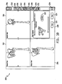
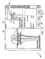
- the controller 12 displays a user interface 200 to the surgeon 50 via the display device 44, as shown in FIG. 10 .
- the interface 200 includes several navigation panes 202, 204, 206, a surgical step pane 208, and a tool bar 210.
- Navigational data is displayed to the surgeon 50 in the navigation panes 202, 204, 206.
- the computer 12 displays different views of the bone and/or surgical tools 58 in each of the panes 202, 204, 206.
- a frontal view of the patient's 56 hip and femur bone is displayed in the navigation pane 202
- a sagittal view of the patient's 56 bones is displayed in the navigation pane 204
- an oblique view of the patient's 56 bones is displayed in the navigation pane 206.
- the computer 12 displays the surgical procedure steps in the pane 208.
- the computer 12 is requesting the leg of the patient 56 be moved about in a circular motion such that the femur bone of the patient 56 is initially registered.
- the computer 12 determines the base location and orientation of the femur bone (e.g., the femur head) of the patient 56 based on the motion of the sensor array 54 coupled with the bone (i.e., based on the image data of the sensor array 54 received from the camera head 24).
- the femur bone is illustrated in FIG. 10 as being initially registered, it should be appreciated that the tibia bone is also initially registered and that other images and display screen are displayed to the surgeon 50 during such initial registration.
- the surgeon 50 can attempt to initially register the bones as many times as required by selecting a "try again" button 212. Once the relevant bones have been initially registered, the surgeon 50 can advance to the next surgical procedure step of the registration step 126 by selecting the next button 214. Alternatively, the surgeon 50 can skip one or more of the initial registration steps by selecting the button 214 and advancing to the next surgical procedure step while not performing the initial registration step (e.g., by not initially registering the femur bone of the patient 56). The surgeon 50 may also go back to the previous surgical procedure step (e.g., the initial registration of the tibia) by selecting a back button 216. In this way, the surgeon 50 can navigate through the surgical setup, registration, and procedure steps via the buttons 214, 216.
- the toolbar 210 includes a number of individual buttons, which may be selected by the surgeon 50 during the performance of the orthopaedic surgical procedure.
- the toolbar 210 includes an information button 218 that may be selected to retrieve and display information on the application software program being executed by the computer 12 such as the version number, "hotline" phone numbers, and website links.
- the toolbar 210 also includes zoom buttons 220 and 222.
- the zoom button 220 may be selected by the surgeon 50 to zoom in on the rendered images displayed in the panes 202, 204, 206 and the zoom button 222 may be used to zoom out.
- a ligament balancing button 224 may be selected to proceed to a ligament balancing procedure, which is described in more detail below in regard to process step 152.
- a 3D model button 226 may be selected to alternate between the displaying of the rendered bone (e.g., femur or tibia) and displaying only the registered points of the rendered bone in the navigation panes 202, 204, and 206.
- An implant information button 228 may be selected to display information related to an orthopaedic implant selected during later steps of the orthopaedic surgical procedure (e.g., process steps 140 and 146 described below). Such information may include, for example, the make, type, and size of the orthopaedic implant.
- a registration verification button 230 may be selected by the surgeon 50 at any time during the procedure to verify the rendered graphical model of a bone if, for example, the sensor arrays 54 coupled with the bone are accidentally bumped or otherwise moved from their fixed position.
- a screenshot button 232 may also be selected by the surgeon 50 at any time during the performance of the orthopaedic surgical procedure to record and store a screenshot of the images displayed to the surgeon 50 at that time. The screenshots 50 may be recorded in a storage device, such as a hard drive, of the computer 12.
- a close button 234 may be selected to end the current navigation and surgical procedure walk-through. After selecting the button 234, any information related to the orthopaedic surgical procedure that has been recorded, such as screenshots and other data, are stored in the storage device of the computer 12 for later retrieval and review.
- the toolbar 210 also includes a status display 236.
- the status display 236 displays different colour lights that indicate whether the system 10 can "see” or otherwise detect the sensor arrays 54 coupled with the bones and/or surgical tools.
- the status display 236 is also a button that may be selected to view a help screen illustrating a graphical rendering of the field of view 52 of the camera head 24 such that the positioning of the camera unit 16 and the sensor arrays 54 and surgical tools 58 can be monitored and adjusted if needed.
- the algorithm 120 advances to process step 130 in which the contour of the proximal tibia of the patient 56 is registered.
- the surgeon 50 uses a registration tool, such as the registration tool 80 illustrated in and described above in regard to FIG. 4 .
- the surgeon 50 registers the proximal tibia by placing the pointer end 88 of the registration tool 80 on the surface of the tibia bone as instructed in the surgical step pane 208. Contour points of the tibia bone are recorded by the computer 12 periodically as the pointer end 88 is dragged across the surface of the tibia bone and/or placed in contact with the tibia bone.
- the surgeon 50 registers enough points on the proximal tibia such that the computer 12 can determine and display a relatively accurate rendered model of the relevant portions of the tibia bone. Portions of the tibia bone that are not registered, but rather rendered by the computer 12 based on a predetermined model of the tibia bone, are displayed to the surgeon 50 in a different colour than the registered portions of the tibia bone. In this way, the surgeon 50 can monitor the registration of the tibia bone and ensure that all relevant portions of the tibia bone have been registered to improve the accuracy of the displayed model.
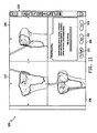
- the tibia model is calculated and verified in process step 132. To do so, the surgeon 50 follows the instructions provided in the surgical step pane 208. The proximal tibia is verified by touching the pointer end 88 of the registration tool 80 to the registered portions of the tibia bone and monitoring the distance data displayed in the pane 208 as illustrated in FIG. 12 . Based on the distance data, the surgeon 50 can determine if the current tibia model is accurate enough for the orthopaedic surgical procedure. If not, the surgeon 50 can redo the registration of the proximal tibia or supplement the registration data with additional registration points by selecting the back button 216. Once the model of the patient's 56 tibia has been determined to be sufficiently accurate, the surgeon 50 may proceed by selecting the next button 214.
- the distal femur of the patient 56 is registered next in the process step 134.
- the registration of the femur in process step 134 is similar to the registration of the tibia in the process step 130. That is, the registration tool 80 is used to registered data points on the distal femur.
- the femur model is calculated and verified in process step 136.
- the verification of the femur in process step 136 is similar to the verification of the tibia in process step 132.
- the registration tool 80 may be used to touch pre-determined portions of the femur to determine the accuracy of the femur model.
- the surgeon 50 may reregister the femur or add addition registration data points to the model by selecting the back button 216. Once the femur bone model is verified, the surgeon 50 can proceed with the orthopaedic surgical procedure by selecting the next button 214.
- process step 138 in which the computer 12 displays images of the individual surgical steps of the orthopaedic surgical procedure and the associated navigation data to the surgeon 50.
- the process step 138 includes a number of sub-steps 140-154.
- process step 140 the planning for the tibial implant is performed. Typically, the selection of the tibial implant is performed in the process step 124, but may be modified in the process step 140 depending upon how well the selected implant fits with the proximal tibia. As illustrated in FIG.
- a graphically rendered model of the tibial implant is displayed superimposed over the rendered model of the tibia bone in the navigation panes 202, 204, 206.
- the positioning of the tibial implant can be adjusted via the selection of a number of implant adjustment buttons.
- the varus/valgus rotation of the orthopaedic implant may be adjusted via the buttons 240
- the superior/inferior or proximal/distal translation of the orthopaedic implant may be adjusted via the buttons 242
- the slope of the orthopaedic implant may be adjusted via the buttons 244
- the anterior/posterior translation of the orthopaedic implant may be adjust via the buttons 246
- the internal/external rotation of the orthopaedic implant may be adjusted by the buttons 248, and the medial/lateral translation of the orthopaedic implant may be adjusted by the buttons 250.
- Data related to the positioning of the orthopaedic implant is displayed in the surgical step panel 208.
- Some attributes of the implant such as the orthopaedic implant size and thickness may be adjusted via the selection of button panels 252 and 254, respectively. Additionally the original location and orientation of the implant may be reset via selection of a reset button 256. Using the various implant adjustment buttons and the implant attribute button panels 252, 254, the surgeon 50 positions and orientates the tibial implant such that a planned resection plane 258 of the tibia bone is determined.
- surgeon 50 can see a visual rendering of the planned resection plane and the location/orientation of the tibial implant, the surgeon 50 can alter the location and orientation of the resection plane and/or tibial implant until the surgeon 50 is satisfied with the final fitting of the tibial implant to the resected proximal tibia. Once so satisfied, the surgeon 50 may proceed to the next surgical step by selecting the next button select the next button 214.
- a resection jig such as the tibial resection jig 90 illustrated in and described above in regard to FIG. 5 , is coupled with the tibia bone of the patient 56 near the desired resection location of the proximal tibia.
- the computer 12 displays the correct surgical tool to use in the present step in the surgical step pane 208.
- the computer 12 displays an actual resection plane 260 to the surgeon 50 on the navigation panes 202, 204, 206.
- a planned resection plane 258, as determined in step 140 is also displayed.
- the surgeon 50 may then adjust the coupling of the jig 90 with the tibia bone of the patient 56 such that the actual resection plane 260 overlaps or nearly overlaps the planned resection plane 258. In this way, the surgeon 50 is able to visually monitor the actual resection plane 260 while adjusting the jig 90 such that an accurate resection of the tibia can occur.
- the surgeon 50 may advance to the next surgical step by selecting the next button 214.
- the algorithm 120 advances to process step 144.
- the tibia is resected using the appropriate resection tool and the jig 90 coupled with the tibia bone of the patient 56.
- the computer 12 displays a verified resection plane 262 superimposed with the planned resection plane 258 as illustrated in FIG. 15 .
- the computer 12 also displays data related to the resection of the proximal tibia, including actual, planned, and deviation measurements, in the surgical step panel 208. In this way, the surgeon 50 can compare the final resection of the tibia and the planned resection.
- surgeon 50 can repeat the resectioning process to remove more the proximal tibia. Once the surgeon 50 is satisfied with the resection of the tibia bone, the surgeon 50 may advance to the next surgical step by selecting the next button 214.
- process step 146 the planning for the femoral implant is performed.
- the femoral implant planning of process step 146 is similar to the tibial implant planning performed in process step 124.
- the surgeon 50 positions and orients the femoral implant such that a planned resection plane of the distal femur is determined and may also select relevant implant parameters (e.g., size, type, etc.).
- surgeon 50 can see a visual rendering of the planned resection plane and the location/orientation of the femoral implant, the surgeon 50 can alter the location and orientation of the planned resection plane and/or femoral implant until the surgeon 50 is satisfied with the final fitting of the femoral implant to the resected distal femur.
- process step 148 the resectioning of the distal femur of the patient 56 is planned.
- the resection planning of the process step 148 is similar to the planning of the tibia resection performed in the process step 142.
- a femoral resection jig is coupled with the femur bone of the patient 56.
- the computer 12 displays an actual resection plane superimposed on the planned resection plane developed in process step 146. By repositioning the femoral resection jig, the surgeon 50 is able to alter the actual resection plane such that an accurate resection of the femur can occur.
- the algorithm 120 advances to process step 150 in which the distal femur is resected using the appropriate resection tool and femoral jig.
- the computer 12 displays a verified resection plane superimposed with the planned resection plane determined in process step 146. In this way, the surgeon 50 can compare the final resection of the femur with the planned resection. Again, if needed, the surgeon 50 can repeat the resectioning process to remove more the distal femur.
- process step 152 ligament balancing of the patient's 56 tibia and femur is performed. Although illustrated as occurring after the resectioning of the tibia and femur bones in FIG. 7 , ligament balancing may occur immediately following any resection step (e.g. after the tibia bone is resected) in other embodiments.
- orthopaedic implant trials i.e., temporary orthopaedic implants similar to the selected orthopaedic implants
- the computer 12 displays alignment data of the femur and tibia bone to the surgeon 50 via the display device 44. Specifically, the computer 12 displays a frontal view of the femur bone and tibia bone of the patient 56 in a frontal view pane 262 and a lateral view of the femur and tibia bones in a lateral view pane 264. Each of the panes 262, 264 display alignment data of the femur and tibia bones. Additional alignment data is displayed in the surgical step pane 208.
- the alignment data may be stored (e.g., in a data storage device included in the computer 20) by selection of a store button 266. The alignment data may subsequently be retrieved and reviewed or used in another procedure at a later time.
- Ligament balancing is performed to ensure a generally rectangular shaped extension gap and a generally rectangular shaped flexion gap at a predetermined joint force value has been established between the patient's 56 proximal tibia and the distal femur.
- a ligament balancer may be used to measure the medial and lateral joint forces and the medial and lateral gap distances when the patient's 56 leg is in extension (i.e., the patient's 56 tibia is positioned at about 0° relative to the patient's femur) and in flexion (i.e., the patient's 56 tibia is positioned at about 90° relative to the patient's femur).
- the algorithm 120 advances to process step 154 in which a final verification of the orthopaedic implants is performed.
- the orthopaedic implants are coupled with the distal femur and proximal tibia of the patient 56 and the alignment of the femur and tibia bones are verified in flexion and extension.
- the computer 12 displays the rendered images of the femur bone and tibia bone and alignment data to the surgeon 50 via the display device 44, as illustrated in FIG. 17 .
- the surgeon 50 is instructed to move the patient's 56 leg to flexion and extension such that the overall alignment can be determined and reviewed.
- the surgeon 50 may perform additional ligament balancing as discussed above in regard to process step 152.
- the surgeon 50 may store the final alignment data via selecting the store button 266. The surgeon 50 may subsequently complete the orthopaedic surgical procedure by selecting the next button 214.
- the CAOS system 10 comprising the image sensor 24 and a light source 514.
- the image sensor 24 is configured to sense an image of an area 516 associated with an orthopaedic surgical site. Further, the image sensor 24 has a field of view 52.
- the light source 514 is secured to the image sensor 24 to project light (e.g., focussed light) distinct from any ambient lighting onto the area 516 in a pattern 520 visually indicative of at least a portion of the field of view 52.
- ambient lighting is any natural or artificial white light present in the surgical area, including white task lighting that may be projected onto the area 516. Examples of such artificial lighting include room lighting (e.g., ceiling lighting, wall lighting), surgical and/or examination lighting (e.g., repositionable lighting typically brighter than the room lighting), and the like.
- the image sensor 24 may be repositionable and the light source 514 may be secured to the image sensor 24 for movement therewith in a fixed orientation relative thereto such that the light source 514 remains aligned relative to the image sensor 24 upon repositioning of the image sensor 24.
- the light source 514 is arranged relative to the image sensor 24 such that the pattern of light 520 moves with the field of view 52 in alignment therewith upon movement of the field of view 52. Stated otherwise, the position of the pattern of light 520 depends on the position of the field of view 52.
- the light pattern 520 projected by the light source 514 may or may not be coterminous with the field of view 52.
- the light pattern 520 is shown as being coterminous with the field of view 52.
- the light pattern 520 may be somewhat smaller or larger than the field of view 52 but nonetheless indicative of the field of view 52.
- the light source 514 projects light onto the area 516 in a linear pattern.
- the linear pattern may take the form of a wide variety of shapes and sizes including, but not limited to, a circle ( FIG. 19 ), a rectangle ( FIG. 20 ), a triangle a polygon, any other geometric shape, or an irregular shape, to name just a few.
- the lines of the linear pattern may be continuous or broken (e.g., dashed or dotted lines).
- the image sensor 24 may thus be repositioned so that the desired portion 522 of the area 516 is within the boundaries of the linear pattern to thereby indicate to a user of the CAOS system 10 that the desired portion 522 is within the field of view 52.
- the light source 514 includes a light generator 524 for generating the light projected therefrom onto the area 516.
- the light generator 524 may be configured, for example, as a laser or a laser diode.
- a laser pointer or laser pen may be used as the light generator 524.
- incandescent or fluorescent lighting may be used as the light generator 524.
- the colour of the light generated by the light generator 524 may be white or non-white (e.g., green, red). A non-white colour would be useful for distinguishing the light generated by the light generator 524 from room lighting or other lighting.
- An optical device 526 may be used to modify the light generated by the light generator 524 into the desired pattern 520.
- the optical device 526 may include, but is not limited to, diffractive optics, lenses, mirrors, fibre optics, and the like. It is within the scope of this disclosure to configure the optical device 526 to offer the user a plurality of light patterns from which to choose, each light pattern being indicative of the field of view 52.
- the optical device 526 may include a pattern selector operable by the user (possibly through an input device of the computer 12 or other mechanism) to selectively employ one of the light patterns from among the plurality of light patterns.
- the pattern selector may include a plurality of end caps for modifying the generated light into different shapes and/or symbols.
- the image sensor 24 may have a zoom feature for selectively zooming in or out. In such a case, the optical device 526 may be coordinated with the zoom feature of the sensor 24 to adjust the size of the pattern 520 accordingly in response to adjustment of the sensor's zoom feature.
- the image sensor 24 and the light source 514 are under the control of the computer 12 (which may be referred to as a controller).
- the computer 12 is electrically coupled to the image sensor 24 via a communication link 48 to operate the image sensor 24 and electrically coupled to the light source 514 via a communication link 548 to operate the light source 514.
- the computer 12 is also electrically coupled to a user control 528 via a communication link 530 so as to be responsive to operation of the user control 528 to cause operation of the light source 514.
- the light source 514 may be used with a variety of image sensors 24.
- the image sensor 24 may be a stereoscopic camera head having two cameras arranged in stereoscopic relation or it may have only a single camera.
- the image sensor 24 is configured, for example, as a stereoscopic camera head having two cameras 532 secured to a housing 35 of the camera head.
- the light source 514 is secured to and embedded in the housing 35 at a location between the two cameras 532 in generally fixed relation thereto.
- the housing 35 and any other mechanical components helping to secure the light source 514 to the image sensor 24 act as a movement coordinator so that the light pattern 520 moves with the field of view 52 in alignment therewith upon movement of the field of view 52.
- Other movement coordinators are within the scope of this disclosure.
- the controller 12 may, upon receipt of signals indicative of such movement, operate a device (e.g., motor and any associated drive elements) to cause coordinated movement of the light pattern 520 with the field of view 52.
- a device e.g., motor and any associated drive elements
- the light pattern 520 projected by the light source 514 is shown as being circular in FIG. 19 and rectangular in FIG. 20 but may take a variety of shapes and sizes as alluded to above.
- the camera head 24 and light source 514 secured thereto are secured to a support 536.
- the support 536 includes a first bar 538 secured to the display or base 44 and a second bar 540 secured to the first bar 538 and the camera head 24 for rotation of the head 24 and light source 514 about an axis 542 defined by the first bar 538.
- the camera head 24 is secured to the second bar 540 for rotation about an axis 544.
- a handle 546 secured to the head housing 35 can be manipulated by a user to reposition the camera head 24 and light source 514 relative to the base 44. To do so, the user grips the handle 546 and operates a user control 548 secured thereto. Such operation of the user control 548 unlocks the head 24 and light source 514 for movement relative to the base 44. The computer 12 detects such unlocking and operates the light source 514 to cause generation of light thereby in response to detection of the unlocking of the head 24 and light source 514. Thus, operation of the user control 548 simultaneously causes the computer 12 to operate the light source 514 to provide the user a visual indication of the field of view 52.
- a user can reposition the camera 24 and indicator 516 in a variety of directions such as, for example, direction 550 ( FIG. 19 ) to move the field of view 52 and light pattern 520 from a position shown, for example, in FIG. 22a in a direction 552 to a position shown, for example, in FIG. 22b in which the desired portion 522 of the area 516 is within the field of view 52.
- the light pattern 520 is not coterminous with the field of view 52 as suggested by the circular light pattern 520 within the generally square field of view 52 in FIGS. 22a and 22b .
- the light pattern 520 may or may not be coterminous with the field of view 52.
- the circular shape of the field of view 52 and light pattern 520 shown in FIGS. 22a and 22b is shown merely as one example of the many different shapes and sizes possible for the field of view 58 and light pattern 520.
- the handle 546 causes the head 24 and light source 514 to be relocked in place and causes the computer 12 to deactivate the light source 514 to cease generation of light by the light generator 524.
- the user control 548 may be, for example, a pressure-sensitive switch embedded in the grip portion of the handle 546.
- the display is included in the base 44.
- the base 44 may be configured in many different ways that may or may not include the display.
- the base 44 may take the form of the base 22.
- the base 44 may be embodied as an attachment to the floor, wall, ceiling, or other structure and may be fixed or movable relative thereto.
Landscapes
- Health & Medical Sciences (AREA)
- Surgery (AREA)
- Life Sciences & Earth Sciences (AREA)
- Engineering & Computer Science (AREA)
- General Health & Medical Sciences (AREA)
- Veterinary Medicine (AREA)
- Nuclear Medicine, Radiotherapy & Molecular Imaging (AREA)
- Public Health (AREA)
- Animal Behavior & Ethology (AREA)
- Molecular Biology (AREA)
- Biomedical Technology (AREA)
- Heart & Thoracic Surgery (AREA)
- Medical Informatics (AREA)
- Oral & Maxillofacial Surgery (AREA)
- Pathology (AREA)
- Physical Education & Sports Medicine (AREA)
- Transplantation (AREA)
- Orthopedic Medicine & Surgery (AREA)
- Dentistry (AREA)
- Physics & Mathematics (AREA)
- Optics & Photonics (AREA)
- Robotics (AREA)
- Surgical Instruments (AREA)
Claims (8)
- Computerunterstützes System für orthopädische Chirurgie, umfassend:einen Halter (38, 540),einen Bildsensor (532), der konfiguriert ist, um ein Bild von einem Gebiet aufzunehmen, das mit einer orthopädischen Operationsstelle verbunden ist, wobei der Bildsensor ein Sichtfeld (52) aufweist,eine an dem Bildsensor gesicherte Lichtquelle zum Projizieren von Licht, das sich von irgendeiner Umgebungsbeleuchtung unterscheidet, auf das Gebiet in einem Muster (520), das zumindest einen Teil des Sichtfeldes optisch anzeigt,ein Gehäuse (35), das mit dem Halter (538, 540) verbunden ist, wobei der Bildsensor (532) und die Lichtquelle (514) an dem Gehäuse gesichert sind,dadurch gekenntzeichnet, dass das System einen Handgriff (546) enthält, mittels dessen das Gehäuse mit dem Bildsensor und der Lichtquelle von einem Benutzer gehandhabt werden kann, um den Bildsensor und die Lichtquelle relativ zum Halter neu zu positionieren, so dass die Lichtquelle bei Neupositionierung des Bildsensors relativ zum Bildsensor ausgerichtet bleibt,wobei das System eine Bedienersteuerung (548) enthält, die an dem Handgriff gesichert ist und bei Betätigung durch einen Benutzer (a) den Bildsensor und die Lichtquelle freigibt, so dass sie relativ zum Halter bewegt werden können, und (b) die Lichtquelle zum Erzeugen von Licht aktiviert.
- System nach Anspruch 1, in dem die Lichtquelle (514) konfiguriert ist, um ein lineares Muster (520) von Licht auf das Gebiet zu projizieren.
- System nach Anspruch 1, in dem die Lichtquelle (514) einen Laser oder eine Laserdiode aufweist.
- System nach Anspruch 1, in dem die Lichtquelle (514) eine optische Einrichtung aufweist, die konfiguriert ist, um das von der Lichtquelle erzeugte Licht in das Muster (520), das das Sehfeld (52) anzeigt, umzuwandeln.
- System nach Anspruch 1, in dem der Bildsensor eine erste Kamera (532) aufweist.
- System nach Anspruch 5, in dem der Bildsensor eine zweite Kamera (532) enthält, die in stereoskopischer Beziehung zur ersten Kamera positioniert ist, und die Lichtquelle (514) zwischen der ersten Kamera und der zweiten Kamera angeordnet ist.
- System nach Anspruch 1, in dem die Lichtquelle (14) relativ zum Bildsensor (532) so angeordnet ist, dass die Position des Lichtmusters von der Position des Sichtfeldes abhängt.
- System nach Anspruch 1, das eine Steuerung enthält, die mit dem Bildsensor (532) und der Lichtquelle (514) elektrisch gekoppelt ist, wobei die Steuerung umfasst: (i) einen Prozessor und (ii) eine Speichereinrichtung, die mit dem Prozessor elektrisch gekoppelt ist, wobei die Speichereinrichtung eine Vielzahl von Anweisungen speichert, die bei Ausführung durch den Prozessor dafür sorgen, dass der Prozessor die Lichtquelle betreibt.
Applications Claiming Priority (1)
| Application Number | Priority Date | Filing Date | Title |
|---|---|---|---|
| US11/319,817 US7894872B2 (en) | 2005-12-26 | 2005-12-26 | Computer assisted orthopaedic surgery system with light source and associated method |
Publications (2)
| Publication Number | Publication Date |
|---|---|
| EP1800616A1 EP1800616A1 (de) | 2007-06-27 |
| EP1800616B1 true EP1800616B1 (de) | 2011-07-27 |
Family
ID=37891844
Family Applications (1)
| Application Number | Title | Priority Date | Filing Date |
|---|---|---|---|
| EP06256407A Active EP1800616B1 (de) | 2005-12-26 | 2006-12-16 | Computerunterstütztes Chirurgiesystem mit Lichtquelle |
Country Status (3)
| Country | Link |
|---|---|
| US (1) | US7894872B2 (de) |
| EP (1) | EP1800616B1 (de) |
| AT (1) | ATE517585T1 (de) |
Cited By (1)
| Publication number | Priority date | Publication date | Assignee | Title |
|---|---|---|---|---|
| US10022065B2 (en) | 2014-11-30 | 2018-07-17 | Elbit Systems Ltd. | Model registration system and method |
Families Citing this family (59)
| Publication number | Priority date | Publication date | Assignee | Title |
|---|---|---|---|---|
| WO2003034705A2 (en) * | 2001-10-19 | 2003-04-24 | University Of North Carolina At Chapel Hill | Methods and systems for dynamic virtual convergence and head mountable display |
| US20070225590A1 (en) * | 2006-01-13 | 2007-09-27 | Boston Scientific Scimed, Inc. | Control panel for a medical imaging system |
| US9636188B2 (en) * | 2006-03-24 | 2017-05-02 | Stryker Corporation | System and method for 3-D tracking of surgical instrument in relation to patient body |
| US8560047B2 (en) | 2006-06-16 | 2013-10-15 | Board Of Regents Of The University Of Nebraska | Method and apparatus for computer aided surgery |
| US20110057930A1 (en) * | 2006-07-26 | 2011-03-10 | Inneroptic Technology Inc. | System and method of using high-speed, high-resolution depth extraction to provide three-dimensional imagery for endoscopy |
| WO2008017051A2 (en) | 2006-08-02 | 2008-02-07 | Inneroptic Technology Inc. | System and method of providing real-time dynamic imagery of a medical procedure site using multiple modalities |
| DE502006002276D1 (de) * | 2006-10-26 | 2009-01-15 | Brainlab Ag | Integriertes medizinisches Trackingsystem |
| KR100916638B1 (ko) * | 2007-08-02 | 2009-09-08 | 인하대학교 산학협력단 | 구조광을 이용한 토공량 산출 장치 및 방법 |
| WO2009089629A1 (en) * | 2008-01-16 | 2009-07-23 | Orthosoft Inc. | Pinless technique for computer assisted orthopedic surgery |
| WO2009094646A2 (en) * | 2008-01-24 | 2009-07-30 | The University Of North Carolina At Chapel Hill | Methods, systems, and computer readable media for image guided ablation |
| US9665686B2 (en) | 2008-02-20 | 2017-05-30 | Mako Surgical Corp. | Implant planning using corrected captured joint motion information |
| US8340379B2 (en) | 2008-03-07 | 2012-12-25 | Inneroptic Technology, Inc. | Systems and methods for displaying guidance data based on updated deformable imaging data |
| CA2716550C (en) * | 2008-03-25 | 2019-07-16 | Orthosoft Ulc | Method and system for planning/guiding alterations to a bone |
| US20090312629A1 (en) * | 2008-06-13 | 2009-12-17 | Inneroptic Technology Inc. | Correction of relative tracking errors based on a fiducial |
| EP2156805B1 (de) | 2008-08-20 | 2012-11-14 | BrainLAB AG | Planungsunterstützung für die Korrektur von Gelenkelementen |
| US8641621B2 (en) | 2009-02-17 | 2014-02-04 | Inneroptic Technology, Inc. | Systems, methods, apparatuses, and computer-readable media for image management in image-guided medical procedures |
| US11464578B2 (en) | 2009-02-17 | 2022-10-11 | Inneroptic Technology, Inc. | Systems, methods, apparatuses, and computer-readable media for image management in image-guided medical procedures |
| US8690776B2 (en) | 2009-02-17 | 2014-04-08 | Inneroptic Technology, Inc. | Systems, methods, apparatuses, and computer-readable media for image guided surgery |
| US8554307B2 (en) | 2010-04-12 | 2013-10-08 | Inneroptic Technology, Inc. | Image annotation in image-guided medical procedures |
| US8556830B2 (en) | 2009-03-31 | 2013-10-15 | Depuy | Device and method for displaying joint force data |
| US8721568B2 (en) | 2009-03-31 | 2014-05-13 | Depuy (Ireland) | Method for performing an orthopaedic surgical procedure |
| US8740817B2 (en) | 2009-03-31 | 2014-06-03 | Depuy (Ireland) | Device and method for determining forces of a patient's joint |
| US8597210B2 (en) * | 2009-03-31 | 2013-12-03 | Depuy (Ireland) | System and method for displaying joint force data |
| US8551023B2 (en) | 2009-03-31 | 2013-10-08 | Depuy (Ireland) | Device and method for determining force of a knee joint |
| US20110043612A1 (en) * | 2009-07-31 | 2011-02-24 | Inneroptic Technology Inc. | Dual-tube stereoscope |
| US8579922B2 (en) * | 2009-10-05 | 2013-11-12 | Covidien Lp | Method of suture identification and mesh marking for orienting and locating a mesh during hernia repair |
| US20110082351A1 (en) * | 2009-10-07 | 2011-04-07 | Inneroptic Technology, Inc. | Representing measurement information during a medical procedure |
| US9282947B2 (en) | 2009-12-01 | 2016-03-15 | Inneroptic Technology, Inc. | Imager focusing based on intraoperative data |
| US9847044B1 (en) * | 2011-01-03 | 2017-12-19 | Smith & Nephew Orthopaedics Ag | Surgical implement training process |
| US9498231B2 (en) | 2011-06-27 | 2016-11-22 | Board Of Regents Of The University Of Nebraska | On-board tool tracking system and methods of computer assisted surgery |
| US11911117B2 (en) | 2011-06-27 | 2024-02-27 | Board Of Regents Of The University Of Nebraska | On-board tool tracking system and methods of computer assisted surgery |
| WO2013052187A2 (en) | 2011-06-27 | 2013-04-11 | Board Of Regents Of The University Of Nebraska | On-board tool tracking system and methods of computer assisted surgery |
| US20130041266A1 (en) * | 2011-08-12 | 2013-02-14 | Tyco Healthcare Group Lp, | System and Method for Indicating Positioning of an Internal Anatomical Feature |
| US8971989B2 (en) | 2012-01-24 | 2015-03-03 | Covidien Lp | Magnetic field device for mapping and navigation in laparoscopic surgery |
| US8670816B2 (en) | 2012-01-30 | 2014-03-11 | Inneroptic Technology, Inc. | Multiple medical device guidance |
| US9381011B2 (en) | 2012-03-29 | 2016-07-05 | Depuy (Ireland) | Orthopedic surgical instrument for knee surgery |
| US10070973B2 (en) | 2012-03-31 | 2018-09-11 | Depuy Ireland Unlimited Company | Orthopaedic sensor module and system for determining joint forces of a patient's knee joint |
| US10206792B2 (en) | 2012-03-31 | 2019-02-19 | Depuy Ireland Unlimited Company | Orthopaedic surgical system for determining joint forces of a patients knee joint |
| EP2732788A1 (de) * | 2012-11-19 | 2014-05-21 | Metronor AS | System zur Ermöglichung einer präzisen Platzierung eines Implantats in einem Patienten während eines chirurgischen Eingriffs |
| US10314559B2 (en) | 2013-03-14 | 2019-06-11 | Inneroptic Technology, Inc. | Medical device guidance |
| US10105149B2 (en) | 2013-03-15 | 2018-10-23 | Board Of Regents Of The University Of Nebraska | On-board tool tracking system and methods of computer assisted surgery |
| US20170000497A1 (en) | 2013-11-29 | 2017-01-05 | The Johns Hopkins University | Cranial reference mount |
| US9901406B2 (en) | 2014-10-02 | 2018-02-27 | Inneroptic Technology, Inc. | Affected region display associated with a medical device |
| US10603175B2 (en) | 2014-11-24 | 2020-03-31 | The Johns Hopkins University | Cutting machine for resizing raw implants during surgery |
| AU2015353523B2 (en) | 2014-11-24 | 2019-10-24 | The Johns Hopkins University | Computer-assisted cranioplasty |
| US12178520B2 (en) | 2014-11-30 | 2024-12-31 | Elbit Systems Ltd. | Model registration system and method |
| US10188467B2 (en) | 2014-12-12 | 2019-01-29 | Inneroptic Technology, Inc. | Surgical guidance intersection display |
| US9949700B2 (en) | 2015-07-22 | 2018-04-24 | Inneroptic Technology, Inc. | Medical device approaches |
| US11058541B2 (en) | 2015-09-04 | 2021-07-13 | The Johns Hopkins University | Low-profile intercranial device |
| US10085645B2 (en) | 2015-09-30 | 2018-10-02 | DePuy Synthes Products, Inc. | Implant placement method with feedback |
| US9675319B1 (en) | 2016-02-17 | 2017-06-13 | Inneroptic Technology, Inc. | Loupe display |
| US10278778B2 (en) | 2016-10-27 | 2019-05-07 | Inneroptic Technology, Inc. | Medical device navigation using a virtual 3D space |
| FI20175247A7 (fi) | 2017-03-17 | 2018-09-18 | Planmeca Oy | Hammashoitokoneen operaatiovalaisin |
| US11259879B2 (en) | 2017-08-01 | 2022-03-01 | Inneroptic Technology, Inc. | Selective transparency to assist medical device navigation |
| US10695109B2 (en) | 2017-12-13 | 2020-06-30 | DePuy Synthes Products, Inc. | Intramedullary nail with cannulation access hole |
| US11484365B2 (en) | 2018-01-23 | 2022-11-01 | Inneroptic Technology, Inc. | Medical image guidance |
| JP7714518B2 (ja) * | 2019-07-08 | 2025-07-29 | ストライカー コーポレイション | 目標スペクトル照明のためのシステムおよび方法 |
| KR20210051141A (ko) | 2019-10-30 | 2021-05-10 | 주식회사 스키아 | 환자의 증강 현실 기반의 의료 정보를 제공하는 방법, 장치 및 컴퓨터 프로그램 |
| WO2023177785A1 (en) | 2022-03-17 | 2023-09-21 | Mako Surgical Corp. | Techniques for securing together components of one or more surgical carts |
Family Cites Families (7)
| Publication number | Priority date | Publication date | Assignee | Title |
|---|---|---|---|---|
| US2990765A (en) * | 1956-12-01 | 1961-07-04 | Kamera & Kinowerke Dresden Veb | Stereo camera for scientific and surgical photography |
| US6405072B1 (en) | 1991-01-28 | 2002-06-11 | Sherwood Services Ag | Apparatus and method for determining a location of an anatomical target with reference to a medical apparatus |
| KR0137861B1 (ko) | 1991-07-15 | 1998-05-15 | 강진구 | 레이저 빔을 이용한 촬영 영역 표시 회로 |
| GB9405299D0 (en) | 1994-03-17 | 1994-04-27 | Roke Manor Research | Improvements in or relating to video-based systems for computer assisted surgery and localisation |
| US5973728A (en) * | 1994-05-09 | 1999-10-26 | Airway Cam Technologies, Inc. | Direct laryngoscopy video system |
| JP3792257B2 (ja) * | 1996-04-29 | 2006-07-05 | ノーザン・デジタル・インコーポレーテッド | 画像誘導手術システム |
| US6715904B2 (en) * | 2001-07-19 | 2004-04-06 | Michael L. Naughton | Laser light handle |
-
2005
- 2005-12-26 US US11/319,817 patent/US7894872B2/en active Active
-
2006
- 2006-12-16 AT AT06256407T patent/ATE517585T1/de not_active IP Right Cessation
- 2006-12-16 EP EP06256407A patent/EP1800616B1/de active Active
Cited By (1)
| Publication number | Priority date | Publication date | Assignee | Title |
|---|---|---|---|---|
| US10022065B2 (en) | 2014-11-30 | 2018-07-17 | Elbit Systems Ltd. | Model registration system and method |
Also Published As
| Publication number | Publication date |
|---|---|
| US20070167701A1 (en) | 2007-07-19 |
| US7894872B2 (en) | 2011-02-22 |
| ATE517585T1 (de) | 2011-08-15 |
| EP1800616A1 (de) | 2007-06-27 |
Similar Documents
| Publication | Publication Date | Title |
|---|---|---|
| US7894872B2 (en) | Computer assisted orthopaedic surgery system with light source and associated method | |
| US11928625B2 (en) | System and method for performing a computer assisted orthopaedic surgical procedure | |
| US12350002B2 (en) | Soft tissue cutting instrument and method of use | |
| US12515336B2 (en) | Robotic surgical system with motorized movement to a starting pose for a registration or calibration routine | |
| EP1769771A1 (de) | Computer-assistiertes System für die orthopädische Chirurgie | |
| US7885701B2 (en) | Registration pointer and method for registering a bone of a patient to a computer assisted orthopaedic surgery system | |
| JP4754215B2 (ja) | コンピュータ支援膝関節形成術の器具類、システム、および方法 | |
| US8876830B2 (en) | Virtual implant placement in the OR | |
| JP2007531596A (ja) | 基準アレイ入力装置を提供する方法及び装置 | |
| JP2007518540A (ja) | 患者に対して取り付けられた外科手術ナビゲーションセンサを提供するための方法およびシステムおよび装置 | |
| US20050279368A1 (en) | Computer assisted surgery input/output systems and processes | |
| US20080021283A1 (en) | Apparatus and method for retracting tissue of a patient during an orthopaedic surgical procedure | |
| JP2007260404A (ja) | 患者の運動学上の動作をモニターするためのシステムおよび方法 | |
| US20060084863A1 (en) | Positional verification | |
| US20250277580A1 (en) | Methods for kinematic alignment in navigated total knee arthroplasty (tka) | |
| Kamil et al. | P5. 3-Machine-Vision-Based and Inertial-Sensor-Supported Navigation System for the Minimal Invasive Surgery |
Legal Events
| Date | Code | Title | Description |
|---|---|---|---|
| PUAI | Public reference made under article 153(3) epc to a published international application that has entered the european phase |
Free format text: ORIGINAL CODE: 0009012 |
|
| AK | Designated contracting states |
Kind code of ref document: A1 Designated state(s): AT BE BG CH CY CZ DE DK EE ES FI FR GB GR HU IE IS IT LI LT LU LV MC NL PL PT RO SE SI SK TR |
|
| AX | Request for extension of the european patent |
Extension state: AL BA HR MK YU |
|
| 17P | Request for examination filed |
Effective date: 20071113 |
|
| AKX | Designation fees paid |
Designated state(s): AT BE BG CH CY CZ DE DK EE ES FI FR GB GR HU IE IS IT LI LT LU LV MC NL PL PT RO SE SI SK TR |
|
| 17Q | First examination report despatched |
Effective date: 20081203 |
|
| GRAP | Despatch of communication of intention to grant a patent |
Free format text: ORIGINAL CODE: EPIDOSNIGR1 |
|
| GRAC | Information related to communication of intention to grant a patent modified |
Free format text: ORIGINAL CODE: EPIDOSCIGR1 |
|
| GRAS | Grant fee paid |
Free format text: ORIGINAL CODE: EPIDOSNIGR3 |
|
| GRAA | (expected) grant |
Free format text: ORIGINAL CODE: 0009210 |
|
| AK | Designated contracting states |
Kind code of ref document: B1 Designated state(s): AT BE BG CH CY CZ DE DK EE ES FI FR GB GR HU IE IS IT LI LT LU LV MC NL PL PT RO SE SI SK TR |
|
| REG | Reference to a national code |
Ref country code: GB Ref legal event code: FG4D |
|
| REG | Reference to a national code |
Ref country code: CH Ref legal event code: NV Representative=s name: E. BLUM & CO. AG PATENT- UND MARKENANWAELTE VSP Ref country code: CH Ref legal event code: EP |
|
| REG | Reference to a national code |
Ref country code: DE Ref legal event code: R096 Ref document number: 602006023292 Country of ref document: DE Effective date: 20110915 |
|
| REG | Reference to a national code |
Ref country code: NL Ref legal event code: VDEP Effective date: 20110727 |
|
| REG | Reference to a national code |
Ref country code: AT Ref legal event code: MK05 Ref document number: 517585 Country of ref document: AT Kind code of ref document: T Effective date: 20110727 |
|
| PG25 | Lapsed in a contracting state [announced via postgrant information from national office to epo] |
Ref country code: SE Free format text: LAPSE BECAUSE OF FAILURE TO SUBMIT A TRANSLATION OF THE DESCRIPTION OR TO PAY THE FEE WITHIN THE PRESCRIBED TIME-LIMIT Effective date: 20110727 Ref country code: NL Free format text: LAPSE BECAUSE OF FAILURE TO SUBMIT A TRANSLATION OF THE DESCRIPTION OR TO PAY THE FEE WITHIN THE PRESCRIBED TIME-LIMIT Effective date: 20110727 Ref country code: FI Free format text: LAPSE BECAUSE OF FAILURE TO SUBMIT A TRANSLATION OF THE DESCRIPTION OR TO PAY THE FEE WITHIN THE PRESCRIBED TIME-LIMIT Effective date: 20110727 Ref country code: IS Free format text: LAPSE BECAUSE OF FAILURE TO SUBMIT A TRANSLATION OF THE DESCRIPTION OR TO PAY THE FEE WITHIN THE PRESCRIBED TIME-LIMIT Effective date: 20111127 Ref country code: PT Free format text: LAPSE BECAUSE OF FAILURE TO SUBMIT A TRANSLATION OF THE DESCRIPTION OR TO PAY THE FEE WITHIN THE PRESCRIBED TIME-LIMIT Effective date: 20111128 Ref country code: BE Free format text: LAPSE BECAUSE OF FAILURE TO SUBMIT A TRANSLATION OF THE DESCRIPTION OR TO PAY THE FEE WITHIN THE PRESCRIBED TIME-LIMIT Effective date: 20110727 Ref country code: LT Free format text: LAPSE BECAUSE OF FAILURE TO SUBMIT A TRANSLATION OF THE DESCRIPTION OR TO PAY THE FEE WITHIN THE PRESCRIBED TIME-LIMIT Effective date: 20110727 |
|
| PG25 | Lapsed in a contracting state [announced via postgrant information from national office to epo] |
Ref country code: PL Free format text: LAPSE BECAUSE OF FAILURE TO SUBMIT A TRANSLATION OF THE DESCRIPTION OR TO PAY THE FEE WITHIN THE PRESCRIBED TIME-LIMIT Effective date: 20110727 Ref country code: LV Free format text: LAPSE BECAUSE OF FAILURE TO SUBMIT A TRANSLATION OF THE DESCRIPTION OR TO PAY THE FEE WITHIN THE PRESCRIBED TIME-LIMIT Effective date: 20110727 Ref country code: SI Free format text: LAPSE BECAUSE OF FAILURE TO SUBMIT A TRANSLATION OF THE DESCRIPTION OR TO PAY THE FEE WITHIN THE PRESCRIBED TIME-LIMIT Effective date: 20110727 Ref country code: GR Free format text: LAPSE BECAUSE OF FAILURE TO SUBMIT A TRANSLATION OF THE DESCRIPTION OR TO PAY THE FEE WITHIN THE PRESCRIBED TIME-LIMIT Effective date: 20111028 Ref country code: AT Free format text: LAPSE BECAUSE OF FAILURE TO SUBMIT A TRANSLATION OF THE DESCRIPTION OR TO PAY THE FEE WITHIN THE PRESCRIBED TIME-LIMIT Effective date: 20110727 Ref country code: CY Free format text: LAPSE BECAUSE OF FAILURE TO SUBMIT A TRANSLATION OF THE DESCRIPTION OR TO PAY THE FEE WITHIN THE PRESCRIBED TIME-LIMIT Effective date: 20110727 |
|
| PG25 | Lapsed in a contracting state [announced via postgrant information from national office to epo] |
Ref country code: CZ Free format text: LAPSE BECAUSE OF FAILURE TO SUBMIT A TRANSLATION OF THE DESCRIPTION OR TO PAY THE FEE WITHIN THE PRESCRIBED TIME-LIMIT Effective date: 20110727 Ref country code: SK Free format text: LAPSE BECAUSE OF FAILURE TO SUBMIT A TRANSLATION OF THE DESCRIPTION OR TO PAY THE FEE WITHIN THE PRESCRIBED TIME-LIMIT Effective date: 20110727 |
|
| PG25 | Lapsed in a contracting state [announced via postgrant information from national office to epo] |
Ref country code: IT Free format text: LAPSE BECAUSE OF FAILURE TO SUBMIT A TRANSLATION OF THE DESCRIPTION OR TO PAY THE FEE WITHIN THE PRESCRIBED TIME-LIMIT Effective date: 20110727 Ref country code: EE Free format text: LAPSE BECAUSE OF FAILURE TO SUBMIT A TRANSLATION OF THE DESCRIPTION OR TO PAY THE FEE WITHIN THE PRESCRIBED TIME-LIMIT Effective date: 20110727 Ref country code: RO Free format text: LAPSE BECAUSE OF FAILURE TO SUBMIT A TRANSLATION OF THE DESCRIPTION OR TO PAY THE FEE WITHIN THE PRESCRIBED TIME-LIMIT Effective date: 20110727 |
|
| PLBE | No opposition filed within time limit |
Free format text: ORIGINAL CODE: 0009261 |
|
| STAA | Information on the status of an ep patent application or granted ep patent |
Free format text: STATUS: NO OPPOSITION FILED WITHIN TIME LIMIT |
|
| PG25 | Lapsed in a contracting state [announced via postgrant information from national office to epo] |
Ref country code: DK Free format text: LAPSE BECAUSE OF FAILURE TO SUBMIT A TRANSLATION OF THE DESCRIPTION OR TO PAY THE FEE WITHIN THE PRESCRIBED TIME-LIMIT Effective date: 20110727 |
|
| 26N | No opposition filed |
Effective date: 20120502 |
|
| PG25 | Lapsed in a contracting state [announced via postgrant information from national office to epo] |
Ref country code: MC Free format text: LAPSE BECAUSE OF NON-PAYMENT OF DUE FEES Effective date: 20111231 |
|
| REG | Reference to a national code |
Ref country code: DE Ref legal event code: R097 Ref document number: 602006023292 Country of ref document: DE Effective date: 20120502 |
|
| PG25 | Lapsed in a contracting state [announced via postgrant information from national office to epo] |
Ref country code: ES Free format text: LAPSE BECAUSE OF FAILURE TO SUBMIT A TRANSLATION OF THE DESCRIPTION OR TO PAY THE FEE WITHIN THE PRESCRIBED TIME-LIMIT Effective date: 20111107 |
|
| PG25 | Lapsed in a contracting state [announced via postgrant information from national office to epo] |
Ref country code: LU Free format text: LAPSE BECAUSE OF NON-PAYMENT OF DUE FEES Effective date: 20111216 |
|
| PG25 | Lapsed in a contracting state [announced via postgrant information from national office to epo] |
Ref country code: BG Free format text: LAPSE BECAUSE OF FAILURE TO SUBMIT A TRANSLATION OF THE DESCRIPTION OR TO PAY THE FEE WITHIN THE PRESCRIBED TIME-LIMIT Effective date: 20111027 |
|
| PG25 | Lapsed in a contracting state [announced via postgrant information from national office to epo] |
Ref country code: TR Free format text: LAPSE BECAUSE OF FAILURE TO SUBMIT A TRANSLATION OF THE DESCRIPTION OR TO PAY THE FEE WITHIN THE PRESCRIBED TIME-LIMIT Effective date: 20110727 |
|
| PG25 | Lapsed in a contracting state [announced via postgrant information from national office to epo] |
Ref country code: HU Free format text: LAPSE BECAUSE OF FAILURE TO SUBMIT A TRANSLATION OF THE DESCRIPTION OR TO PAY THE FEE WITHIN THE PRESCRIBED TIME-LIMIT Effective date: 20110727 |
|
| REG | Reference to a national code |
Ref country code: FR Ref legal event code: PLFP Year of fee payment: 11 |
|
| REG | Reference to a national code |
Ref country code: FR Ref legal event code: PLFP Year of fee payment: 12 |
|
| REG | Reference to a national code |
Ref country code: CH Ref legal event code: U11 Free format text: ST27 STATUS EVENT CODE: U-0-0-U10-U11 (AS PROVIDED BY THE NATIONAL OFFICE) Effective date: 20260101 |
|
| PGFP | Annual fee paid to national office [announced via postgrant information from national office to epo] |
Ref country code: DE Payment date: 20251028 Year of fee payment: 20 |
|
| PGFP | Annual fee paid to national office [announced via postgrant information from national office to epo] |
Ref country code: GB Payment date: 20251030 Year of fee payment: 20 |
|
| PGFP | Annual fee paid to national office [announced via postgrant information from national office to epo] |
Ref country code: FR Payment date: 20251110 Year of fee payment: 20 |
|
| PGFP | Annual fee paid to national office [announced via postgrant information from national office to epo] |
Ref country code: IE Payment date: 20251111 Year of fee payment: 20 |
|
| PGFP | Annual fee paid to national office [announced via postgrant information from national office to epo] |
Ref country code: CH Payment date: 20260101 Year of fee payment: 20 |