EP1800731B1 - Concentrateur d'oxygène médical portable - Google Patents
Concentrateur d'oxygène médical portable Download PDFInfo
- Publication number
- EP1800731B1 EP1800731B1 EP06025927.2A EP06025927A EP1800731B1 EP 1800731 B1 EP1800731 B1 EP 1800731B1 EP 06025927 A EP06025927 A EP 06025927A EP 1800731 B1 EP1800731 B1 EP 1800731B1
- Authority
- EP
- European Patent Office
- Prior art keywords
- product
- column
- adsorbent
- port
- portable medical
- Prior art date
- Legal status (The legal status is an assumption and is not a legal conclusion. Google has not performed a legal analysis and makes no representation as to the accuracy of the status listed.)
- Active
Links
Images






Classifications
-
- B—PERFORMING OPERATIONS; TRANSPORTING
- B01—PHYSICAL OR CHEMICAL PROCESSES OR APPARATUS IN GENERAL
- B01D—SEPARATION
- B01D53/00—Separation of gases or vapours; Recovering vapours of volatile solvents from gases; Chemical or biological purification of waste gases, e.g. engine exhaust gases, smoke, fumes, flue gases, aerosols
- B01D53/02—Separation of gases or vapours; Recovering vapours of volatile solvents from gases; Chemical or biological purification of waste gases, e.g. engine exhaust gases, smoke, fumes, flue gases, aerosols by adsorption, e.g. preparative gas chromatography
- B01D53/04—Separation of gases or vapours; Recovering vapours of volatile solvents from gases; Chemical or biological purification of waste gases, e.g. engine exhaust gases, smoke, fumes, flue gases, aerosols by adsorption, e.g. preparative gas chromatography with stationary adsorbents
- B01D53/0407—Constructional details of adsorbing systems
- B01D53/0415—Beds in cartridges
-
- B—PERFORMING OPERATIONS; TRANSPORTING
- B01—PHYSICAL OR CHEMICAL PROCESSES OR APPARATUS IN GENERAL
- B01D—SEPARATION
- B01D53/00—Separation of gases or vapours; Recovering vapours of volatile solvents from gases; Chemical or biological purification of waste gases, e.g. engine exhaust gases, smoke, fumes, flue gases, aerosols
- B01D53/02—Separation of gases or vapours; Recovering vapours of volatile solvents from gases; Chemical or biological purification of waste gases, e.g. engine exhaust gases, smoke, fumes, flue gases, aerosols by adsorption, e.g. preparative gas chromatography
- B01D53/04—Separation of gases or vapours; Recovering vapours of volatile solvents from gases; Chemical or biological purification of waste gases, e.g. engine exhaust gases, smoke, fumes, flue gases, aerosols by adsorption, e.g. preparative gas chromatography with stationary adsorbents
- B01D53/0407—Constructional details of adsorbing systems
- B01D53/0446—Means for feeding or distributing gases
-
- B—PERFORMING OPERATIONS; TRANSPORTING
- B01—PHYSICAL OR CHEMICAL PROCESSES OR APPARATUS IN GENERAL
- B01D—SEPARATION
- B01D2256/00—Main component in the product gas stream after treatment
- B01D2256/12—Oxygen
-
- B—PERFORMING OPERATIONS; TRANSPORTING
- B01—PHYSICAL OR CHEMICAL PROCESSES OR APPARATUS IN GENERAL
- B01D—SEPARATION
- B01D2259/00—Type of treatment
- B01D2259/40—Further details for adsorption processes and devices
- B01D2259/40003—Methods relating to valve switching
- B01D2259/40005—Methods relating to valve switching using rotary valves
-
- B—PERFORMING OPERATIONS; TRANSPORTING
- B01—PHYSICAL OR CHEMICAL PROCESSES OR APPARATUS IN GENERAL
- B01D—SEPARATION
- B01D2259/00—Type of treatment
- B01D2259/45—Gas separation or purification devices adapted for specific applications
- B01D2259/4533—Gas separation or purification devices adapted for specific applications for medical purposes
-
- B—PERFORMING OPERATIONS; TRANSPORTING
- B01—PHYSICAL OR CHEMICAL PROCESSES OR APPARATUS IN GENERAL
- B01D—SEPARATION
- B01D2259/00—Type of treatment
- B01D2259/45—Gas separation or purification devices adapted for specific applications
- B01D2259/4541—Gas separation or purification devices adapted for specific applications for portable use, e.g. gas masks
-
- B—PERFORMING OPERATIONS; TRANSPORTING
- B01—PHYSICAL OR CHEMICAL PROCESSES OR APPARATUS IN GENERAL
- B01D—SEPARATION
- B01D53/00—Separation of gases or vapours; Recovering vapours of volatile solvents from gases; Chemical or biological purification of waste gases, e.g. engine exhaust gases, smoke, fumes, flue gases, aerosols
- B01D53/02—Separation of gases or vapours; Recovering vapours of volatile solvents from gases; Chemical or biological purification of waste gases, e.g. engine exhaust gases, smoke, fumes, flue gases, aerosols by adsorption, e.g. preparative gas chromatography
- B01D53/04—Separation of gases or vapours; Recovering vapours of volatile solvents from gases; Chemical or biological purification of waste gases, e.g. engine exhaust gases, smoke, fumes, flue gases, aerosols by adsorption, e.g. preparative gas chromatography with stationary adsorbents
- B01D53/047—Pressure swing adsorption
- B01D53/053—Pressure swing adsorption with storage or buffer vessel
Definitions
- Oxygen can be supplied to a patient by liquid or compressed oxygen with an appropriate vaporization or pressure regulation system and a gas delivery cannula.
- oxygen can be supplied by the generation of oxygen using a small onsite air separation device or medical oxygen concentrator located near the patient that delivers the generated oxygen via a cannula.
- Respiratory oxygen usage rates typically range up to 3 LPM (liters per minute at 22°C and 1 atma pressure) for ambulatory patients with relatively low oxygen requirements, up to 5 LPM for patients with more serious respiratory problems and possibly limited mobility, and in certain cases up to 10 LPM for those with the most serious respiratory problems and more limited mobility.
- a patient initially may require a higher oxygen supply rate during an illness and later may require less oxygen as recovery is achieved.
- a patient may require increasing oxygen rates as a chronic condition worsens.
- a conserver may be used to provide oxygen flow only when the patient inhales, thereby reducing the amount of oxygen required by eliminating the supply of oxygen that is wasted when the patient exhales.
- Portable medical oxygen concentrators often are preferred over liquid or compressed oxygen supply systems in home and residential settings, and small air separation devices for these applications are being developed by numerous vendors in the home health care field. Patients typically are encouraged to be ambulatory whenever possible to increase the effectiveness of oxygen therapy and improve their overall health. The portability of a medical oxygen concentrator therefore is an important feature allowing the patient to move about easily and comfortably. In order to maximize portability and ease of use, the medical oxygen concentrator must be designed to have minimum weight and compact dimensions. Patient ambulation time can be maximized by the use of a conserver.
- US 2005/0072426 A1 discloses a portable medical oxygen concentrator.
- the invention relates to a portable medical oxygen concentrator comprising an air separation system adapted to recover oxygen from air; a bottom platform and a shell having an outer wall, wherein the shell is detachably connected to the bottom platform, wherein the shell and bottom platform define an enclosed volume when the shell is connected to the bottom platform, and wherein the air separation system is disposed in the enclosed volume; and one or more rechargeable batteries detachably connected to the outer wall of the shell and adapted to provide power to drive the air separation system.
- the shell may be either a single molded piece or may be formed by two or more joined shell sub-components.
- the air separation system comprises
- the feed pump and the vacuum pump may be scroll-type compressors, each being driven by a common drive motor, and the drive motor may be disposed coaxially between the feed pump and the vacuum pump.
- the shell typically has an inlet grille, an outlet grille, and a fan disposed in the enclosed volume that is adapted to draw ambient air into the enclosed volume and discharge heated air from the enclosed volume.
- the shell has a bottom end adjacent the bottom platform and an upper end opposite the bottom end, and the enclosed volume may include a dividing wall disposed between the base assembly and the pump assembly, wherein the dividing wall extends upward from the bottom platform to a point intermediate the bottom platform and the upper end of the shell.
- the portable medical oxygen concentrator may include a conserver having an inlet in flow communication with the oxygen product outlet and an outlet adapted for intermittent delivery of the oxygen to a patient, wherein the conserver is adapted to deliver oxygen during the patient's inhalation period and to deliver no oxygen during the patient's exhalation period.
- a control system and a conserver may be included, wherein the rechargeable batteries are adapted to provide power to the control system and conserver.
- the bottom platform may define a planar surface and the concentrator may be adapted to operate when the planar surface is oriented horizontally or at any angle from a horizontal plane.
- the shell typically has an inlet grille, an outlet grille, and a fan disposed in the enclosed volume and adapted to draw ambient air into the enclosed volume and discharge heated air from the enclosed volume.
- a cooling coil may be attached to the compressed air outlet of the feed pump and adapted to cool hot compressed air from the feed pump, wherein the fan is adapted to pass ambient air over the cooling coil and the feed pump.
- the shell has a bottom end adjacent the bottom platform and an upper end opposite the bottom end, and the enclosed volume may include a dividing wall disposed between the base assembly and the pump assembly, wherein the dividing wall extends upward from the bottom platform to a point intermediate the bottom platform and the upper end of the shell.
- the air separation system optionally includes a product gas storage tank in flow communication with the product gas outlet and in sequential flow communication with the product outlet at the product end of each adsorbent column.
- the product gas storage tank may be one of the two or more cylindrical columns containing none of the adsorbent material and mounted on the base assembly.
- the product gas storage tank may contain a different adsorbent material than the adsorbent material in the adsorbent columns, wherein the different adsorbent material is adapted to increase the effective product tank storage capacity.
- the base assembly typically is fabricated as a molded platform comprising a bottom member having a first surface and a second surface generally parallel to the first surface, two or more cylindrical collars attached to the first surface of the bottom member and adapted to detachably receive and support the respective product ends of the two or more cylindrical adsorbent columns, and a ported stator plate attached to the first surface of the bottom member, and wherein the ported stator plate is part of the rotary valve and includes the second plurality of ports adapted to place the product gas outlet in flow communication sequentially with the product end of each adsorbent column and to place the product end of each adsorbent column in flow communication sequentially with the product end of another adsorbent column.
- the ported stator plate may have a central stator port and two or more peripheral stator ports adjacent the first surface of the bottom member; wherein a column product port is disposed in the bottom member of the molded platform within each of the two or more cylindrical collars, each column product port extending from the first surface of the bottom member to a point intermediate the first surface and the second surface of the bottom member; wherein each column product port and each cylindrical adsorbent column is adapted such that the product outlet of a cylindrical adsorbent column can be sealably and removably connected to a column product port; and wherein each peripheral stator port is connected to a respective column product port by a passage disposed in the bottom member of the base assembly.
- the cylindrical adsorbent columns and/or the base assembly may comprise plastic or polymeric material.
- the bottom member and the two or more cylindrical collars may be formed from a single piece of molded polymeric or plastic material.
- the adsorptive gas separation system optionally includes a product gas storage tank in flow communication with the product gas outlet and in flow communication via the central stator port with the product outlet at the product end of each adsorbent column, wherein the product gas storage tank is one of the two or more cylindrical columns, contains none of the adsorbent material, and is detachably supported in one of the cylindrical collars on the base assembly; wherein the feed inlet of the product gas storage tank is adapted to be sealably and removably connected to a column product port disposed in the bottom member of the molded platform within the cylindrical collar; and wherein the column product port is connected to the central stator port by a passage disposed in the bottom member of the base assembly.
- the base assembly comprises, as mentioned above, a molded platform comprising a bottom member having a first surface and a second surface generally parallel to the first surface; two or more cylindrical collars attached to the first surface of the bottom member and adapted to detachably receive and support respective ends of two or more cylindrical columns; and a ported stator plate attached to the first surface of the bottom member, wherein the ported stator plate is part of a rotary valve adapted to direct gas flow in the operation of the adsorptive gas separation system, and wherein the ported stator plate has a central stator port and two or more peripheral stator ports adjacent the first surface of the bottom member.
- a column product port is disposed in the bottom member of the molded platform within each of the two or more cylindrical collars, each column product port extends from the first surface of the bottom member to a point intermediate the first surface and the second surface of the bottom member, each column product port is adapted to be sealably and removably connected to a cylindrical column, and each peripheral stator port is connected to a respective column product port by a passage disposed in the bottom member of the base assembly.
- the base assembly may comprise two or more cylindrical columns, each column having an interior and a tube at one end in flow communication with the interior, wherein the tube has a compliant sealing element disposed around an outer circumference thereof, and wherein the tube with the compliant sealing element is adapted to be sealably and removably inserted into a column product port disposed in the bottom member of the molded platform.
- the compliant sealing element may be an O-ring disposed in a circumferential groove in an outer surface of the tube, and the O-ring may be sized such that the tube and O-ring can be sealably and removably inserted into a column product port.
- Each column may be adapted to be locked into a cylindrical collar while the tube and 0-ring are sealably inserted into the column product port of the cylindrical collar and may be adapted to be unlocked from the cylindrical collar while the tube and 0-ring are removed from the column product port.
- At least two of the two or more cylindrical columns are adsorbent columns containing adsorbent material for effecting gas separation by selective adsorption. At least one of the two or more cylindrical columns may be adapted to be used as a product gas storage tank.
- the product gas storage tank may contain an adsorbent material adapted to increase the effective product tank storage capacity.
- the bottom member of the base assembly may comprise (1) a first sub-member including the first surface, the two or more cylindrical collars attached to the first surface, a first intermediate surface generally parallel with the first surface, and open channels that form portions of the passages connecting each peripheral stator port to a respective column product port; and (2) a second sub-member including the second surface and a second intermediate surface generally parallel with the second surface.
- the first and second intermediate surfaces may be joined such that the first open channels in the first sub-member are covered by the second intermediate surface, thereby forming the passages disposed in the bottom member of the base assembly that connect each peripheral stator port to a respective column product port.
- the bottom member alternatively may comprise (1) a first sub-member including the first surface, the two or more cylindrical collars attached to the first surface, a first intermediate surface generally parallel with the first surface, and first open channels that form first portions of the passages connecting each peripheral stator port to a respective column product port and (2) a second sub-member including the second surface, a second intermediate surface generally parallel with the second surface, and second open channels that form second portions of the passages connecting each peripheral stator port to a respective column product port.
- the first and second intermediate surfaces may be joined such that the first open channels in the first sub-member are congruent with the second open channels of the second sub-member, thereby forming the passages disposed in the bottom member of the base assembly that connect each peripheral stator port to a respective column product port.
- Any of the molded platform, the two or more cylindrical collars, and the two or more cylindrical adsorbent columns may comprise plastic or polymeric material.
- the air separation system may include
- the portable medical oxygen concentrator optionally includes a product gas storage tank in continuous flow communication with the product gas outlet port and in sequential flow communication with the product outlet at the product end of each adsorbent column.
- the oxygen concentrator may include a check valve having an inlet and an outlet, piping connecting the product gas outlet port with the inlet of the check valve, and piping connecting the outlet of the check valve with the product gas storage tank.
- the product gas storage tank may be one of the cylindrical columns, wherein the product gas storage tank is mounted on the base assembly.
- the product gas storage tank may contain a different adsorbent material than the adsorbent material in the adsorbent columns, wherein the different adsorbent material is adapted to increase the effective product tank storage capacity.
- the oxygen concentrator includes a conserver adapted to deliver oxygen product from the product gas storage tank to the oxygen product outlet, wherein the conserver is adapted to deliver the oxygen during a patient's inhalation period and to deliver no oxygen during the patient's exhalation period.
- the portable medical oxygen concentrator comprises four adsorbent columns and the product gas storage tank, wherein the base assembly supports the four adsorbent columns, the product gas storage tank, and the rotary valve.
- the base assembly comprises
- each column product port in the bottom member of the molded platform, each column product port extending from the first surface of the bottom member to a point intermediate the first surface and the second surface of the bottom member, each column product port adapted to be sealably and removably connected to a product outlet of a cylindrical column; wherein each peripheral stator port is connected to a column product port associated with a respective adsorbent column by a passage disposed in the bottom member of the base assembly; and wherein the central stator port is connected to the column product port associated with the product gas storage tank by a passage disposed in the bottom member of the base assembly.
- the bottom member in this version comprises
- the first and second intermediate surfaces may be joined such that the first open channels in the first sub-member are covered by the second intermediate surface, thereby forming the passages disposed in the bottom member of the base assembly that connect each peripheral stator port to a respective column product port and the passage that connects the central stator port to the column product port associated with the product gas storage tank.
- the five cylindrical collars in this version typically are arranged such that a first collar, a second collar, and a third collar are placed at equidistant locations along a first axis and a fourth collar and a fifth collar are placed on a second axis generally parallel to the first axis, wherein the fourth collar is adjacent the first collar, the fifth collar is adjacent the third collar, the ported stator plate is adjacent the second collar and is on the second axis between the fourth collar and the fifth collar.
- the cylindrical column that serves as the product gas storage tank is mounted in the second collar and the cylindrical columns that contain the adsorbent material are mounted in the first, third, fourth and fifth collars.
- the bottom platform may comprise a generally flat bottom portion having a periphery, an upper surface, and a lower surface, a continuous vertical wall segment having an upper end and a lower end, wherein the lower end is attached to the periphery of the flat bottom portion and the upper end has a horizontal lip attached thereto, wherein the base assembly and the pump assembly are mounted on the upper surface, and wherein the lower surface is adapted to rest on a floor or other external surface.
- a portable medical oxygen concentrator and methods of operating the concentrator are provided by the various embodiments of the invention described below to generate a product containing greater than 85 vol% oxygen.
- the concentrator uses an air separation system to recover oxygen from air, and this system may be a pressure swing adsorption unit using a rotary valve to direct gas flow to, from, and between multiple adsorbent columns.
- the rotary valve and adsorbent columns may be mounted in a compact base assembly, and the columns may be detachably connected to the base assembly at one end to allow easy replacement.
- Integrated passages may be disposed in the base assembly for the flow of gas among the columns and the rotary valve, thereby eliminating separate piping at the product ends of the columns.
- the adsorbent columns and base assembly may be fabricated of plastic or polymeric material to minimize weight.
- the components of the air separation system are surrounded by an external removable shell and may be cooled by an interior fan that passes external air over the heat-generating components within the shell.
- Rechargeable batteries to operate the concentrator are mounted on an external surface of the shell so that the heat generated by battery operation can be dissipated externally, thereby eliminating the associated internal heat load if the batteries were located within the shell.
- PSA pressure swing adsorption
- VSA pressure vacuum swing adsorption
- in flow communication with means that gas can flow from the first region to the second region through connecting piping or a passage and/or an intermediate region.
- connected to means that gas can flow from the first region to the second region through connecting piping or a passage.
- indefinite articles “a” and “an” as used herein mean one or more when applied to any feature in embodiments of the present invention described in the specification and claims. The use of “a” and “an” does not limit the meaning to a single feature unless such a limit is specifically stated.
- the definite article “the” preceding singular or plural nouns or noun phrases denotes a particular specified feature or particular specified features and may have a singular or plural connotation depending upon the context in which it is used.
- the adjective “any” means one, some, or all indiscriminately of whatever quantity.
- the term “and/or” placed between a first entity and a second entity means one of (1) the first entity, (2) the second entity, and (3) the first entity and the second entity.
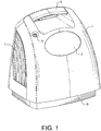
- Outer shell 1 includes carrying handle 3, oxygen product outlet 5 for insertion of a cannula to deliver oxygen product to the patient, air inlet grille 7 on one side of the shell, and support base or bottom platform 9 adapted to support the concentrator on a floor or any other surface.
- Shell 1 may be a single molded piece or may be formed by two or more shell sub-components joined to form the shell.
- a gas outlet grille (not seen in this view) is located on the other side of the shell.
- User interface panel 2 provides buttons and/or knobs which the patient can use to turn the unit on and off, switch between continuous product flow and conserver operation, and adjust the flow rate of the product.
- the interface panel may provide a display of icons and/or lights to indicate operational status and alarms for the concentrator, and also allow user selection of operating mode and product flow rates.
- a printed circuit board that controls the interface display may be located on the inside of the shell behind interface panel 2.
- Fig. 2 shows an external rear view of the concentrator with handle 3, air inlet grille 7, and support base 9 as shown in Fig. 1 .
- Two battery packs 11 and 13 are detachably connected to the rear external wall of the shell and contain rechargeable batteries that provide power to operate the concentrator.
- the battery packs are advantageously mounted outside the shell to reduce the generated heat load within the shell as described later.
- the concentrator shown in Figs. 1 and 2 typically weighs between about 3,6 kg (8 lb) and about 7,3 kg (16 lb). In one representative embodiment, the overall dimensions are approximately 330,2 mm (13 inches) high by 304,8 mm (12 inches) wide by 218,4 mm (8.6 inches) deep.
- FIG. 3 An exploded perspective view of the concentrator is given in Fig. 3 showing shell 1, interface panel 2, handle 3, air inlet grille 7,and battery packs 11 and 13 as shown in Figs. 1 and 2 . Also shown in Fig. 3 is outlet grille 8 and components of support base 9, namely, vertical wall segment 9a and horizontal lip 9b. Wall segment 9a is attached to a flat bottom portion (not visible) having a bottom surface adapted to rest on a floor or other external surface.
- Air separation system 15 which in this embodiment is a pressure swing adsorption system, is mounted on the upper surface of the flat bottom portion of support base 9.
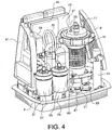
- FIG. 4 A larger view of the pressure swing adsorption system is shown in Fig. 4 and illustrates the general spatial relationship among some of the system components.
- Compressed air feed for the pressure swing adsorption system is provided by compressor or feed pump 17, which in this embodiment is a scroll compressor or pump driven by electric motor 19.
- Vacuum for operation of the pressure swing adsorption system is provided by vacuum compressor or pump 21, which in this embodiment is a scroll compressor or pump, is driven by motor 19, and is located coaxially with the motor and with compressor 17.
- the integrated pump assembly comprising compressor 17, motor 19, and vacuum pump 21 is attached to the flat bottom portion of support base 9 by a plurality of shock-absorbing flexible mounts, one of which is seen as flexible mount 23. While feed pump 17 and vacuum pump 21 in this embodiment are scroll-type pumps, any type of pump or compressor known in the art may be used.
- the pressure swing adsorption system uses four adsorbent columns, two of which are seen as adsorbent columns 25 and 27 that are removably mounted in cylindrical collars 29 and 31, respectively, which are part of a base assembly described later.
- adsorbent column 27 Immediately behind adsorbent column 27 is an empty column having similar dimensions that is utilized for product gas storage as later described.
- adsorbent column 25 and next to the product gas storage column is the rotary valve that directs gas flow to, from, and between the multiple adsorbent columns. Two additional adsorbent columns (not visible) are located behind the gas storage column and the rotary valve.
- the compressed gas outlet 33 of feed pump 17 is connected to cooling coil 35 for removing the heat of compression from the compressed air feed.
- Air inlet 37 is connected by tubing (not shown) to draw external air from an opening (not shown) inset into support bracket 41, wherein the opening draws ambient air through an open cell foam filter (not shown) behind air inlet grille 7 and then through a finer filter (e.g., felt or HEPA) before the compressor intake.
- a finer filter e.g., felt or HEPA
- a thin wall may be located between the base assembly and the integrated assembly of compressor 17, motor 19, and vacuum pump 21.
- the wall may be attached to the support base 9 and extend most or all of the way from front to back of base 9 and upward to at least the top of adsorbent column 25 and the adsorbent column behind the rotary valve. The purpose of the wall is to reduce the flow of warm air from the area around compressor 17, motor 19, and pump 21 which otherwise would flow back to the base assembly and adsorbent columns.
- Control modules 43 and 45 contain electronic control systems for AC/DC power conversion, controlling pump speed and rotary valve speed, monitoring product pressure, controlling conserver operation, controlling the display panel and providing system alarms, and managing charging of the batteries.
- the control modules contain printed circuit boards having a smart charging circuit to control battery charging when the concentrator is operating on external AC power.
- the charging circuit determines the amount of incoming power and the fraction of the incoming power that is being consumed by the concentrator. Any excess power is used the charge the batteries. The slower the concentrator is running, the more power is used to charge the batteries, which shortens the charging time.
- a look-up table in a controller in control module 43 or 45 sets the pump speed, rotary valve speed, and the flow control valve position.
- the goal is to maintain a constant operating pressure envelope (i.e., the range of maximum to minimum pressure over the course of the PSA cycle in the adsorbent beds) for the process.
- An optional feedback control loop may be used to monitor the product tank pressure and adjust the pump and rotary valve speed to maintain a constant average product tank pressure.
- Inlet 47 of vacuum pump 21 is connected via vacuum inlet line 49 to the feed stator of the rotary valve (not visible) to withdraw waste gas sequentially from each adsorbent column during the evacuation and purge steps in the adsorption cycle.
- the discharge of the vacuum pump passes through silencer or muffler 51 and is finally discharged through grille 8.
- the base assembly with the adsorbent columns, the gas storage column, and the rotary valve is shown in Fig. 5 after removal from support base 9 of Fig. 4 .
- the base assembly comprises a molded platform having bottom member 52 with a number of attached collars and brackets for mounting the adsorbent columns, the gas storage column, and the rotary valve.
- the base assembly has six attachment locations oriented symmetrically in two rows of three to form a "six-pack" configuration as shown.
- Five cylindrical collars are attached to the upper surface of the bottom member 52 and are adapted to detachably receive and support the respective ends of four cylindrical adsorbent columns and one empty column for product gas storage.
- the rotary valve is located between two of the adsorbent columns and directly adjacent all four of the adsorbent columns.
- Adsorbent column 27 is detachably mounted in and detachably connected to collar 31
- adsorbent column 25 is detachably mounted in and detachably connected to collar 29
- adsorbent column 53 is detachably mounted in and detachably connected to collar 55
- adsorbent column 61 is detachably mounted in and detachably connected to a fourth collar (not visible).
- Column 63 which is used for product gas storage and may be empty (i.e., contains none of the adsorbent for air separation located in the adsorbent columns), is detachably mounted in and detachably connected to a fifth collar (not visible).
- column 63 (the product gas storage tank) may be elongated to increase its volume and/or it may contain a different adsorbent material than the adsorbent material in the adsorbent columns, wherein the different adsorbent material is adapted to increase the effective product tank storage capacity by adsorbing product gas.
- Rotary valve 65 is mounted to bottom member 52 by four bolted mounts, two of which are seen here as mounts 67 and 69.
- the feed ends of the adsorbent columns are connected to the feed stator of rotary valve 65 by molded tubes 71, 73, 75, and 77.
- Outlet 79 of empty column 63 (the product gas storage column) is connected by a tube (not shown) to the built-in conserver (not shown), from which the product gas is supplied via oxygen product outlet 5 ( Fig. 1 ) to the patient's cannula.
- a bacterial filter (not shown) may be located between outlet 79 and oxygen product outlet 5.
- the conserver may be mounted on control modules 43 or 45, or alternatively on the printed circuit board behind interface panel 2. If the conserver is not used, continuous product gas flows from outlet 79 to oxygen product outlet 5.
- An optional external humidifier (not shown) may be mounted on the concentrator shell wherein the humidifier is adapted to humidify oxygen product gas from outlet 79 and deliver humidified gas to oxygen product outlet 5.
- Product purity typically is between 85 vol% and 96 vol% oxygen
- product gas flow rate is typically in the range of 0.25 to 3.5 LPM
- the delivery pressure is between 134 kPa (5 psig) and 162 kPa (9 psig).
- the adsorbent columns contain adsorbent material suitable for preferentially adsorbing nitrogen from air to yield an oxygen product containing at least 85 vol% oxygen.
- the adsorbent may be any of the commercially-available adsorbents for this service such as, for example, type X zeolite or low silica type X zeolite, wherein at least 80% of the cation sites are exchanged with lithium cations.
- each adsorbent column may contain one or more layers of different adsorbents for removing the water and carbon dioxide present in ambient air and may be selected from activated alumina and/or sodium type X zeolite or sodium/potassium low silica type X zeolite and/or various cation forms of chabazite.
- the adsorbent may be densely packed by various methods known in the art, such as snow fall loading and/or vibrated settling to prevent movement after loading.
- Each of these adsorbents may contain binder or be of a binderless composition, both of which can be manufactured by techniques known in the art.
- the shape of the adsorbent particles may be spherical, cylindrical, granular, or any structured adsorbent, such as laminates or monoliths.
- the adsorbent may be held in place by two flat circular diffusers at the feed and product ends of the adsorbent columns, wherein one of the diffusers is held under pressure by a spring, such as a wave spring.
- the circular diffuser may have a screen or mesh attached to the side adjacent to the adsorbent in order to prevent adsorbent from leaking through the openings in the diffuser.
- FIG. 6 A partially-exploded view of the base assembly is shown in Fig. 6 to illustrate the placement of the adsorbent columns and the rotary valve.
- Drive motor 81 and outer case 83 of the rotary valve are shown here separated from product rotor 85 and product stator 87, which is mounted directly on bottom member 52.
- the feed rotor and the feed stator are located within outer case 83.
- the feed ends of the adsorbent columns are connected to the inlets of the feed stator of the rotary valve by molded tubes 71, 73, 75, and 77.
- Vacuum outlet 105 connects the feed stator to vacuum pump 21 ( Fig. 4 ) by molded tube 49 (not shown in Fig. 6 ).
- the adsorbent columns and the product gas storage column are detachably mounted in and detachably connected to the collars that are attached to the upper surface of bottom member 52.
- Each column has a plurality of studs or bosses on the outer surface near the bottom that are adapted to be twisted for engagement and disengagement in notches formed in the sleeves.
- Adsorbent column 25 for example, has bosses 89 and 91 that snap into retaining notches 93 and 97, respectively, in collar 29.
- a third boss (not visible) engages and disengages from retaining notch 99 in collar 29.
- a view of an engaged boss and retaining notch is seen for adsorbent column 53, which is mounted in collar 55 by the engagement of boss 101 into retaining notch 103.
- Boss 101 can be disengaged from retaining notch 103 by rotating adsorbent column 53 counterclockwise (for example, by approximately 17 degrees) and lifting it vertically. The engagement of boss 101 with retaining notch 103 is effected by reversing these steps.
- This type of engaging and disengaging locking system is described here for illustration purposes only; other types of locking systems are possible and may be used to detachably mount the columns in the base assembly.
- Fig. 7 shows the base assembly without the columns and rotary valve to illustrate the construction of the assembly.
- the three collars 29, 31, and 55 were described in Figs. 4-7 ; the other collars not previously described are collars 107 and 109. All collars are connected directly to bottom member 52 wherein the collars and the bottom member may be fabricated separately and joined by an adhesive or welding. Alternatively, the collars and bottom member may be fabricated as a single piece. The combined collars and bottom member may be described as a molded platform. In one embodiment, the collars and bottom member are made of a plastic or polymeric material. The three retaining notches in each collar are all clearly visible.
- Mounts 67, 69, 111, and 113 are adapted for mounting rotary valve 65, typically by bolts (not shown) passing through the center of the mounts and engaging nuts located at the bottom of base 137.
- each of the collars is a centrally-located port in bottom member 52, three of which can be seen as column product ports 115 and 117 within collars 55 and 31, respectively, and as product gas storage column inlet port 119 within collar 107.
- Identical centrally-located column product ports are located within collars 29 and 109.
- Product stator 87 has centrally-located stator port 121 (also described as a product gas outlet port) and peripheral stator ports 123, 125, 127, and 129. These ports are adjacent the upper surface of bottom member 52 and may extend into bottom member 52.
- passages may be built into bottom member 52 to connect stator port 121 with gas storage column inlet port 119 and also to connect peripheral stator port 123 with column product port 117, peripheral stator port 125 with the column product port (not visible) within collar 29, peripheral stator port 127 with column product port 115, and peripheral stator port 129 with the column product port (not visible) within collar 109.
- Product stator 87 preferably is located adjacent all five collars so that none of the five passages within bottom member 52 cross and so that the five passages may be essentially co-planar.
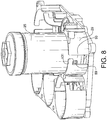
- Fig. 8 further illustrates the engaging and disengaging locking system of the embodiment shown in Figs. 3-6 .
- boss 89 on adsorbent column 25 is retained in retaining notch 93 by tab 131 that is formed in collar 29 by the specific shape of retaining notch 93.
- Adsorbent column 25 can be removed from collar 29 by rotating the column counterclockwise (for example, by approximately 17 degrees) and lifting the column vertically, thereby allowing boss 89 to pass through the open portion at the top of retaining notch 93. Installation is effected by reversing these steps.
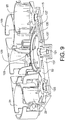
- the base assembly is further illustrated by the cross-sectional view of Fig. 9 , which is a section taken along an axis formed approximately by the centers of column product port 115, stator port 121 (also described as a product gas outlet port) of Fig. 7 , and column product port 133.
- the sectional view shows column product port 115 in collar 55, column product port 133 in collar 29, and stator port 121.
- Peripheral stator port 127 is connected and placed in flow communication with column product port 115 by passage 135.
- This passage may be formed as a channel within bottom member 52 wherein the channel is closed by joining the upper surface of base 137 to the lower surface of bottom member 52, thereby forming the passage.
- the channel could be formed in base 137.
- passage 135 may be formed by groups of partial channels, one group in base 137 and the other group as a mirror image in bottom member 52.
- bottom member 52 and base 137 may be defined as first and second sub-members that are joined at an interface as shown to form the bottom portion of the base assembly.
- Peripheral stator port 123 is connected and placed in flow communication with the column product port (not visible) within collar 31 by a passage (not visible) similar to passage 135.
- Peripheral stator port 129 is connected and placed in flow communication with the column product port (not visible) within collar 109 by a passage (not visible) similar to passage 135.
- Fig. 10 which is section 2-2 of Fig. 7 .
- the section shows column product ports 115, 117, 133, and 139; stator port 121; and peripheral stator ports 123, 125, 127, and 129.
- Passage 135 connects column product port 115 with peripheral stator port 127
- passage 141 connects column product port 139 with peripheral stator port 129
- passage 143 connects column product port 117 with peripheral stator port 123
- passage 145 connects column product port 133 with peripheral stator port 125.
- Passage 147 connects stator port 121 with product gas storage column inlet port 119.
- a one-way check valve may be installed in stator port 121 to ensure that oxygen product gas flows only in one direction from adsorbent columns 27, 53, 25, and 61, through the rotary valve, through passage 147, and into product gas storage column 63 via inlet port 119.
- the check valve can be installed in product gas storage column inlet port 119. The check valve thus is adapted to prevent backflow of oxygen product gas from product gas storage column 63 into the PSA system.
- passages 135, 141, 143, and 145 in Fig. 10 may be selected such that the dead volumes between the product end of each adsorbent column and the product end of the rotary valve are essentially equal in order to balance the operation of the columns during the adsorption cycle.
- lines 71, 73, 75, and 77 may be selected such that the dead volumes between the feed end of each adsorbent column and the feed end of the rotary valve are essentially equal in order to balance the operation of the columns during the adsorption cycle.
- Fig. 11 The interior regions of the adsorbent columns and rotary valve are shown in Fig. 11 , which is section 4-4 of Fig. 5 .
- Adsorbent column 25 is removably mounted in collar 29 as previously described.
- the bottom end of the column is fitted with tube 149 having compliant sealing element 151 (for example, an O-ring) located in a circumferential groove around the outer circumference of the tube.
- Tube 149 with compliant sealing element 151 is adapted to be sealably and removably inserted into column product port 133 located in bottom member 52 of the molded platform.
- adsorbent column 53 is removably mounted in collar 55 as previously described.
- the bottom end of the column is fitted with tube 153 having compliant sealing element 155, (for example, an O-ring) located in a circumferential groove around the outer circumference of the tube.
- Tube 153 with compliant sealing element 155 is adapted to be sealably and removably inserted into column product port 115 located in bottom member 52 of the molded platform.
- Adsorbent columns 27 and 61 likewise are sealably and removably inserted into column product ports 117 and 139, respectively (not visible).
- Column 63 which is used for product gas storage, similarly is fitted with a tube having a compliant sealing element, for example, an 0-ring, located in a circumferential groove around the outer circumference of the tube.
- the tube serves as a product gas inlet and has a compliant sealing element similar to compliant sealing element 155 that is adapted to be sealably and removably inserted into gas storage column inlet port 119 (not visible) located in bottom member 52 of the molded platform.
- any of the five columns (adsorbent columns 27, 53, 25, and 61 and gas product storage column 63) thus can be sealably and removably inserted into the appropriate gas storage column inlet ports located in bottom member 52 of the base assembly.
- the rotary valve used in this embodiment comprises two rotors and two stators, one rotor-stator set for directing gas flow at the feed ends of the adsorbent columns and the other for directing gas flow at the product ends of the adsorbent columns.
- the adsorbent columns described above are oriented such that the bottom ends are the product ends and the top ends are the feed ends.
- the function of the rotor-stator set serving the feed ends of the columns is to direct compressed air from the feed pump sequentially to each column for the feed/make product step of the process cycle and to connect each column sequentially with the vacuum pump to withdraw waste gas from each column during the purge and evacuation steps of the process cycle.
- the function of the rotor-stator set serving the product ends of the columns is to connect each adsorbent column sequentially with the inlet of the gas product storage tank during the feed/make product step of the cycle, to connect pairs of columns sequentially to allow gas transfer during the pressure equalization step, to connect pairs of columns sequentially to allow gas transfer during the purge/provide purge step, and to connect each column sequentially with the product gas outlet that leads to the product storage column during the product gas pressurization step.
- the valve shown in the sectional view of Fig. 11 uses the upper rotor-stator set for directing gas flow at the feed ends, i.e., the upper ends, of adsorbent columns 27, 53, 25, and 61.
- the lower rotor-stator set is used for directing gas flow between the product ends, i.e., the lower ends, of the adsorbent columns and between the adsorbent columns and gas product storage column 63.
- Upper or feed stator 159 has ports in flow communication with the upper or feed ends of adsorbent columns 27, 53, 25, and 61, a port in flow communication with the outlet of cooling coil 35 ( Fig. 4 ) connected to feed air compressor 17 ( Fig. 4 ), and a port in flow communication with vacuum outlet 105 ( Fig. 6 ) that connects to vacuum pump 21 ( Fig. 4 ).
- the ends of these ports are located in a flat, smooth face of upper or feed stator 159.
- Feed rotor 157 has a flat, smooth rotor face in sealable and rotatable contact with the face of feed stator 159 and has ports adapted to register sequentially with selected ports in the face of feed stator 159 as the face of feed rotor 157 rotates on the face of feed stator 159.
- Feed rotor 157 has internal passages that connect selected ports on the rotor face so that, as feed rotor 157 rotates, the feed ends of adsorbent columns 27, 25, 53, and 61 (or columns 61, 53, 25, and 27 if the rotors rotate in the opposite direction) are placed sequentially in selected flow communication with feed air compressor 17 and vacuum pump 21 according to the specific pressure swing adsorption cycle used in the process operation.
- Lower or product stator 161 has ports in flow communication with the lower or product ends of adsorbent columns 27, 53, 25, and 61, and a port in flow communication with the inlet of product gas storage column 63. The ends of these ports are located in a flat, smooth face of product stator 161.
- Product rotor 163 has a flat, smooth rotor face in sealable and rotatable contact with the face of product stator 161 and has ports adapted to register sequentially with selected ports in the face of product stator 161 as the face of product rotor 163 rotates on the face of product stator 161.
- Product rotor 163 has internal passages that connect selected ports on that stator face so that, as product rotor 163 rotates, the product ends of adsorbent columns 27, 25, 53, and 61 (or columns 61, 53, 25, and 27 if the rotors rotate in the opposite direction) are placed sequentially in selected flow communication with the inlet of product gas storage column 63 according to the specific pressure swing adsorption cycle used in the process operation.
- Product rotor 163 also has internal passages that connect pairs of selected ports on the rotor face so that, as product rotor 163rotates, the product ends of selected pairs of adsorbent columns are placed sequentially in flow communication according to the specific pressure swing adsorption cycle used in the process operation.
- the medical oxygen concentrator described above may be operated in any desired four-bed pressure swing adsorption (PSA) cycle.
- PSA pressure swing adsorption
- An exemplary schematic flowsheet is shown in Fig. 12 for a pressure/vacuum swing adsorption (PVSA) process using four adsorbent beds and a single product gas storage tank.
- PVSA pressure/vacuum swing adsorption
- ambient air via inlet line 165 is compressed to a pressure of 124 kPa (18 psia) to 179 kPa (26 psia) in feed pump 167 and flows via line 169 to the feed inlet of rotary valve 171.
- Feed pump 167 may be any type of gas compressor known in the art; in this embodiment, the pump is a scroll-type compressor or pump that is part of integrated pump system 173 comprising central drive motor 175, feed pump 167, and vacuum pump 177 (these may correspond, for example, to drive motor 19, feed pump 17, and vacuum pump 21 of Fig. 4 ).
- Rotary valve 171 comprises feed stator 159, feed rotor 157, product stator 161, and product rotor 163.
- Rotors 157 and 163 are rotated by a drive motor (not shown) that corresponds to drive motor 81 of Figs. 6 and 11 .
- Feed stator 159 has four feed ports connected to lines 71, 73, 75, and 77 (see also Fig.6 ) which in turn are connected to adsorbent columns 27, 61, 53, and 25 (see also Fig. 6 ), respectively.
- Another port on feed stator 159 is connected via line 179to vacuum pump 177.
- Feed rotor 157 has a flat, smooth rotor face in sealable and rotatable contact with the face of feed stator 159 and has ports adapted to register sequentially with selected ports in the face of feed stator 159 as the face of feed rotor 157 rotates on the face of feed stator 159.
- Feed rotor 157 has internal passages that connect selected ports on the rotor face so that, as feed rotor 157 rotates, the feed ends of adsorbent columns 27, 25, 53, and 61 (or columns 61, 53, 25, and 27) are placed sequentially in selected flow communication with feed air compressor 167 and vacuum pump 177 according to the specific pressure swing adsorption cycle used in the process operation.
- the internal cavity of rotary valve 171 may be maintained at sub-atmospheric pressure to protect the product ends of the adsorbent columns from contamination by water in ambient air in the event of leakage across the stator-rotor interfaces.
- Product stator 161 has four product ports that are connected via lines 135, 141, 143, and 145 to adsorbent columns 53, 61, 27, and 25, respectively. These lines correspond to channels 135, 141, 143, and 145 in Fig. 10 .
- Product stator 161 also has a port that is connected via line 147to product gas storage column 63. Line 147 corresponds to passage 147 of Fig. 10 .
- Oxygen product line 181 leads directly to oxygen product outlet 5 or to an optional built-in conserver (not shown).
- An exemplary pressure swing adsorption process using the system of Fig. 12 utilizes an eight-step repeating cycle outlined below for a given adsorbent column:
- Product repressurization step (8) may be followed by a feed repressurization step wherein feed gas is introduced into the feed end of the bed for a period prior to the initiation of product withdrawal in feed I make product step (1).
- Table 1 4-Bed PVSA Cycle Chart Column Step Number 27 1 2 3 4 5 6 7 8 61 7 8 1 2 3 4 5 6 53 5 6 7 8 1 2 3 4 25 3 4 5 6 7 8 1 2
- Rotary valve 171 controls the directions of sequential gas flow as follows: feed gas flow to each column and product gas from each column in turn during steps 1 and 2; product gas flow from a column making product or the product gas storage cylinder 63 to each column during product repressurization step 8; repressurization gas flow in turn from column 27 to column 53, column 61 to 25, column 53 to column 27, and column 25 to column 61 during steps 3 and 7; provide purge gas flow in turn from column 27 to column 25, column 61 to column 27, column 53 to column 61, and column 25 to column 53 during steps 4 and 6; evacuation waste gas flow from each column in turn during step 5; and purge waste gas flow from each column in turn during step 6.
- the elapsed time for each step may be set at any desired duration; an exemplary elapsed time of 1.0 second may be selected for each step, thereby giving an exemplary total repeating cycle time of 8.0 seconds.
- the four adsorbent column system described above utilizes a "six-pack" orientation in which the base assembly of Fig. 7 supports the four adsorbent beds, the product gas storage column, and the rotary valve in two symmetrical rows of three positions
- other orientations are possible as long as the rotary valve is adjacent each of the adsorbent columns.
- a pentagonal orientation is possible in which the rotary valve is surrounded symmetrically by the four adsorbent columns and product storage column.
- the two parallel rows of three positions may be offset rather than directly opposite as in Fig.
- Fig. 7 could be modified to support two adsorbent columns, one product gas storage column, and the rotary valve in a "four-pack" configuration.
- the "six-pack" orientation of Fig. 5 may be used with three adsorbent columns and two product gas storage columns.
- a system having five adsorbent columns and one product gas storage column may be used wherein the adsorbent columns and product gas storage column are located in a hexagonal pattern around the rotary valve.
- a system with seven adsorbent columns and one product gas storage column may be designed such that the columns and rotary valve positions are oriented in three parallel rows of three (i.e., a "nine-pack") with the rotary valve in the center.
- Other alternative geometries, numbers of adsorbent columns, and numbers of product gas storage columns can be envisioned by a skilled designer of these systems. Any of these alternatives may utilize the embodiment of the invention described above wherein the columns are mounted in a base assembly having integral internal passages that connect the columns with the ports of the rotary valve.
- Support base or bottom platform 9 defines a planar surface, and the concentrator is adapted to operate when the planar surface is oriented horizontally or at any angle from a horizontal plane.
- base 9 Figs. 1 and 2
- the concentrator may be operated while resting on its front or back, for example, under the seat of an airplane, train, bus, or ferry.
- the concentrator may be operated in any of several power supply modes. In one mode, the concentrator is operated on AC power while connected to an AC power outlet, and the batteries are recharged as necessary during this operation. In another mode, the concentrator is operated on AC power while the batteries are detached for external charging or maintenance. In a third mode, the concentrator is operated on battery power alone. In a fourth mode, the concentrator is operated on DC power while connected to a DC power outlet in a car or other means of transportation or alternatively while connected to a DC storage battery during an AC power outage. When operating on externally-supplied DC power, the concentrator batteries may be attached to or detached from the concentrator.
Landscapes
- Chemical & Material Sciences (AREA)
- Engineering & Computer Science (AREA)
- Analytical Chemistry (AREA)
- General Chemical & Material Sciences (AREA)
- Oil, Petroleum & Natural Gas (AREA)
- Chemical Kinetics & Catalysis (AREA)
- Separation Of Gases By Adsorption (AREA)
- Oxygen, Ozone, And Oxides In General (AREA)
Claims (33)
- Concentrateur d'oxygène médical portable comprenant(a) un système de séparation d'air (15) adapté pour récupérer l'oxygène de l'air ;(b) une plateforme inférieure (9) et une coque (1) présentant une paroi extérieure, dans lequel la coque (1) est reliée de manière détachable à la plateforme inférieure (9), dans lequel la coque (1) et la plateforme inférieure (9) définissent un volume enfermé lorsque la coque (1) est reliée à la plateforme inférieure (9), et dans lequel le système de séparation d'air (15) est agencé dans le volume enfermé ; et(c) une ou plusieurs batteries rechargeables (11, 13) adaptées pour fournir de l'énergie pour entraîner le système de séparation d'air (15) ;(d) le système de séparation d'air (15) comprenantcaractérisé en ce que(1) deux ou plus colonnes d'adsorption cylindriques (25, 27, 53, 61), chaque colonne incluant une extrémité d'alimentation, une extrémité de produit et du matériau adsorbant pour effectuer la séparation du gaz par adsorption sélective ;(2) un ensemble de pompe comprenant une pompe d'alimentation (17) présentant une sortie d'air compressé (33) et une pompe à vide (21) présentant une entrée de gaz ;(3) une sortie de produit d'oxygène (5) ;(4) une valve (65) présentant une première pluralité d'orifices adaptés pour placer la sortie d'air compressé de la pompe d'alimentation (17) en communication de flux séquentiellement avec l'extrémité d'alimentation de chaque colonne d'adsorption et pour placer l'entrée de gaz de la pompe à vide (21) en communication de flux séquentiellement avec l'extrémité d'alimentation de chaque colonne d'adsorption et présentant une seconde pluralité d'orifices adaptés pour placer la sortie de produit d'oxygène en communication de flux séquentiellement avec l'extrémité de produit de chaque colonne d'adsorption et pour placer l'extrémité de produit de chaque colonne d'adsorption en communication de flux séquentiellement avec l'extrémité de produit d'une autre colonne d'adsorption ; et(5) un ensemble de base attaché à la plateforme inférieure (9) et adapté pour supporter les deux ou plus colonnes d'adsorption (25, 27, 53, 61) ;(6) dans lequel l'ensemble de base comprend une plateforme moulée comprenant un élément inférieur (52) présentant une première surface et une seconde surface généralement parallèle à la première surface,(e) l'une ou les plusieurs batteries rechargeables (11, 13) sont reliées de manière détachable à la paroi extérieure de la coque (1) ;(f) la valve (65) est une valve rotative ;(g) l'ensemble de base est adapté pour supporter la valve rotative (65) ; et(h) l'ensemble de base comprend(1) deux ou plus colliers cylindriques (29, 31, 55, 107, 109) attachés à la première surface de l'élément inférieur (52) et adaptés pour recevoir et supporter de manière détachable les extrémités de produit respectives des deux ou plus colonnes d'adsorption cylindriques (25, 27, 53, 61),(2) et une plaque de stator à orifices (87) attachée à la première surface de l'élément inférieur (52), dans lequel la plaque de stator à orifices (87) fait partie de la valve rotative (65) et inclut la seconde pluralité d'orifices adaptés pour placer la sortie de produit d'oxygène en communication de flux séquentiellement avec l'extrémité de produit de chaque colonne d'adsorption (25, 27, 53, 61) et pour placer l'extrémité de produit de chaque colonne d'adsorption (25, 27, 53, 61) en communication de flux séquentiellement avec l'extrémité de produit d'une autre colonne d'adsorption.
- Concentrateur d'oxygène médical portable selon la revendication 1, dans lequel la coque (1) est une seule pièce moulée ou est formée par deux ou plus sous-composants de coque joints.
- Concentrateur d'oxygène médical portable selon la revendication 1, dans lequel la pompe d'alimentation (17) et la pompe à vide (21) sont des compresseurs de type à volute, chacun étant entraîné par un moteur d'entraînement commun (81), et dans lequel le moteur d'entraînement est disposé coaxialement entre la pompe d'alimentation (17) et la pompe à vide (21).
- Concentrateur d'oxygène médical portable selon la revendication 1, dans lequel la coque (1) présente une grille d'entrée (7), une grille de sortie (8) et un ventilateur (39) disposés dans le volume enfermé et adaptés pour aspirer l'air ambiant dans le volume enfermé et évacuer l'air chauffé depuis le volume enfermé.
- Concentrateur d'oxygène médical portable selon la revendication 1, dans lequel la coque (1) présente une extrémité inférieure adjacente à la plateforme inférieure (9) et une extrémité supérieure en regard de l'extrémité inférieure, dans lequel le volume enfermé inclut une paroi de séparation disposée entre l'ensemble de base et l'ensemble de pompe, et dans lequel la paroi de séparation s'étend vers le haut depuis la plateforme inférieure (9) jusqu'à un point entre la plateforme inférieure et l'extrémité supérieure de la coque.
- Concentrateur d'oxygène médical portable selon la revendication 1, comprenant un conservateur présentant une entrée en communication de flux avec la sortie de produit d'oxygène (5) et une sortie adaptée pour fournir par intermittence de l'oxygène à un patient, dans lequel le conservateur est adapté pour fournir de l'oxygène pendant la période d'inhalation du patient et pour ne pas fournir d'oxygène pendant la période d'expiration du patient.
- Concentrateur d'oxygène médical portable selon la revendication 1, dans lequel l'ensemble de pompe est monté sur la plateforme inférieure.
- Concentrateur d'oxygène médical portable selon la revendication 7, comprenant un système de commande et un conservateur, dans lequel les batteries rechargeables (11, 13) sont adaptées pour fournir de l'énergie au système de commande et au conservateur.
- Concentrateur d'oxygène médical portable selon la revendication 7, dans lequel la plateforme inférieure (9) définit une surface plane et dans lequel le concentrateur est adapté pour fonctionner lorsque la surface planaire est orientée horizontalement ou selon tout angle par rapport à un plan horizontal.
- Concentrateur d'oxygène médical portable selon la revendication 7, comprenant une bobine de refroidissement (35) attachée à la sortie d'air compressé de la pompe d'alimentation (17) et adaptée pour refroidir de l'air compressé chaud provenant de la pompe d'alimentation (17), dans lequel le ventilateur (39) est adapté pour passer de l'air ambiant sur la bobine de refroidissement (35) et la pompe d'alimentation (17).
- Concentrateur d'oxygène médical portable selon la revendication 1, dans lequel le système de séparation d'air comprend un réservoir de stockage de produit d'oxygène (63) en communication de flux avec la sortie de produit d'oxygène (5) et en communication de flux séquentiellement avec la sortie de produit sur l'extrémité de produit de chaque colonne d'adsorption (25, 27, 53, 61).
- Concentrateur d'oxygène médical portable selon la revendication 11, dans lequel le réservoir de stockage de produit d'oxygène (63) est une colonne cylindrique, ne contient pas de matériau adsorbant et est monté sur l'ensemble de base.
- Concentrateur d'oxygène médical portable selon la revendication 11, dans lequel le réservoir de stockage de produit d'oxygène (63) contient un matériau adsorbant différent du matériau adsorbant dans les colonnes d'adsorption (25, 27, 53, 61), dans lequel le matériau adsorbant différent est adapté pour augmenter la capacité de stockage de réservoir de produit effective.
- Concentrateur d'oxygène médical portable selon la revendication 1, dans lequel la plaque de stator à orifices (87) présente un orifice de stator central (121) et deux ou plus orifices de stator périphériques (123, 125, 127, 129) adjacents à la première surface de l'élément inférieur ; dans lequel un orifice de produit de colonne (115, 117, 133, 139) est disposé dans l'élément inférieur de la plateforme moulée dans chacun des deux ou plus colliers cylindriques (29, 31, 55, 107, 109), chaque orifice de produit de colonne s'étendant depuis la première surface de l'élément inférieur jusqu'à un point entre la première surface et la seconde surface de l'élément inférieur ; dans lequel chaque orifice de produit de colonne (115, 117, 133, 139) et chaque colonne d'adsorption cylindrique (25, 27, 53, 61) sont adaptés de sorte que la sortie de produit d'une colonne d'adsorption cylindrique puisse être reliée de manière étanche et amovible à un orifice de produit de colonne ; et dans lequel chaque orifice de stator périphérique (123, 125, 127, 129) est relié à un orifice de produit de colonne respectif (115, 117, 133, 139) par un passage (135, 139, 143, 145) disposé dans l'élément inférieur de l'ensemble de base.
- Concentrateur d'oxygène médical portable selon la revendication 1, dans lequel les colonnes d'adsorption cylindriques (25, 27, 53, 61) et/ou l'ensemble de base comprend un matériau plastique ou polymère.
- Concentrateur d'oxygène médical portable selon la revendication 1, dans lequel l'élément inférieur (52) et les deux ou plus colliers cylindriques (29, 31, 55, 107, 109) sont formés à partir d'une seule pièce de matériau plastique ou polymère moulé.
- Concentrateur d'oxygène médical portable selon la revendication 14, comprenant un réservoir de stockage de produit d'oxygène (63) en communication de flux avec la sortie de produit d'oxygène et en communication de flux par le biais de l'orifice de stator central (121) avec la sortie de produit sur l'extrémité de produit de chaque colonne d'adsorption, dans lequel le réservoir de stockage de produit d'oxygène (63) est une des deux ou plus colonnes cylindriques, ne contient pas de matériau adsorbant et est supporté de manière détachable dans un des colliers cylindriques (29, 31, 55, 107, 109) sur l'ensemble de base; dans lequel l'entrée d'alimentation du réservoir de stockage de produit d'oxygène est adaptée pour être reliée de manière étanche et amovible à un orifice de produit de colonne (119) disposé dans l'élément inférieur (52) de la plateforme moulée dans le collier cylindrique ; et dans lequel l'orifice de produit de colonne (119) est relié à l'orifice de stator central par un passage (147) disposé dans l'élément inférieur de l'ensemble de base.
- Concentrateur d'oxygène médical portable selon la revendication 1, dans lequel la plaque de stator à orifices (87) présente un orifice de stator central (121) et deux ou plus orifices de stator périphériques (123, 125, 127, 129) adjacents à la première surface de l'élément inférieur ;
et dans lequel un orifice de produit de colonne (115, 117, 133, 139) est disposé dans l'élément inférieur (52) de la plateforme moulée dans chacun des deux ou plusieurs colliers cylindriques (29, 31, 55, 107, 109), chaque orifice de produit de colonne s'étendant depuis la première surface de l'élément inférieur (52) jusqu'à un point entre la première surface et la seconde surface de l'élément inférieur, chaque orifice de produit de colonne (115, 117, 133, 139) étant adapté pour être relié de manière étanche et amovible à une colonne cylindrique, et dans lequel chaque orifice de stator périphérique (123, 125, 127, 129) est relié à un orifice de produit de colonne respectif par un passage (135, 139, 143, 145) disposé dans l'élément inférieur de l'ensemble de base. - Concentrateur d'oxygène médical portable selon la revendication 18, dans lequel l'ensemble de base comprend les deux ou plus colonnes d'adsorption cylindriques, chaque colonne présentant un intérieur et un tube sur une extrémité en communication de flux avec l'intérieur, dans lequel le tube présente un élément étanche élastique disposé autour d'une circonférence extérieure de celui-ci, et dans lequel le tube avec l'élément étanche élastique est adapté pour être inséré de manière étanche et amovible dans un orifice de produit de colonne (115, 117, 133, 139) disposé dans l'élément inférieur (52) de la plateforme moulée.
- Concentrateur d'oxygène médical portable selon la revendication 19, dans lequel l'élément étanche élastique est un joint torique disposé dans une rainure circonférentielle dans une surface extérieure du tube et dans lequel le joint torique est dimensionné de sorte que le tube et le joint torique puissent être insérés de manière étanche et amovible dans un orifice de produit de colonne (115, 117, 133, 139).
- Concentrateur d'oxygène médical portable selon la revendication 20, dans lequel chaque colonne (25, 27, 53, 61) est adaptée pour être verrouillée dans un collier cylindrique (29, 31, 55, 107, 109) alors que le tube et le joint torique sont insérés de manière étanche dans l'orifice de produit de colonne (115, 117, 133, 139) du collier cylindrique et est adaptée pour être déverrouillée du collier cylindrique alors que le tube et le joint torique sont retirés de l'orifice de produit de colonne.
- Concentrateur d'oxygène médical portable selon la revendication 18, dans lequel au moins deux des deux ou plus colonnes cylindriques sont des colonnes d'adsorption (25, 27, 53, 61) contenant du matériau adsorbant pour effectuer la séparation du gaz par adsorption sélective.
- Concentrateur d'oxygène médical portable selon la revendication 18, dans lequel au moins une des deux ou plus colonnes cylindriques est adaptée pour être utilisée comme un réservoir de stockage de produit d'oxygène (63).
- Concentrateur d'oxygène médical portable selon la revendication 23, dans lequel le réservoir de stockage de produit d'oxygène (63) contient un matériau adsorbant adapté pour augmenter la capacité de stockage de réservoir de produit effective.
- Concentrateur d'oxygène médical portable selon la revendication 18, dans lequel l'élément inférieur (52) comprend(1) un premier sous-élément incluant la première surface, les deux ou plus colliers cylindriques (29, 31, 55, 107, 109) attachés à la première surface, une première surface intermédiaire généralement parallèle à la première surface, et des canaux ouverts qui forment des parties des passages (135, 141, 143, 145) reliant chaque orifice de stator périphérique (123, 125, 127, 129) à un orifice de produit de colonne respectif (115, 117, 133, 139) ; et(2) un second sous-élément incluant la seconde surface et une seconde surface intermédiaire généralement parallèle à la seconde surface ;dans lequel les première et seconde surfaces intermédiaires sont jointes de sorte que les premiers canaux ouverts dans le premier sous-ensemble soient couverts par la seconde surface intermédiaire, formant par là même les passages disposés dans l'élément inférieur de l'ensemble de base qui relient chaque orifice de stator périphérique (123, 125, 127, 129) à un orifice de produit de colonne respectif (115, 117, 133, 139).
- Concentrateur d'oxygène médical portable selon la revendication 18, dans lequel l'élément inférieur (52) comprend(1) un premier sous-élément incluant la première surface, les deux ou plus colliers cylindriques (29, 31, 55, 107, 109) attachés à la première surface, une première surface intermédiaire généralement parallèle à la première surface, et des premiers canaux ouverts qui forment des premières parties des passages (135, 141, 143, 145) reliant chaque orifice de stator périphérique (123, 125, 127, 129) à un orifice de produit de colonne respectif (115, 117, 133, 139) ; et(2) un second sous-élément incluant la seconde surface, une seconde surface intermédiaire généralement parallèle à la seconde surface, et des seconds canaux ouverts qui forment des secondes parties des passages (135, 141, 143, 145) reliant chaque orifice de stator périphérique à un orifice de produit de colonne respectif ; dans lequel les première et seconde surfaces intermédiaires sont jointes de sorte que les premiers canaux ouverts dans le premier sous-ensemble soient concordants avec les seconds canaux ouverts du second sous-élément, formant par là même les passages (135, 141, 143, 145) disposés dans l'élément inférieur (52) de l'ensemble de base qui relient chaque orifice de stator périphérique (123, 125, 127, 129) à un orifice de produit de colonne respectif (115, 117, 133, 139).
- Concentrateur d'oxygène médical portable selon la revendication 18, dans lequel l'un quelconque de la plateforme moulée, des deux ou plus colliers cylindriques (29, 31, 55, 107, 109) et des deux ou plus colonnes d'adsorption cylindriques (25, 27, 53, 61) comprend du matériau plastique ou polymère.
- Concentrateur d'oxygène médical portable selon la revendication 1, dans lequel le système de séparation d'air (15) inclut
quatre ou plus colonnes cylindriques (25, 27, 53, 61, 63), dans lequel chaque colonne inclut une extrémité d'alimentation, une entrée d'alimentation sur l'extrémité d'alimentation, une extrémité de produit et une sortie de produit sur l'extrémité de produit, et dans lequel au moins quatre des colonnes cylindriques sont des colonnes d'adsorption (25, 27, 53, 61) contenant du matériau adsorbant pour effectuer la séparation d'air par l'adsorption sélective ;
la première pluralité d'orifices adaptée pour placer la sortie d'air compressé de la pompe d'alimentation en communication de flux séquentiellement avec l'extrémité d'alimentation de chaque colonne d'adsorption et pour placer l'entrée de gaz de la pompe à vide en communication de flux séquentiellement avec l'extrémité d'alimentation de chaque colonne d'adsorption, et la seconde pluralité d'orifices adaptée pour placer l'orifice de sortie de gaz de produit en communication de flux séquentiellement avec l'extrémité de produit de chaque colonne d'adsorption et pour placer l'extrémité de produit de chaque colonne d'adsorption en communication de flux séquentiellement avec l'extrémité de produit d'une autre colonne d'adsorption ; la valve rotative présentant un orifice de sortie de gaz de produit ; et
l'ensemble de base adapté pour supporter les au moins quatre colonnes d'adsorption et la valve rotative ;
dans lequel l'une ou plusieurs batteries rechargeables sont adaptées pour fournir de l'énergie pour entraîner la pompe d'alimentation (17), la pompe à vide (21) et la valve rotative (65). - Concentrateur d'oxygène médical portable selon la revendication 28, comprenant un réservoir de stockage de produit d'oxygène (63) en communication de flux continu avec l'orifice de sortie de gaz de produit et en communication de flux séquentiel avec la sortie de produit sur l'extrémité de produit de chaque colonne d'adsorption (25, 27, 53, 61).
- Concentrateur d'oxygène médical portable selon la revendication 29, comprenant un clapet antiretour présentant une entrée et une sortie, des tuyaux reliant l'orifice de sortie de gaz de produit à l'entrée du clapet antiretour, et des tuyaux reliant la sortie du clapet antiretour au réservoir de stockage de produit d'oxygène (63).
- Concentrateur d'oxygène médical portable selon la revendication 29, dans lequel le réservoir de stockage de produit d'oxygène (63) est une des colonnes cylindriques et est monté sur l'ensemble de base.
- Concentrateur d'oxygène médical portable selon la revendication 31, dans lequel le réservoir de stockage de produit d'oxygène (63) contient un matériau adsorbant différent du matériau adsorbant dans les colonnes d'adsorption, dans lequel le matériau adsorbant différent est adapté pour augmenter la capacité effective de stockage de réservoir de produit.
- Concentrateur d'oxygène médical portable selon la revendication 31, comprenant un conservateur adapté pour fournir du produit d'oxygène provenant du réservoir de stockage de produit d'oxygène (63) à la sortie de produit d'oxygène (5), dans lequel le conservateur est adapté pour fournir l'oxygène pendant une période d'inhalation du patient et pour ne pas fournir d'oxygène pendant la période d'expiration du patient.
Priority Applications (1)
| Application Number | Priority Date | Filing Date | Title |
|---|---|---|---|
| EP10190289.8A EP2316517B1 (fr) | 2005-12-20 | 2006-12-14 | Ensemble base pour un concentrateur d'oxygène médical portable |
Applications Claiming Priority (1)
| Application Number | Priority Date | Filing Date | Title |
|---|---|---|---|
| US11/312,180 US7510601B2 (en) | 2005-12-20 | 2005-12-20 | Portable medical oxygen concentrator |
Related Child Applications (3)
| Application Number | Title | Priority Date | Filing Date |
|---|---|---|---|
| EP10190289.8A Division-Into EP2316517B1 (fr) | 2005-12-20 | 2006-12-14 | Ensemble base pour un concentrateur d'oxygène médical portable |
| EP10190289.8A Division EP2316517B1 (fr) | 2005-12-20 | 2006-12-14 | Ensemble base pour un concentrateur d'oxygène médical portable |
| EP10190289.8A Previously-Filed-Application EP2316517B1 (fr) | 2005-12-20 | 2006-12-14 | Ensemble base pour un concentrateur d'oxygène médical portable |
Publications (3)
| Publication Number | Publication Date |
|---|---|
| EP1800731A2 EP1800731A2 (fr) | 2007-06-27 |
| EP1800731A3 EP1800731A3 (fr) | 2008-07-30 |
| EP1800731B1 true EP1800731B1 (fr) | 2017-05-24 |
Family
ID=37908299
Family Applications (2)
| Application Number | Title | Priority Date | Filing Date |
|---|---|---|---|
| EP06025927.2A Active EP1800731B1 (fr) | 2005-12-20 | 2006-12-14 | Concentrateur d'oxygène médical portable |
| EP10190289.8A Active EP2316517B1 (fr) | 2005-12-20 | 2006-12-14 | Ensemble base pour un concentrateur d'oxygène médical portable |
Family Applications After (1)
| Application Number | Title | Priority Date | Filing Date |
|---|---|---|---|
| EP10190289.8A Active EP2316517B1 (fr) | 2005-12-20 | 2006-12-14 | Ensemble base pour un concentrateur d'oxygène médical portable |
Country Status (4)
| Country | Link |
|---|---|
| US (1) | US7510601B2 (fr) |
| EP (2) | EP1800731B1 (fr) |
| JP (1) | JP4495140B2 (fr) |
| ES (2) | ES2628000T3 (fr) |
Families Citing this family (112)
| Publication number | Priority date | Publication date | Assignee | Title |
|---|---|---|---|---|
| US7954490B2 (en) | 2005-02-09 | 2011-06-07 | Vbox, Incorporated | Method of providing ambulatory oxygen |
| US7588612B2 (en) * | 2005-07-19 | 2009-09-15 | Bank Of America, N.A. | Mobile nitrogen generation device |
| WO2008004523A1 (fr) * | 2006-07-03 | 2008-01-10 | Sanyo Electronic Industries Co., Ltd. | dispositif DE CONCENTRATION D'OXYGÈNE |
| CA2668055A1 (fr) * | 2006-11-01 | 2008-05-08 | Joseph Fisher | Dispositif de survie portable |
| JP3139801U (ja) * | 2006-12-31 | 2008-02-28 | 冬雷 王 | 携帯型psa式酸素発生器 |
| US8187367B2 (en) * | 2006-12-31 | 2012-05-29 | Wang Dong-Lei | Portable PSA oxygen generator |
| US20080302516A1 (en) * | 2007-06-08 | 2008-12-11 | Sequal Technologies, Inc. | Compressor Cooling System and Method of Use |
| US20090065007A1 (en) | 2007-09-06 | 2009-03-12 | Wilkinson William R | Oxygen concentrator apparatus and method |
| US20090205494A1 (en) * | 2008-02-20 | 2009-08-20 | Mcclain Michael S | Single manifold assembly for oxygen-generating systems |
| US20110214673A1 (en) * | 2008-05-08 | 2011-09-08 | Edward Masionis | Portable Life Support Apparatus Ventilator |
| USD606655S1 (en) | 2008-06-27 | 2009-12-22 | Inova Labs, Llc | Portable oxygen concentrator |
| TWI404674B (zh) * | 2008-09-25 | 2013-08-11 | Yunn Tong Electronic Entpr Co Ltd | oxygen machine |
| TWI404673B (zh) * | 2008-09-25 | 2013-08-11 | Yunn Tong Electronic Entpr Co Ltd | Multi - channel mobile oxygen machine |
| US8236095B1 (en) | 2008-10-17 | 2012-08-07 | O2 Concepts, LLC | Vacuum-pressure swing absorption concentrator |
| JP5430129B2 (ja) * | 2008-11-21 | 2014-02-26 | フクダ電子株式会社 | 酸素濃縮器 |
| US8695600B2 (en) * | 2009-07-22 | 2014-04-15 | Vbox, Incorporated | Method of separating and distributing oxygen |
| US8894751B2 (en) | 2009-10-05 | 2014-11-25 | Separation Design Group Llc | Ultra rapid cycle portable oxygen concentrator |
| US20250339637A9 (en) * | 2009-10-05 | 2025-11-06 | Separation Design Group Ip Holdings, Llc | Ultra rapid cycle portable oxygen concentrator |
| USD666724S1 (en) * | 2009-10-14 | 2012-09-04 | Drager Safety Ag & Co. Kgaa | Oxygen self rescuer |
| JP5495766B2 (ja) * | 2009-12-18 | 2014-05-21 | 株式会社医器研 | 酸素濃縮装置 |
| NZ601654A (en) * | 2010-02-09 | 2014-09-26 | Invacare Corp | Breathing gas supply system |
| US8517729B2 (en) * | 2010-03-04 | 2013-08-27 | The University of Western Ontario and Trudell Medical International | Oral mouthpiece and method for the use thereof |
| US9974920B2 (en) | 2010-04-07 | 2018-05-22 | Caire Inc. | Portable oxygen delivery device |
| US8616207B2 (en) | 2010-09-07 | 2013-12-31 | Inova Labs, Inc. | Oxygen concentrator heat management system and method |
| US20120055474A1 (en) | 2010-09-07 | 2012-03-08 | Wilkinson William R | Methods and systems for providing oxygen enriched gas |
| US8440004B2 (en) * | 2010-12-30 | 2013-05-14 | Inogen, Inc. | Advanced portable oxygen concentrator |
| CA2842928A1 (fr) | 2011-03-01 | 2012-11-29 | Exxonmobil Upstream Research Company | Appareil et systemes ayant un ensemble robinet rotatif et procedes d'adsorption modulee s'y rapportant |
| BR112013018597A2 (pt) | 2011-03-01 | 2019-01-08 | Exxonmobil Upstream Res Co | aparelho e sistemas tendo um contator adsorvente encaixado e processos de adsorção oscilante |
| JP2012200387A (ja) * | 2011-03-25 | 2012-10-22 | Fujikura Rubber Ltd | 酸素濃縮装置用酸素タンクユニット |
| US10695520B2 (en) | 2011-04-22 | 2020-06-30 | Inogen, Inc. | Gas concentrator with removable cartridge adsorbent beds |
| US9592360B2 (en) | 2011-04-22 | 2017-03-14 | Inogen, Inc. | Gas concentrator with removable cartridge adsorbent beds |
| WO2013038286A1 (fr) | 2011-09-13 | 2013-03-21 | Koninklijke Philips Electronics N.V. | Recharge de batterie utilisant des références croisées avec les applications concernées pour la limitation dynamique du courant |
| WO2013043210A1 (fr) * | 2011-11-03 | 2013-03-28 | Draeger Medical Systems, Inc. | Compresseur d'air de qualité médicale, transportable |
| AU2013328912B2 (en) | 2012-10-12 | 2017-10-12 | Inova Labs, Inc. | Method and systems for the delivery of oxygen enriched gas |
| JP6336991B2 (ja) | 2012-10-12 | 2018-06-06 | イノヴァ ラボ,インコーポレイテッド | 酸素濃縮器二重化システムおよび方法 |
| NZ707260A (en) | 2012-10-12 | 2017-12-22 | Inova Labs Inc | Oxygen concentrator systems and methods |
| JP6162961B2 (ja) * | 2013-01-18 | 2017-07-12 | フクダ電子株式会社 | 流量制御ユニット及びこれを備える酸素濃縮器 |
| JP6247442B2 (ja) * | 2013-01-18 | 2017-12-13 | フクダ電子株式会社 | 継手構造及び酸素濃縮器 |
| CN104968410B (zh) | 2013-01-30 | 2019-06-04 | 皇家飞利浦有限公司 | 氧气分离系统及生成富氧气体的流的方法 |
| US9061238B2 (en) * | 2013-03-15 | 2015-06-23 | Invacare Corporation | Gas concentrator |
| CN105765220B (zh) * | 2013-10-09 | 2020-03-27 | 查特股份有限公司 | 具有自旋行星式几何结构的自旋泵 |
| US10004869B2 (en) | 2013-12-27 | 2018-06-26 | Inogen, Inc. | Gas concentrator with removable cartridge adsorbent beds |
| US9440179B2 (en) | 2014-02-14 | 2016-09-13 | InovaLabs, LLC | Oxygen concentrator pump systems and methods |
| US20150238721A1 (en) * | 2014-02-24 | 2015-08-27 | Vetland Medical Sales and Services, LLC | Electronic E-Cylinder |
| US9675925B2 (en) | 2014-07-25 | 2017-06-13 | Exxonmobil Upstream Research Company | Apparatus and system having a valve assembly and swing adsorption processes related thereto |
| RU2699551C2 (ru) | 2014-11-11 | 2019-09-06 | Эксонмобил Апстрим Рисерч Компани | Высокоемкие структуры и монолиты посредством печати пасты |
| AU2015361102B2 (en) | 2014-12-10 | 2018-09-13 | Exxonmobil Research And Engineering Company | Adsorbent-incorporated polymer fibers in packed bed and fabric contactors, and methods and devices using same |
| AU2015370106B2 (en) | 2014-12-23 | 2019-01-03 | Exxonmobil Upstream Research Company | Structured adsorbent beds, methods of producing the same and uses thereof |
| US10315002B2 (en) | 2015-03-24 | 2019-06-11 | Ventec Life Systems, Inc. | Ventilator with integrated oxygen production |
| US11247015B2 (en) | 2015-03-24 | 2022-02-15 | Ventec Life Systems, Inc. | Ventilator with integrated oxygen production |
| CA2979870C (fr) | 2015-05-15 | 2019-12-03 | Exxonmobil Upstream Research Company | Appareil et systeme pour procedes d'adsorption par oscillation associes a ceux-ci |
| US9861929B2 (en) | 2015-05-15 | 2018-01-09 | Exxonmobil Upstream Research Company | Apparatus and system for swing adsorption processes related thereto |
| US10293298B2 (en) | 2015-09-02 | 2019-05-21 | Exxonmobil Upstream Research Company | Apparatus and system for combined temperature and pressure swing adsorption processes related thereto |
| WO2017039991A1 (fr) | 2015-09-02 | 2017-03-09 | Exxonmobil Upstream Research Company | Procédé et système pour adsorption modulée au moyen d'un flux de tête d'un déméthaniseur comme gaz de purge |
| AU2016346798B2 (en) | 2015-10-27 | 2019-11-07 | Exxonmobil Upstream Research Company | Apparatus and system for swing adsorption processes related thereto having actively-controlled feed poppet valves and passively controlled product valves |
| KR102118860B1 (ko) | 2015-10-27 | 2020-06-04 | 엑손모빌 업스트림 리서치 캄파니 | 복수의 밸브들을 갖는 관련 스윙 흡착 공정을 위한 장치 및 시스템 |
| EP3368188A1 (fr) | 2015-10-27 | 2018-09-05 | Exxonmobil Upstream Research Company | Appareil et système pour procédés d'adsorption modulée correspondants comprenant plusieurs soupapes |
| KR20180083911A (ko) | 2015-11-16 | 2018-07-23 | 엑손모빌 업스트림 리서치 캄파니 | 흡착재 및 이산화탄소의 흡착 방법 |
| EP3429727B1 (fr) | 2016-03-18 | 2025-02-12 | ExxonMobil Technology and Engineering Company | Appareil et methode pour procédés d'adsorption modulée |
| WO2017192660A1 (fr) | 2016-05-03 | 2017-11-09 | Inova Labs, Inc. | Procédé et systèmes pour l'administration de gaz enrichi en oxygène |
| FR3051374B1 (fr) * | 2016-05-18 | 2018-05-18 | L'air Liquide, Societe Anonyme Pour L'etude Et L'exploitation Des Procedes Georges Claude | Procede de production d’oxygene de type vsa avec regeneration periodique |
| US10427089B2 (en) | 2016-05-31 | 2019-10-01 | Exxonmobil Upstream Research Company | Apparatus and system for swing adsorption processes |
| RU2716686C1 (ru) | 2016-05-31 | 2020-03-13 | Эксонмобил Апстрим Рисерч Компани | Устройство и система для осуществления процессов короткоцикловой адсорбции |
| US10773049B2 (en) | 2016-06-21 | 2020-09-15 | Ventec Life Systems, Inc. | Cough-assist systems with humidifier bypass |
| WO2018001933A1 (fr) * | 2016-06-29 | 2018-01-04 | Koninklijke Philips N.V. | Ensemble vanne rotative pour système d'adsorption par variation de pression |
| US10882003B2 (en) | 2016-06-29 | 2021-01-05 | Koninklijke Philips N.V. | Rotary valve assembly for sieve beds for pressure swing adsorption control |
| US10434458B2 (en) | 2016-08-31 | 2019-10-08 | Exxonmobil Upstream Research Company | Apparatus and system for swing adsorption processes related thereto |
| US10603626B2 (en) | 2016-09-01 | 2020-03-31 | Exxonmobil Upstream Research Company | Swing adsorption processes using zeolite structures |
| US10328382B2 (en) | 2016-09-29 | 2019-06-25 | Exxonmobil Upstream Research Company | Apparatus and system for testing swing adsorption processes |
| US10710053B2 (en) | 2016-12-21 | 2020-07-14 | Exxonmobil Upstream Research Company | Self-supporting structures having active materials |
| KR102260066B1 (ko) | 2016-12-21 | 2021-06-04 | 엑손모빌 업스트림 리서치 캄파니 | 발포형 기하구조 및 활물질을 갖는 자체-지지 구조물 |
| WO2018151958A1 (fr) * | 2017-02-14 | 2018-08-23 | Caire Inc. | Ensemble concentrateur d'oxygène portable extrudé |
| US10576235B2 (en) | 2017-05-18 | 2020-03-03 | Tokitae Llc | Management of a therapeutic oxygen delivery system |
| WO2018226532A1 (fr) * | 2017-06-06 | 2018-12-13 | Separation Design Group, Llc | Concentrateur d'oxygène configurable et procédé associé |
| EP3892356A1 (fr) * | 2017-06-22 | 2021-10-13 | Allied Healthcare Products, Inc. | Système d'absorption de dioxyde de carbone portable |
| WO2019147516A1 (fr) | 2018-01-24 | 2019-08-01 | Exxonmobil Upstream Research Company | Appareil et système d'adsorption à température modulée |
| WO2019168628A1 (fr) | 2018-02-28 | 2019-09-06 | Exxonmobil Upstream Research Company | Appareil et système pour procédés d'adsorption modulée |
| JP6466008B1 (ja) * | 2018-03-22 | 2019-02-06 | レール・リキード−ソシエテ・アノニム・プール・レテュード・エ・レクスプロワタシオン・デ・プロセデ・ジョルジュ・クロード | 吸着塔の切替装置 |
| EP4470589A3 (fr) | 2018-05-13 | 2025-02-19 | Ventec Life Systems, Inc. | Système portable de ventilateur médical utilisant des concentrateurs portables d'oxygène |
| USD861874S1 (en) * | 2018-05-15 | 2019-10-01 | Ngk Spark Plug Co., Ltd. | Medical oxygen concentrator |
| USD854691S1 (en) * | 2018-05-22 | 2019-07-23 | Ngk Spark Plug Co., Ltd. | Medical oxygen concentrator |
| US11260338B2 (en) | 2018-08-09 | 2022-03-01 | O2 Air-Sea, Llc | Oxygen generation device |
| JP7195887B2 (ja) * | 2018-11-19 | 2022-12-26 | 大陽日酸株式会社 | 圧力変動吸着装置 |
| US11318410B2 (en) | 2018-12-21 | 2022-05-03 | Exxonmobil Upstream Research Company | Flow modulation systems, apparatus, and methods for cyclical swing adsorption |
| CN113747965A (zh) | 2019-04-01 | 2021-12-03 | 艾诺格有限公司 | 紧凑型便携式氧气浓缩器 |
| WO2020222932A1 (fr) | 2019-04-30 | 2020-11-05 | Exxonmobil Upstream Research Company | Lit adsorbant à cycle rapide |
| US20220257895A1 (en) * | 2019-07-31 | 2022-08-18 | ResMed Asia Pte. Ltd. | Efficient vacuum pressure swing adsorption systems and methods |
| WO2021071755A1 (fr) | 2019-10-07 | 2021-04-15 | Exxonmobil Upstream Research Company | Procédés et systèmes d'adsorption utilisant une commande d'élévation de pas de soupapes champignon à actionnement hydraulique |
| US11433346B2 (en) | 2019-10-16 | 2022-09-06 | Exxonmobil Upstream Research Company | Dehydration processes utilizing cationic zeolite RHO |
| US20230012016A1 (en) * | 2019-11-27 | 2023-01-12 | ResMed Asia Pte. Ltd. | Oxygen tank with improved oxygen storage |
| CN115279441B (zh) * | 2020-03-27 | 2024-12-06 | 帝人制药株式会社 | 氧浓缩装置 |
| US12251519B2 (en) * | 2020-06-24 | 2025-03-18 | O2-Matic Products Private Limited | Portable oxygen generator system |
| CN111939405B (zh) * | 2020-08-13 | 2023-02-21 | 安徽康居人健康科技有限公司 | 一种便于拆卸的呼吸制氧一体机 |
| CA3198718A1 (fr) | 2020-11-06 | 2022-05-12 | Ventec Life Systems, Inc. | Systemes, dispositifs et procedes de gestion de donnees de therapie respiratoire |
| JP2024503250A (ja) | 2020-12-21 | 2024-01-25 | ベンテック ライフ システムズ, インコーポレイテッド | 一体化された酸素送達を有するベンチレータシステムおよび関連付けられたデバイスおよび方法 |
| WO2022160129A1 (fr) * | 2021-01-27 | 2022-08-04 | 南京壹诺吉医疗科技有限公司 | Générateur d'oxygène miniature |
| USD963836S1 (en) * | 2021-05-14 | 2022-09-13 | Shenzhen Nomei Jia Environmental Technology Co. Ltd. | Nebulizer |
| IT202100013601A1 (it) * | 2021-05-25 | 2022-11-25 | 77 Vision Way Ltd | Dispositivo di distillazione di acqua |
| USD1018858S1 (en) * | 2021-07-15 | 2024-03-19 | Ventec Life Systems, Inc. | Oxygen concentrator |
| JP1716179S (ja) * | 2021-09-13 | 2022-05-30 | 携帯用酸素発生器 | |
| CN113860260B (zh) * | 2021-10-25 | 2023-06-30 | 浙江和氧气体科技有限公司 | 一种便携式医用制氧机承载机构 |
| USD1035881S1 (en) * | 2022-06-03 | 2024-07-16 | Roam Technologies Pty Ltd | Oxygen concentrator |
| USD1088234S1 (en) * | 2023-07-05 | 2025-08-12 | Shenzhen Dongjilian Medical Tech Co., Ltd | Portable oxygen concentrator |
| USD1078047S1 (en) * | 2023-07-11 | 2025-06-03 | Detao Mao | Oxygen concentrator |
| US12415051B2 (en) | 2023-09-07 | 2025-09-16 | Roam Technologies Pty Ltd. | Oxygen concentrator |
| EP4574237A1 (fr) * | 2023-11-09 | 2025-06-25 | Tata Consultancy Services Limited | Lit mobile véritable rotatif modulaire portable pour séparation de gaz et procédé associé |
| FR3159100A1 (fr) * | 2024-02-12 | 2025-08-15 | L'air Liquide, Societe Anonyme Pour L'etude Et L'exploitation Des Procedes Georges Claude | Installation de régénération et remplissage d’une cartouche d’oxygène |
| USD1069119S1 (en) * | 2024-11-06 | 2025-04-01 | Shenzhen Deda Medical Technology Group Co., Ltd. | Oxygen concentrator |
| USD1069120S1 (en) * | 2024-11-08 | 2025-04-01 | Shenzhen Deda Medical Technology Group Co., Ltd. | Oxygen concentrator |
| USD1083104S1 (en) * | 2024-11-21 | 2025-07-08 | Shenzhen Deda Medical Technology Group Co., Ltd. | Oxygen concentrator |
| USD1086462S1 (en) * | 2025-01-16 | 2025-07-29 | Shenzhen Deda Medical Technology Group Co., Ltd. | Oxygen concentrator |
| USD1086463S1 (en) * | 2025-01-16 | 2025-07-29 | Shenzhen Deda Medical Technology Group Co., Ltd. | Oxygen concentrator |
Citations (1)
| Publication number | Priority date | Publication date | Assignee | Title |
|---|---|---|---|---|
| EP0494505A2 (fr) * | 1991-01-11 | 1992-07-15 | Physio-Control Corporation | Paquet de batteries |
Family Cites Families (29)
| Publication number | Priority date | Publication date | Assignee | Title |
|---|---|---|---|---|
| US103341A (en) * | 1870-05-24 | Improvement in miter-machine | ||
| US72426A (en) * | 1867-12-17 | smith | ||
| US72306A (en) * | 1867-12-17 | George leas | ||
| US72298A (en) * | 1867-12-17 | James b | ||
| US72423A (en) * | 1867-12-17 | Impeoved machine for | ||
| US4302224A (en) * | 1979-10-12 | 1981-11-24 | Greene & Kellogg, Inc. | Compact oxygen concentrator |
| US4511377A (en) * | 1983-11-01 | 1985-04-16 | Greene & Kellogg, Inc. | Apparatus for the production of oxygen |
| US4826510A (en) * | 1988-01-13 | 1989-05-02 | The John Bunn Company | Portable low profile DC oxygen concentrator |
| US4925464A (en) * | 1988-11-17 | 1990-05-15 | Ryder International Corporation | Fluid flow switching valve assembly and system |
| US5114441A (en) * | 1990-11-02 | 1992-05-19 | Ryder International Corporation | Oxygen concentrator system and valve structure |
| US5593478A (en) * | 1994-09-28 | 1997-01-14 | Sequal Technologies, Inc. | Fluid fractionator |
| US5531807A (en) * | 1994-11-30 | 1996-07-02 | Airsep Corporation | Apparatus and method for supplying oxygen to passengers on board aircraft |
| US5827358A (en) * | 1996-11-08 | 1998-10-27 | Impact Mst, Incorporation | Rapid cycle pressure swing adsorption oxygen concentration method and apparatus |
| US6144945A (en) * | 1997-07-14 | 2000-11-07 | International Business Machines Corporation | Method for fast and accurate evaluation of periodic review inventory policy |
| US6514319B2 (en) * | 1999-12-09 | 2003-02-04 | Questair Technologies Inc. | Life support oxygen concentrator |
| FR2809329B1 (fr) * | 2000-05-25 | 2002-08-16 | Air Liquide | Concentrateur d'oxygene portable |
| US6478850B2 (en) * | 2000-08-02 | 2002-11-12 | Wearair Oxygen Inc. | Miniaturized wearable oxygen concentrator |
| US6651658B1 (en) * | 2000-08-03 | 2003-11-25 | Sequal Technologies, Inc. | Portable oxygen concentration system and method of using the same |
| US6691702B2 (en) * | 2000-08-03 | 2004-02-17 | Sequal Technologies, Inc. | Portable oxygen concentration system and method of using the same |
| JP4473580B2 (ja) * | 2002-01-31 | 2010-06-02 | エアーセップ・コーポレーション | 可搬式酸素濃縮器 |
| ATE357962T1 (de) * | 2002-04-24 | 2007-04-15 | Airsep Corp | Sauerstoffkonzentrator mit reduziertem geräuschpegel |
| US20050072423A1 (en) | 2003-10-07 | 2005-04-07 | Deane Geoffrey Frank | Portable gas fractionalization system |
| US20050072426A1 (en) * | 2003-10-07 | 2005-04-07 | Deane Geoffrey Frank | Portable gas fractionalization system |
| EP1677895A2 (fr) | 2003-10-07 | 2006-07-12 | Inogen, Inc. | Systeme de fractionnement de gaz portatif |
| US7135059B2 (en) | 2003-10-07 | 2006-11-14 | Inogen, Inc. | Portable gas fractionalization system |
| US7066985B2 (en) | 2003-10-07 | 2006-06-27 | Inogen, Inc. | Portable gas fractionalization system |
| JP4971582B2 (ja) | 2004-02-16 | 2012-07-11 | 帝人ファーマ株式会社 | 酸素濃縮装置 |
| JP4898689B2 (ja) | 2004-10-12 | 2012-03-21 | エアーセップ・コーポレーション | 小型携帯酸素濃縮機 |
| US7402193B2 (en) * | 2005-04-05 | 2008-07-22 | Respironics Oxytec, Inc. | Portable oxygen concentrator |
-
2005
- 2005-12-20 US US11/312,180 patent/US7510601B2/en active Active
-
2006
- 2006-12-14 EP EP06025927.2A patent/EP1800731B1/fr active Active
- 2006-12-14 ES ES06025927.2T patent/ES2628000T3/es active Active
- 2006-12-14 ES ES10190289.8T patent/ES2637155T3/es active Active
- 2006-12-14 EP EP10190289.8A patent/EP2316517B1/fr active Active
- 2006-12-19 JP JP2006341649A patent/JP4495140B2/ja active Active
Patent Citations (1)
| Publication number | Priority date | Publication date | Assignee | Title |
|---|---|---|---|---|
| EP0494505A2 (fr) * | 1991-01-11 | 1992-07-15 | Physio-Control Corporation | Paquet de batteries |
Also Published As
| Publication number | Publication date |
|---|---|
| EP1800731A3 (fr) | 2008-07-30 |
| US20070137487A1 (en) | 2007-06-21 |
| US7510601B2 (en) | 2009-03-31 |
| EP2316517A1 (fr) | 2011-05-04 |
| EP1800731A2 (fr) | 2007-06-27 |
| JP4495140B2 (ja) | 2010-06-30 |
| JP2007167653A (ja) | 2007-07-05 |
| ES2637155T3 (es) | 2017-10-11 |
| ES2628000T3 (es) | 2017-08-01 |
| EP2316517B1 (fr) | 2017-08-02 |
Similar Documents
| Publication | Publication Date | Title |
|---|---|---|
| EP1800731B1 (fr) | Concentrateur d'oxygène médical portable | |
| EP1812141B1 (fr) | Concentrateur d'oxygene portable | |
| US7273051B2 (en) | Dual mode medical oxygen concentrator | |
| EP1850917B1 (fr) | Concentrateur d'oxygene portatif contenant un systeme reposant sur le processus de separation sous vide a trois phases | |
| US7604004B2 (en) | Personal oxygen concentrator | |
| US10702669B2 (en) | Removable cartridge for oxygen concentrator | |
| US7604005B2 (en) | Adsorbent cartridge for oxygen concentrator | |
| EP1598103B1 (fr) | Concentrateur d'oxygène portable à poids optimisé | |
| US7156903B2 (en) | Sound enclosure for portable oxygen concentrators | |
| AU2006232094B2 (en) | Portable oxygen concentrator | |
| US7431032B2 (en) | Low power ambulatory oxygen concentrator | |
| JP7665452B2 (ja) | より高い酸素流量能力を可能にする着用可能な酸素生成機およびドッキング・ステーション | |
| EP1568391B1 (fr) | Concentrateur d'oxygène à deux modes | |
| CN119665148A (zh) | 一种用于氧舱的多模式充气管路系统及充舱机 |
Legal Events
| Date | Code | Title | Description |
|---|---|---|---|
| PUAI | Public reference made under article 153(3) epc to a published international application that has entered the european phase |
Free format text: ORIGINAL CODE: 0009012 |
|
| AK | Designated contracting states |
Kind code of ref document: A2 Designated state(s): AT BE BG CH CY CZ DE DK EE ES FI FR GB GR HU IE IS IT LI LT LU LV MC NL PL PT RO SE SI SK TR |
|
| AX | Request for extension of the european patent |
Extension state: AL BA HR MK YU |
|
| PUAL | Search report despatched |
Free format text: ORIGINAL CODE: 0009013 |
|
| RIC1 | Information provided on ipc code assigned before grant |
Ipc: B01D 53/053 20060101ALI20080610BHEP Ipc: A61M 16/10 20060101AFI20080610BHEP |
|
| AK | Designated contracting states |
Kind code of ref document: A3 Designated state(s): AT BE BG CH CY CZ DE DK EE ES FI FR GB GR HU IE IS IT LI LT LU LV MC NL PL PT RO SE SI SK TR |
|
| AX | Request for extension of the european patent |
Extension state: AL BA HR MK RS |
|
| 17P | Request for examination filed |
Effective date: 20080826 |
|
| 17Q | First examination report despatched |
Effective date: 20081107 |
|
| AKX | Designation fees paid |
Designated state(s): AT BE BG CH CY CZ DE DK EE ES FI FR GB GR HU IE IS IT LI LT LU LV MC NL PL PT RO SE SI SK TR |
|
| REG | Reference to a national code |
Ref country code: DE Ref legal event code: R079 Ref document number: 602006052621 Country of ref document: DE Free format text: PREVIOUS MAIN CLASS: B01D0053040000 Ipc: A61M0016100000 |
|
| RIC1 | Information provided on ipc code assigned before grant |
Ipc: B01D 53/053 20060101ALI20161103BHEP Ipc: A61M 16/10 20060101AFI20161103BHEP |
|
| GRAP | Despatch of communication of intention to grant a patent |
Free format text: ORIGINAL CODE: EPIDOSNIGR1 |
|
| INTG | Intention to grant announced |
Effective date: 20161215 |
|
| GRAS | Grant fee paid |
Free format text: ORIGINAL CODE: EPIDOSNIGR3 |
|
| GRAA | (expected) grant |
Free format text: ORIGINAL CODE: 0009210 |
|
| AK | Designated contracting states |
Kind code of ref document: B1 Designated state(s): AT BE BG CH CY CZ DE DK EE ES FI FR GB GR HU IE IS IT LI LT LU LV MC NL PL PT RO SE SI SK TR |
|
| REG | Reference to a national code |
Ref country code: GB Ref legal event code: FG4D |
|
| REG | Reference to a national code |
Ref country code: CH Ref legal event code: EP |
|
| REG | Reference to a national code |
Ref country code: IE Ref legal event code: FG4D |
|
| REG | Reference to a national code |
Ref country code: AT Ref legal event code: REF Ref document number: 895707 Country of ref document: AT Kind code of ref document: T Effective date: 20170615 |
|
| REG | Reference to a national code |
Ref country code: DE Ref legal event code: R096 Ref document number: 602006052621 Country of ref document: DE |
|
| REG | Reference to a national code |
Ref country code: ES Ref legal event code: FG2A Ref document number: 2628000 Country of ref document: ES Kind code of ref document: T3 Effective date: 20170801 |
|
| REG | Reference to a national code |
Ref country code: NL Ref legal event code: MP Effective date: 20170524 |
|
| REG | Reference to a national code |
Ref country code: LT Ref legal event code: MG4D |
|
| REG | Reference to a national code |
Ref country code: AT Ref legal event code: MK05 Ref document number: 895707 Country of ref document: AT Kind code of ref document: T Effective date: 20170524 |
|
| PG25 | Lapsed in a contracting state [announced via postgrant information from national office to epo] |
Ref country code: AT Free format text: LAPSE BECAUSE OF FAILURE TO SUBMIT A TRANSLATION OF THE DESCRIPTION OR TO PAY THE FEE WITHIN THE PRESCRIBED TIME-LIMIT Effective date: 20170524 Ref country code: FI Free format text: LAPSE BECAUSE OF FAILURE TO SUBMIT A TRANSLATION OF THE DESCRIPTION OR TO PAY THE FEE WITHIN THE PRESCRIBED TIME-LIMIT Effective date: 20170524 Ref country code: GR Free format text: LAPSE BECAUSE OF FAILURE TO SUBMIT A TRANSLATION OF THE DESCRIPTION OR TO PAY THE FEE WITHIN THE PRESCRIBED TIME-LIMIT Effective date: 20170825 Ref country code: LT Free format text: LAPSE BECAUSE OF FAILURE TO SUBMIT A TRANSLATION OF THE DESCRIPTION OR TO PAY THE FEE WITHIN THE PRESCRIBED TIME-LIMIT Effective date: 20170524 |
|
| REG | Reference to a national code |
Ref country code: FR Ref legal event code: PLFP Year of fee payment: 12 |
|
| PG25 | Lapsed in a contracting state [announced via postgrant information from national office to epo] |
Ref country code: LV Free format text: LAPSE BECAUSE OF FAILURE TO SUBMIT A TRANSLATION OF THE DESCRIPTION OR TO PAY THE FEE WITHIN THE PRESCRIBED TIME-LIMIT Effective date: 20170524 Ref country code: SE Free format text: LAPSE BECAUSE OF FAILURE TO SUBMIT A TRANSLATION OF THE DESCRIPTION OR TO PAY THE FEE WITHIN THE PRESCRIBED TIME-LIMIT Effective date: 20170524 Ref country code: NL Free format text: LAPSE BECAUSE OF FAILURE TO SUBMIT A TRANSLATION OF THE DESCRIPTION OR TO PAY THE FEE WITHIN THE PRESCRIBED TIME-LIMIT Effective date: 20170524 Ref country code: BG Free format text: LAPSE BECAUSE OF FAILURE TO SUBMIT A TRANSLATION OF THE DESCRIPTION OR TO PAY THE FEE WITHIN THE PRESCRIBED TIME-LIMIT Effective date: 20170824 Ref country code: IS Free format text: LAPSE BECAUSE OF FAILURE TO SUBMIT A TRANSLATION OF THE DESCRIPTION OR TO PAY THE FEE WITHIN THE PRESCRIBED TIME-LIMIT Effective date: 20170924 |
|
| PG25 | Lapsed in a contracting state [announced via postgrant information from national office to epo] |
Ref country code: CZ Free format text: LAPSE BECAUSE OF FAILURE TO SUBMIT A TRANSLATION OF THE DESCRIPTION OR TO PAY THE FEE WITHIN THE PRESCRIBED TIME-LIMIT Effective date: 20170524 Ref country code: DK Free format text: LAPSE BECAUSE OF FAILURE TO SUBMIT A TRANSLATION OF THE DESCRIPTION OR TO PAY THE FEE WITHIN THE PRESCRIBED TIME-LIMIT Effective date: 20170524 Ref country code: SK Free format text: LAPSE BECAUSE OF FAILURE TO SUBMIT A TRANSLATION OF THE DESCRIPTION OR TO PAY THE FEE WITHIN THE PRESCRIBED TIME-LIMIT Effective date: 20170524 Ref country code: RO Free format text: LAPSE BECAUSE OF FAILURE TO SUBMIT A TRANSLATION OF THE DESCRIPTION OR TO PAY THE FEE WITHIN THE PRESCRIBED TIME-LIMIT Effective date: 20170524 Ref country code: EE Free format text: LAPSE BECAUSE OF FAILURE TO SUBMIT A TRANSLATION OF THE DESCRIPTION OR TO PAY THE FEE WITHIN THE PRESCRIBED TIME-LIMIT Effective date: 20170524 |
|
| REG | Reference to a national code |
Ref country code: DE Ref legal event code: R097 Ref document number: 602006052621 Country of ref document: DE |
|
| PG25 | Lapsed in a contracting state [announced via postgrant information from national office to epo] |
Ref country code: IT Free format text: LAPSE BECAUSE OF FAILURE TO SUBMIT A TRANSLATION OF THE DESCRIPTION OR TO PAY THE FEE WITHIN THE PRESCRIBED TIME-LIMIT Effective date: 20170524 Ref country code: PL Free format text: LAPSE BECAUSE OF FAILURE TO SUBMIT A TRANSLATION OF THE DESCRIPTION OR TO PAY THE FEE WITHIN THE PRESCRIBED TIME-LIMIT Effective date: 20170524 |
|
| PLBE | No opposition filed within time limit |
Free format text: ORIGINAL CODE: 0009261 |
|
| STAA | Information on the status of an ep patent application or granted ep patent |
Free format text: STATUS: NO OPPOSITION FILED WITHIN TIME LIMIT |
|
| 26N | No opposition filed |
Effective date: 20180227 |
|
| PG25 | Lapsed in a contracting state [announced via postgrant information from national office to epo] |
Ref country code: SI Free format text: LAPSE BECAUSE OF FAILURE TO SUBMIT A TRANSLATION OF THE DESCRIPTION OR TO PAY THE FEE WITHIN THE PRESCRIBED TIME-LIMIT Effective date: 20170524 |
|
| REG | Reference to a national code |
Ref country code: CH Ref legal event code: PL |
|
| REG | Reference to a national code |
Ref country code: IE Ref legal event code: MM4A |
|
| PG25 | Lapsed in a contracting state [announced via postgrant information from national office to epo] |
Ref country code: LU Free format text: LAPSE BECAUSE OF NON-PAYMENT OF DUE FEES Effective date: 20171214 |
|
| REG | Reference to a national code |
Ref country code: BE Ref legal event code: MM Effective date: 20171231 |
|
| PG25 | Lapsed in a contracting state [announced via postgrant information from national office to epo] |
Ref country code: IE Free format text: LAPSE BECAUSE OF NON-PAYMENT OF DUE FEES Effective date: 20171214 |
|
| PG25 | Lapsed in a contracting state [announced via postgrant information from national office to epo] |
Ref country code: CH Free format text: LAPSE BECAUSE OF NON-PAYMENT OF DUE FEES Effective date: 20171231 Ref country code: LI Free format text: LAPSE BECAUSE OF NON-PAYMENT OF DUE FEES Effective date: 20171231 Ref country code: BE Free format text: LAPSE BECAUSE OF NON-PAYMENT OF DUE FEES Effective date: 20171231 |
|
| PG25 | Lapsed in a contracting state [announced via postgrant information from national office to epo] |
Ref country code: MC Free format text: LAPSE BECAUSE OF FAILURE TO SUBMIT A TRANSLATION OF THE DESCRIPTION OR TO PAY THE FEE WITHIN THE PRESCRIBED TIME-LIMIT Effective date: 20170524 Ref country code: HU Free format text: LAPSE BECAUSE OF FAILURE TO SUBMIT A TRANSLATION OF THE DESCRIPTION OR TO PAY THE FEE WITHIN THE PRESCRIBED TIME-LIMIT; INVALID AB INITIO Effective date: 20061214 |
|
| PG25 | Lapsed in a contracting state [announced via postgrant information from national office to epo] |
Ref country code: CY Free format text: LAPSE BECAUSE OF NON-PAYMENT OF DUE FEES Effective date: 20170524 |
|
| PG25 | Lapsed in a contracting state [announced via postgrant information from national office to epo] |
Ref country code: TR Free format text: LAPSE BECAUSE OF FAILURE TO SUBMIT A TRANSLATION OF THE DESCRIPTION OR TO PAY THE FEE WITHIN THE PRESCRIBED TIME-LIMIT Effective date: 20170524 |
|
| PG25 | Lapsed in a contracting state [announced via postgrant information from national office to epo] |
Ref country code: PT Free format text: LAPSE BECAUSE OF FAILURE TO SUBMIT A TRANSLATION OF THE DESCRIPTION OR TO PAY THE FEE WITHIN THE PRESCRIBED TIME-LIMIT Effective date: 20170524 |
|
| P01 | Opt-out of the competence of the unified patent court (upc) registered |
Effective date: 20230517 |
|
| PGFP | Annual fee paid to national office [announced via postgrant information from national office to epo] |
Ref country code: DE Payment date: 20250930 Year of fee payment: 20 |
|
| PGFP | Annual fee paid to national office [announced via postgrant information from national office to epo] |
Ref country code: GB Payment date: 20251001 Year of fee payment: 20 |
|
| PGFP | Annual fee paid to national office [announced via postgrant information from national office to epo] |
Ref country code: FR Payment date: 20251008 Year of fee payment: 20 |
|
| PGFP | Annual fee paid to national office [announced via postgrant information from national office to epo] |
Ref country code: ES Payment date: 20260112 Year of fee payment: 20 |