EP1800738A1 - Dispositif et méthode de formation d'une matière adhésive et/ou d'étanchéité, matière adhésive et/ou d'étanchéité ainsi produite, et substrats collés - Google Patents
Dispositif et méthode de formation d'une matière adhésive et/ou d'étanchéité, matière adhésive et/ou d'étanchéité ainsi produite, et substrats collés Download PDFInfo
- Publication number
- EP1800738A1 EP1800738A1 EP05112954A EP05112954A EP1800738A1 EP 1800738 A1 EP1800738 A1 EP 1800738A1 EP 05112954 A EP05112954 A EP 05112954A EP 05112954 A EP05112954 A EP 05112954A EP 1800738 A1 EP1800738 A1 EP 1800738A1
- Authority
- EP
- European Patent Office
- Prior art keywords
- container
- end piece
- main component
- adhesive
- transfer element
- Prior art date
- Legal status (The legal status is an assumption and is not a legal conclusion. Google has not performed a legal analysis and makes no representation as to the accuracy of the status listed.)
- Withdrawn
Links
- 239000000758 substrate Substances 0.000 title claims abstract description 30
- 239000000853 adhesive Substances 0.000 title claims description 69
- 230000001070 adhesive effect Effects 0.000 title claims description 69
- 239000000565 sealant Substances 0.000 title claims description 63
- 239000000203 mixture Substances 0.000 title description 8
- 238000004519 manufacturing process Methods 0.000 title description 3
- 238000012546 transfer Methods 0.000 claims abstract description 93
- 230000015572 biosynthetic process Effects 0.000 claims abstract description 10
- 238000000034 method Methods 0.000 claims abstract description 7
- 230000003068 static effect Effects 0.000 claims abstract description 3
- 239000011521 glass Substances 0.000 claims description 6
- 229910052751 metal Inorganic materials 0.000 claims description 5
- 239000002184 metal Substances 0.000 claims description 5
- 239000002023 wood Substances 0.000 claims description 5
- 238000007789 sealing Methods 0.000 claims description 3
- 239000011343 solid material Substances 0.000 claims 1
- 239000000463 material Substances 0.000 abstract description 17
- 239000003566 sealing material Substances 0.000 abstract 4
- 230000008878 coupling Effects 0.000 description 12
- 238000010168 coupling process Methods 0.000 description 12
- 238000005859 coupling reaction Methods 0.000 description 12
- XLYOFNOQVPJJNP-UHFFFAOYSA-N water Substances O XLYOFNOQVPJJNP-UHFFFAOYSA-N 0.000 description 10
- 238000001723 curing Methods 0.000 description 9
- -1 ethylene, propylene Chemical group 0.000 description 8
- IQPQWNKOIGAROB-UHFFFAOYSA-N isocyanate group Chemical group [N-]=C=O IQPQWNKOIGAROB-UHFFFAOYSA-N 0.000 description 7
- 238000002156 mixing Methods 0.000 description 7
- 229920001228 polyisocyanate Polymers 0.000 description 7
- 239000005056 polyisocyanate Substances 0.000 description 7
- 229920001730 Moisture cure polyurethane Polymers 0.000 description 6
- 239000004698 Polyethylene Substances 0.000 description 6
- 239000011324 bead Substances 0.000 description 6
- 229920000573 polyethylene Polymers 0.000 description 6
- 239000004743 Polypropylene Substances 0.000 description 5
- 238000006243 chemical reaction Methods 0.000 description 5
- 239000000945 filler Substances 0.000 description 5
- 125000003010 ionic group Chemical group 0.000 description 5
- 229920005862 polyol Polymers 0.000 description 5
- 150000003077 polyols Chemical class 0.000 description 5
- 229920001155 polypropylene Polymers 0.000 description 5
- 239000003054 catalyst Substances 0.000 description 4
- 150000001875 compounds Chemical class 0.000 description 4
- 238000010276 construction Methods 0.000 description 4
- 229920000620 organic polymer Polymers 0.000 description 4
- 229920003023 plastic Polymers 0.000 description 4
- 239000004033 plastic Substances 0.000 description 4
- 238000003860 storage Methods 0.000 description 4
- UPMLOUAZCHDJJD-UHFFFAOYSA-N 4,4'-Diphenylmethane Diisocyanate Chemical compound C1=CC(N=C=O)=CC=C1CC1=CC=C(N=C=O)C=C1 UPMLOUAZCHDJJD-UHFFFAOYSA-N 0.000 description 3
- 125000002843 carboxylic acid group Chemical group 0.000 description 3
- 239000012876 carrier material Substances 0.000 description 3
- 229920001577 copolymer Polymers 0.000 description 3
- 150000002009 diols Chemical class 0.000 description 3
- 230000000694 effects Effects 0.000 description 3
- 238000010348 incorporation Methods 0.000 description 3
- 150000002739 metals Chemical class 0.000 description 3
- 229920000642 polymer Polymers 0.000 description 3
- 229920002635 polyurethane Polymers 0.000 description 3
- 239000004814 polyurethane Substances 0.000 description 3
- 229910000077 silane Inorganic materials 0.000 description 3
- 238000004804 winding Methods 0.000 description 3
- 229930040373 Paraformaldehyde Natural products 0.000 description 2
- 239000004952 Polyamide Substances 0.000 description 2
- 239000003677 Sheet moulding compound Substances 0.000 description 2
- BLRPTPMANUNPDV-UHFFFAOYSA-N Silane Chemical compound [SiH4] BLRPTPMANUNPDV-UHFFFAOYSA-N 0.000 description 2
- UKLDJPRMSDWDSL-UHFFFAOYSA-L [dibutyl(dodecanoyloxy)stannyl] dodecanoate Chemical compound CCCCCCCCCCCC(=O)O[Sn](CCCC)(CCCC)OC(=O)CCCCCCCCCCC UKLDJPRMSDWDSL-UHFFFAOYSA-L 0.000 description 2
- XECAHXYUAAWDEL-UHFFFAOYSA-N acrylonitrile butadiene styrene Chemical compound C=CC=C.C=CC#N.C=CC1=CC=CC=C1 XECAHXYUAAWDEL-UHFFFAOYSA-N 0.000 description 2
- 229920000122 acrylonitrile butadiene styrene Polymers 0.000 description 2
- 239000004676 acrylonitrile butadiene styrene Substances 0.000 description 2
- 238000004026 adhesive bonding Methods 0.000 description 2
- 229920013640 amorphous poly alpha olefin Polymers 0.000 description 2
- 238000004132 cross linking Methods 0.000 description 2
- 238000013461 design Methods 0.000 description 2
- 239000012975 dibutyltin dilaurate Substances 0.000 description 2
- 125000005442 diisocyanate group Chemical group 0.000 description 2
- 125000000524 functional group Chemical group 0.000 description 2
- 239000012948 isocyanate Substances 0.000 description 2
- 150000002513 isocyanates Chemical class 0.000 description 2
- 239000004922 lacquer Substances 0.000 description 2
- 150000002736 metal compounds Chemical class 0.000 description 2
- 238000013008 moisture curing Methods 0.000 description 2
- 230000002093 peripheral effect Effects 0.000 description 2
- 239000011295 pitch Substances 0.000 description 2
- 229920002647 polyamide Polymers 0.000 description 2
- 229920000768 polyamine Polymers 0.000 description 2
- 229920006324 polyoxymethylene Polymers 0.000 description 2
- 239000004800 polyvinyl chloride Substances 0.000 description 2
- 125000000542 sulfonic acid group Chemical group 0.000 description 2
- RUELTTOHQODFPA-UHFFFAOYSA-N toluene 2,6-diisocyanate Chemical compound CC1=C(N=C=O)C=CC=C1N=C=O RUELTTOHQODFPA-UHFFFAOYSA-N 0.000 description 2
- XPVIQPQOGTVMSU-UHFFFAOYSA-N (4-acetamidophenyl)arsenic Chemical compound CC(=O)NC1=CC=C([As])C=C1 XPVIQPQOGTVMSU-UHFFFAOYSA-N 0.000 description 1
- ALQLPWJFHRMHIU-UHFFFAOYSA-N 1,4-diisocyanatobenzene Chemical compound O=C=NC1=CC=C(N=C=O)C=C1 ALQLPWJFHRMHIU-UHFFFAOYSA-N 0.000 description 1
- JVYDLYGCSIHCMR-UHFFFAOYSA-N 2,2-bis(hydroxymethyl)butanoic acid Chemical compound CCC(CO)(CO)C(O)=O JVYDLYGCSIHCMR-UHFFFAOYSA-N 0.000 description 1
- 229910002012 Aerosil® Inorganic materials 0.000 description 1
- OKTJSMMVPCPJKN-UHFFFAOYSA-N Carbon Chemical compound [C] OKTJSMMVPCPJKN-UHFFFAOYSA-N 0.000 description 1
- IMROMDMJAWUWLK-UHFFFAOYSA-N Ethenol Chemical compound OC=C IMROMDMJAWUWLK-UHFFFAOYSA-N 0.000 description 1
- 241001295925 Gegenes Species 0.000 description 1
- CERQOIWHTDAKMF-UHFFFAOYSA-N Methacrylic acid Chemical compound CC(=C)C(O)=O CERQOIWHTDAKMF-UHFFFAOYSA-N 0.000 description 1
- 239000004839 Moisture curing adhesive Substances 0.000 description 1
- 229920002845 Poly(methacrylic acid) Polymers 0.000 description 1
- 239000004721 Polyphenylene oxide Substances 0.000 description 1
- VYPSYNLAJGMNEJ-UHFFFAOYSA-N Silicium dioxide Chemical compound O=[Si]=O VYPSYNLAJGMNEJ-UHFFFAOYSA-N 0.000 description 1
- ATJFFYVFTNAWJD-UHFFFAOYSA-N Tin Chemical compound [Sn] ATJFFYVFTNAWJD-UHFFFAOYSA-N 0.000 description 1
- XSTXAVWGXDQKEL-UHFFFAOYSA-N Trichloroethylene Chemical compound ClC=C(Cl)Cl XSTXAVWGXDQKEL-UHFFFAOYSA-N 0.000 description 1
- 239000012963 UV stabilizer Substances 0.000 description 1
- HCHKCACWOHOZIP-UHFFFAOYSA-N Zinc Chemical compound [Zn] HCHKCACWOHOZIP-UHFFFAOYSA-N 0.000 description 1
- 239000006096 absorbing agent Substances 0.000 description 1
- 150000001253 acrylic acids Chemical class 0.000 description 1
- 230000006978 adaptation Effects 0.000 description 1
- 239000000654 additive Substances 0.000 description 1
- 239000002318 adhesion promoter Substances 0.000 description 1
- 150000001298 alcohols Chemical class 0.000 description 1
- 125000003545 alkoxy group Chemical group 0.000 description 1
- 150000001412 amines Chemical class 0.000 description 1
- 239000003963 antioxidant agent Substances 0.000 description 1
- HIFVAOIJYDXIJG-UHFFFAOYSA-N benzylbenzene;isocyanic acid Chemical class N=C=O.N=C=O.C=1C=CC=CC=1CC1=CC=CC=C1 HIFVAOIJYDXIJG-UHFFFAOYSA-N 0.000 description 1
- 229910052797 bismuth Inorganic materials 0.000 description 1
- JCXGWMGPZLAOME-UHFFFAOYSA-N bismuth atom Chemical compound [Bi] JCXGWMGPZLAOME-UHFFFAOYSA-N 0.000 description 1
- 239000006229 carbon black Substances 0.000 description 1
- 239000000919 ceramic Substances 0.000 description 1
- 238000004140 cleaning Methods 0.000 description 1
- 239000002131 composite material Substances 0.000 description 1
- 239000000470 constituent Substances 0.000 description 1
- 238000011109 contamination Methods 0.000 description 1
- 125000004122 cyclic group Chemical group 0.000 description 1
- 230000000994 depressogenic effect Effects 0.000 description 1
- 238000006073 displacement reaction Methods 0.000 description 1
- 239000000975 dye Substances 0.000 description 1
- 238000005265 energy consumption Methods 0.000 description 1
- 150000002148 esters Chemical class 0.000 description 1
- 239000005038 ethylene vinyl acetate Substances 0.000 description 1
- 239000004744 fabric Substances 0.000 description 1
- 210000003746 feather Anatomy 0.000 description 1
- 239000003063 flame retardant Substances 0.000 description 1
- 229910021485 fumed silica Inorganic materials 0.000 description 1
- 239000012760 heat stabilizer Substances 0.000 description 1
- 229920001519 homopolymer Polymers 0.000 description 1
- 230000007062 hydrolysis Effects 0.000 description 1
- 238000006460 hydrolysis reaction Methods 0.000 description 1
- 125000002887 hydroxy group Chemical group [H]O* 0.000 description 1
- 238000009434 installation Methods 0.000 description 1
- 239000010985 leather Substances 0.000 description 1
- 239000002808 molecular sieve Substances 0.000 description 1
- 239000000178 monomer Substances 0.000 description 1
- 230000003287 optical effect Effects 0.000 description 1
- 239000011368 organic material Substances 0.000 description 1
- 239000000123 paper Substances 0.000 description 1
- 230000000149 penetrating effect Effects 0.000 description 1
- 239000000049 pigment Substances 0.000 description 1
- 239000004014 plasticizer Substances 0.000 description 1
- 239000004417 polycarbonate Substances 0.000 description 1
- 229920000515 polycarbonate Polymers 0.000 description 1
- 229920000728 polyester Polymers 0.000 description 1
- 229920005906 polyester polyol Polymers 0.000 description 1
- 229920000570 polyether Polymers 0.000 description 1
- 229920000098 polyolefin Polymers 0.000 description 1
- 229910052573 porcelain Inorganic materials 0.000 description 1
- 239000011148 porous material Substances 0.000 description 1
- 238000002360 preparation method Methods 0.000 description 1
- 125000002924 primary amino group Chemical group [H]N([H])* 0.000 description 1
- 238000012545 processing Methods 0.000 description 1
- 230000035484 reaction time Effects 0.000 description 1
- 229920005989 resin Polymers 0.000 description 1
- 239000011347 resin Substances 0.000 description 1
- 125000000467 secondary amino group Chemical group [H]N([*:1])[*:2] 0.000 description 1
- 150000004756 silanes Chemical class 0.000 description 1
- 150000003384 small molecules Chemical class 0.000 description 1
- URGAHOPLAPQHLN-UHFFFAOYSA-N sodium aluminosilicate Chemical compound [Na+].[Al+3].[O-][Si]([O-])=O.[O-][Si]([O-])=O URGAHOPLAPQHLN-UHFFFAOYSA-N 0.000 description 1
- 241000894007 species Species 0.000 description 1
- 238000003786 synthesis reaction Methods 0.000 description 1
- 239000012815 thermoplastic material Substances 0.000 description 1
- 229910052718 tin Inorganic materials 0.000 description 1
- 150000004072 triols Chemical class 0.000 description 1
- 229920001567 vinyl ester resin Polymers 0.000 description 1
- 125000000391 vinyl group Chemical group [H]C([*])=C([H])[H] 0.000 description 1
- 229910052725 zinc Inorganic materials 0.000 description 1
- 239000011701 zinc Substances 0.000 description 1
Images







Classifications
-
- C—CHEMISTRY; METALLURGY
- C09—DYES; PAINTS; POLISHES; NATURAL RESINS; ADHESIVES; COMPOSITIONS NOT OTHERWISE PROVIDED FOR; APPLICATIONS OF MATERIALS NOT OTHERWISE PROVIDED FOR
- C09J—ADHESIVES; NON-MECHANICAL ASPECTS OF ADHESIVE PROCESSES IN GENERAL; ADHESIVE PROCESSES NOT PROVIDED FOR ELSEWHERE; USE OF MATERIALS AS ADHESIVES
- C09J5/00—Adhesive processes in general; Adhesive processes not provided for elsewhere, e.g. relating to primers
-
- B—PERFORMING OPERATIONS; TRANSPORTING
- B01—PHYSICAL OR CHEMICAL PROCESSES OR APPARATUS IN GENERAL
- B01F—MIXING, e.g. DISSOLVING, EMULSIFYING OR DISPERSING
- B01F23/00—Mixing according to the phases to be mixed, e.g. dispersing or emulsifying
- B01F23/40—Mixing liquids with liquids; Emulsifying
- B01F23/45—Mixing liquids with liquids; Emulsifying using flow mixing
- B01F23/451—Mixing liquids with liquids; Emulsifying using flow mixing by injecting one liquid into another
-
- B—PERFORMING OPERATIONS; TRANSPORTING
- B01—PHYSICAL OR CHEMICAL PROCESSES OR APPARATUS IN GENERAL
- B01F—MIXING, e.g. DISSOLVING, EMULSIFYING OR DISPERSING
- B01F25/00—Flow mixers; Mixers for falling materials, e.g. solid particles
- B01F25/30—Injector mixers
- B01F25/305—Injector mixers the additional component being axially fed and radially discharged through a circumferential outlet
-
- B—PERFORMING OPERATIONS; TRANSPORTING
- B01—PHYSICAL OR CHEMICAL PROCESSES OR APPARATUS IN GENERAL
- B01F—MIXING, e.g. DISSOLVING, EMULSIFYING OR DISPERSING
- B01F25/00—Flow mixers; Mixers for falling materials, e.g. solid particles
- B01F25/30—Injector mixers
- B01F25/31—Injector mixers in conduits or tubes through which the main component flows
- B01F25/313—Injector mixers in conduits or tubes through which the main component flows wherein additional components are introduced in the centre of the conduit
-
- B—PERFORMING OPERATIONS; TRANSPORTING
- B01—PHYSICAL OR CHEMICAL PROCESSES OR APPARATUS IN GENERAL
- B01F—MIXING, e.g. DISSOLVING, EMULSIFYING OR DISPERSING
- B01F25/00—Flow mixers; Mixers for falling materials, e.g. solid particles
- B01F25/30—Injector mixers
- B01F25/31—Injector mixers in conduits or tubes through which the main component flows
- B01F25/313—Injector mixers in conduits or tubes through which the main component flows wherein additional components are introduced in the centre of the conduit
- B01F25/3133—Injector mixers in conduits or tubes through which the main component flows wherein additional components are introduced in the centre of the conduit characterised by the specific design of the injector
- B01F25/31333—Rotatable injectors
-
- B—PERFORMING OPERATIONS; TRANSPORTING
- B01—PHYSICAL OR CHEMICAL PROCESSES OR APPARATUS IN GENERAL
- B01F—MIXING, e.g. DISSOLVING, EMULSIFYING OR DISPERSING
- B01F25/00—Flow mixers; Mixers for falling materials, e.g. solid particles
- B01F25/30—Injector mixers
- B01F25/31—Injector mixers in conduits or tubes through which the main component flows
- B01F25/314—Injector mixers in conduits or tubes through which the main component flows wherein additional components are introduced at the circumference of the conduit
-
- B—PERFORMING OPERATIONS; TRANSPORTING
- B01—PHYSICAL OR CHEMICAL PROCESSES OR APPARATUS IN GENERAL
- B01F—MIXING, e.g. DISSOLVING, EMULSIFYING OR DISPERSING
- B01F25/00—Flow mixers; Mixers for falling materials, e.g. solid particles
- B01F25/30—Injector mixers
- B01F25/31—Injector mixers in conduits or tubes through which the main component flows
- B01F25/314—Injector mixers in conduits or tubes through which the main component flows wherein additional components are introduced at the circumference of the conduit
- B01F25/3143—Injector mixers in conduits or tubes through which the main component flows wherein additional components are introduced at the circumference of the conduit characterised by the specific design of the injector
- B01F25/31433—Injector mixers in conduits or tubes through which the main component flows wherein additional components are introduced at the circumference of the conduit characterised by the specific design of the injector being rotatable, e.g. placed on a rotatable housing or conduit
-
- C—CHEMISTRY; METALLURGY
- C09—DYES; PAINTS; POLISHES; NATURAL RESINS; ADHESIVES; COMPOSITIONS NOT OTHERWISE PROVIDED FOR; APPLICATIONS OF MATERIALS NOT OTHERWISE PROVIDED FOR
- C09J—ADHESIVES; NON-MECHANICAL ASPECTS OF ADHESIVE PROCESSES IN GENERAL; ADHESIVE PROCESSES NOT PROVIDED FOR ELSEWHERE; USE OF MATERIALS AS ADHESIVES
- C09J5/00—Adhesive processes in general; Adhesive processes not provided for elsewhere, e.g. relating to primers
- C09J5/06—Adhesive processes in general; Adhesive processes not provided for elsewhere, e.g. relating to primers involving heating of the applied adhesive
-
- B—PERFORMING OPERATIONS; TRANSPORTING
- B01—PHYSICAL OR CHEMICAL PROCESSES OR APPARATUS IN GENERAL
- B01F—MIXING, e.g. DISSOLVING, EMULSIFYING OR DISPERSING
- B01F25/00—Flow mixers; Mixers for falling materials, e.g. solid particles
- B01F2025/91—Direction of flow or arrangement of feed and discharge openings
- B01F2025/913—Vortex flow, i.e. flow spiraling in a tangential direction and moving in an axial direction
-
- B—PERFORMING OPERATIONS; TRANSPORTING
- B01—PHYSICAL OR CHEMICAL PROCESSES OR APPARATUS IN GENERAL
- B01F—MIXING, e.g. DISSOLVING, EMULSIFYING OR DISPERSING
- B01F2101/00—Mixing characterised by the nature of the mixed materials or by the application field
- B01F2101/36—Mixing of ingredients for adhesives or glues; Mixing adhesives and gas
-
- B—PERFORMING OPERATIONS; TRANSPORTING
- B05—SPRAYING OR ATOMISING IN GENERAL; APPLYING FLUENT MATERIALS TO SURFACES, IN GENERAL
- B05C—APPARATUS FOR APPLYING FLUENT MATERIALS TO SURFACES, IN GENERAL
- B05C5/00—Apparatus in which liquid or other fluent material is projected, poured or allowed to flow on to the surface of the work
- B05C5/02—Apparatus in which liquid or other fluent material is projected, poured or allowed to flow on to the surface of the work the liquid or other fluent material being discharged through an outlet orifice by pressure, e.g. from an outlet device in contact or almost in contact, with the work
Definitions
- the invention relates to a device for forming a stream of a moisture-curing adhesive and / or sealant comprising a main component and at least one minor component, and an adhesive and / or sealant which has been applied with the inventive device and by means of the adhesive and / or or sealant-bonded substrates.
- Adhesives and / or sealants which can be used are, for example, one-component moisture-curing prepolymers containing silane or isocyanate groups. These adhesives and / or sealants have the disadvantage that they cure only slowly and that the cure rate depends on the humidity of the environment, ie they almost do not cure in areas with low humidity or in closed systems. For example, to accelerate the cure, water may be blended as a minor component via mixed systems into moisture-curing prepolymers. As mixing systems, for example, static mixers are used, which serve, inter alia, the layered mixing of an accelerator component in one-component adhesives.
- Such mixers have the disadvantage that incorrect gluing often occurs during the production and application of adhesive beads because one or more of the intermixed layers of a normally non-self-curing accelerator component or secondary component in the outer region of the Adhesive bead adjacent to the surface to be bonded, resulting in weak points in the adhesion.
- a faster curing of the adhesive and / or sealant can be achieved by means of a dynamic mixer, by means of which a main component A and a minor component B are homogeneously mixed.
- a dynamic mixer by means of which a main component A and a minor component B are homogeneously mixed.
- an undesired rapid curing of the component mixture can now take place.
- a relatively high drive power is often required for homogeneous mixing of the components A, B.
- the adhesive and / or sealant flow is therefore no longer at the peripheral zones of the main component A, which is cured by means of the minor component B accelerated, but from the mixed product, which often has less advantageous material properties than the main component A itself.
- the present invention is therefore based on the object to provide a further improved device which is suitable for forming a consisting of a main and at least one minor component adhesive and / or sealant stream having a shorter reaction time and in which a contamination of the surface of Adhesive and / or sealant flow is avoided by the minor component.
- the device according to the invention which serves to form an adhesive and / or sealant stream comprising a main component and at least one minor component, has a container for guiding the adhesive and / or sealant stream, into which the main and secondary components are pressurized can be inserted and merged into the adhesive and / or sealant flow, which can be delivered from an outlet nozzle of the container.
- a transfer element protruding into the container is provided with at least one feed channel and at least one end piece, through which the at least one minor component B can be introduced into the container in such a way that it is taken up by the current of the main component flowing through the container and completely enclosed is provided, wherein means are provided by means of which during the formation of the adhesive and / or sealant flow rotation between the tail and the flow of the main component can be realized.
- At least one secondary component B can be incorporated into a main component A in such a way that the secondary component B is completely encased by the main component A, and the secondary component B is essentially not mixed with the main component A.
- the minor component B is incorporated into the main component A in the form of a cylindrical spiral or helix.
- the dimensions of the helix, such as the helical diameter, the loop spacing, the coil diameter can be determined by parameters that are fixed or optionally adjustable.
- the minor component B can therefore be stored decentralized in any density in the main component A. It is possible to store several helicic components of subcomponent B or other components that may have different dimensions individually.
- the resulting reaction processes between the individual components A, B,... can therefore be set as desired.
- the component flows can be selectively controlled, for example, phased switched on or off, increased or reduced.
- the curing rate of the applied by the inventive device adhesives or sealants can therefore be very high. Even in closed systems or in areas with low humidity and low temperatures, the complete curing of adhesive beads or seams is virtually independent of the humidity of the environment within a short time, for example, within a few hours, possible.
- the inventive device also allows the rapid and safe processing of high modulus and ultra high modulus adhesives or sealants, ie of adhesives or sealants with a G-modulus of more than 2.5 MPa to 50 MPa, which require a large amount of moisture for curing.
- the simple construction of the device according to the invention which does not require a complicated metering and installation technique and does not require a mixer, is advantageous.
- the device can therefore be operated with low energy consumption and maintained with minimal effort.
- the adhesive or sealant applied by the method according to the invention has a long open time despite rapid curing. Another advantage is that no or little blistering occurs when applied by the inventive device adhesive or sealant.
- the inventive device can be realized in various advantageous embodiments.
- the transfer element is rotatably mounted and connected directly or via a possibly provided with a supply channel drive shaft with a drive motor.
- the transfer element can thereby be rotatably mounted about an axis or, for example by means of a ball joint, rotatable about a point.
- the transfer element with low drive energy is rotatable within the container such that the outlet opening of the tail follows a circular path. If the outlet opening of the end piece continuously follows in the same direction of the circular path and the main component A flows steadily through the container, which is preferably realized, the minor component B is incorporated in the form of a helix in the main component A, wherein the helical diameter by the distance of the Exit orifice of the tail from the axis of rotation and the pitch height or the winding distance of the helix by the rotational speed of the transfer element and the flow velocity of the Main component A is determined. The winding thickness of the helix is determined by the diameter of the outlet opening and the flow rates of the components A and B.
- the storage of the transfer element by means of a ball joint allows a simple construction of the device and an advantageous supply of the components A and B. In particular, the supply of further components can be realized without difficulty.
- the container is rotatably mounted and connected to a drive motor.
- the main component A By rotating the container, the main component A can now be detected and rotated relative to the at least one end piece not held by the container, whereby the same effect as in the first embodiment of the device is achieved.
- the rotatably supported container may be connected to the at least one end piece of the transfer element which, for example, projects perpendicularly or obliquely to the longitudinal axis of the container through the container wall into the interior of the container and is rotated with respect to the flow of the main component A, which in turn the same effect as in the first embodiment of the device is achieved.
- a stationary held guide member may be provided within the container along which the main component A is guided virtually linearly through the container.
- the choice of the first or second embodiment of the device is determined by the user-preferred storage devices, drive devices, and delivery devices for the components A, B, ....
- a simple storage and a simple drive of the transfer element result. If this is mounted by means of a ball joint, and the components A, B, ... are advantageously fed.
- the second basic embodiment also result in advantageous ways to supply the components A, B, ....
- a third basic embodiment of the device in which the end piece and the container are held stationary and in the interior of the container with the container and / or with the transfer element connected internal thread or external thread is provided along which the main component A and the Adhesive and / or sealant flow AB is transferable through the container.
- the main component A is therefore rotated forward through the container in the manner of a screw, being impressed by means of one or more minor components B at least one helix.
- the end piece through which the minor component B enters the container may be fixedly or adjustably connected to the transfer member so that its exit opening is positioned at a fixed or selectable location, spaced on the one hand from the axis of the container and on the other hand from the inner wall of the container is.
- the end piece can be aligned with its outlet opening in the direction of flow of the main component A, perpendicular thereto or in an intermediate angle.
- the tail can for example, bolted to the transfer element and fixed on a einjust investigating height by means of a nut.
- scrapers cleaning tools, hereafter called scrapers, integrated into the device.
- at least one scraper connected to the container is provided, which protrudes into the interior of the container up to the outlet opening of the end piece and strips it in phases with each mutual rotation of the transfer element and the container and / or closes.
- the tail can not be adjusted toward the scraper to set a preferred position of the outlet opening. Only one position in a very small adjustment range can be set.
- the scraper is therefore arranged displaced in the direction of flow of the main component A relative to the end piece, so that the end piece can be displaced parallel to the scraper or optionally adjusted.
- the end piece provided with the outlet opening is, for example, angled in an L-shaped manner against the stripper, the outlet opening can be aligned with the stripper after each rotation of the end piece.
- scrapers are selectable which contact the outlet opening of the tail by tips, edges, and / or surfaces.
- wipes a wedge-shaped wiper with its front edge with each revolution once over the outlet opening and frees them from deposits. It is possible to choose a scraper in which adjoins an edge of a cylinder segment surface, through which the outlet opening is closed in phases.
- the minor component B is incorporated selectively or in segments in the main component A, whereby the effect of the minor component B changes accordingly.
- the strength of the emitted bead increases which is not fully penetrated by the helix.
- the scraper may be provided on the inner wall of the container, whereby its applicability is limited.
- provided with at least one scraper container segments are used, which can be combined with other container segments to form a container, preferably screwed.
- the transfer element and / or the container is provided with at least one guide element along which the main component A and the adhesive and / or sealant AB flow is guided in the container.
- grooves or grooves for example, provided on the inner wall of the container, by means of which the viscous main component A is held. In the first embodiment of the device is thereby prevented that the main component A follows the rotation of the transfer element.
- the main component A is caused to be caught and rotated together with the container practically without slippage.
- a central element of the device according to the invention is the transfer element which can be configured in one or more pieces and provided with one or more supply channels and end pieces, through which the transfer element can be provided Maukomponente B or other components are inserted into the container.
- a control unit is provided, by means of which the flow of at least one of the components A, B, ... and / or the rotation between the tail and the flow of the main component A is adjustable.
- the main component A and the minor component B can be conveyed from storage containers preferably by means of a pump or hand press into the container or the supply channel of the apparatus.
- a pump or hand press preferably by means of a pump or hand press into the container or the supply channel of the apparatus.
- a reservoir for example, cartridges, hobbocks or barrels can be used.
- a device according to the invention can be applied, for example, to a cartridge outlet or to an outlet opening of an adhesive pump, preferably screwed on.
- the device according to the invention is outstandingly suitable for producing an adhesive or sealant from a main component A and at least one secondary component B, in which the secondary component B is completely encased by the main component A.
- the present invention therefore relates to an adhesive or sealant AB, consisting of a main component A and at least one minor component B, which have been brought together by means of a device according to the invention.
- the main component A of the adhesive and / or sealant preferably comprises at least one prepolymer having at least two moisture-reactive groups.
- the prepolymer may be crystalline or amorphous.
- the at least two moisture-reactive groups react with water to form a species which results in the crosslinking of two or more such groups.
- Preferred moisture-reactive groups are alkoxysilane and / or isocyanate groups.
- the prepolymer having at least two moisture-reactive groups is a polyurethane prepolymer having at least two isocyanate groups. It is derived from the reaction of a polyisocyanate with a compound having two or more NCO-reactive functional groups. Such NCO-reactive groups are in particular hydroxyl and primary or secondary amino groups.
- a polyisocyanate contains two or more NCO groups and here describes a low molecular weight compound having a molecular weight of less than 1000 g / mol.
- polyisocyanates are 2,4- and 2,6-toluene diisocyanate (TDI) and any desired mixtures of these isomers, 4,4'-diphenylmethane diisocyanate (MDI), the positionally isomeric diphenylmethane diisocyanates, 1,3- and 1,4-phenylene diisocyanate, oligomers and polymers of the aforementioned isocyanates, as well as any mixtures of the aforementioned isocyanates.
- Particularly preferred as polyisocyanates are MDI and TDI.
- polymeric compounds As the compound having two or more NCO-reactive functional groups, in particular, polymeric compounds.
- polymeric compounds are in particular polyols, preferably polyester polyols or polyether polyols, polyamines, or polyamino alcohols.
- the preparation of the polyurethane prepolymers is carried out in a known manner directly from the polyisocyanates and the NCO-reactive compounds, for example the polyols, or by stepwise adduction, as they are known as chain extension reactions.
- polyurethane prepolymers of polyols and polyisocyanates in particular of diols, triols or diol / triol mixtures, and of diisocyanates, trisocyanates or diisocyanate / trisocyanate mixtures.
- the prepolymer having at least two moisture-reactive groups is a prepolymer at least two alkoxysilane groups.
- the prepolymers having at least two alkoxysilane groups are prepared in a known manner.
- the prepolymer having at least two moisture-reactive groups is a prepolymer having both alkoxysilane and isocyanate groups.
- Such prepolymers are, for example, by reacting an isocyanate-functional polyurethane prepolymer with a silane which has an NCO-reactive group, this silane being used substoichiometrically with respect to the isocyanate groups of the polyurethane prepolymer.
- a prepolymer having at least two moisture-reactive groups are polyurethane prepolymers having at least two isocyanate groups.
- the main component A may further optionally contain non-reactive thermoplastic materials, such as homopolymers or copolymers of unsaturated monomers, especially selected from the group consisting of ethylene, propylene, (meth) acrylic acid and its esters, vinyl esters and vinyl alcohol. Particularly suitable for this purpose are copolymers of ethylene-vinyl acetate (EVA) and atactic atactic poly- ⁇ -olefins (APAO), polypropylene (PP) or polyethylene (PE).
- EVA ethylene-vinyl acetate
- APAO atactic atactic poly- ⁇ -olefins
- PP polypropylene
- PE polyethylene
- the main component A may comprise further fillers. As fillers, carbon black and chalks are preferred.
- the minor component B of the adhesive or sealant to be applied preferably comprises at least water.
- the minor component B contains a carrier which increases the viscosity of the minor component B.
- the carrier material is advantageously an organic polymer having ionic groups. Such ionic groups are especially carboxylic acid group and / or sulfonic acid groups.
- Such organic polymers are poly (meth) acrylic acids and copolymers of (meth) acrylic acids.
- the support material is a polyurethane having at least one carboxylic acid group and / or sulfonic acid group.
- Particularly suitable as support materials are polyurethanes, for the synthesis of which carboxylic acid groups containing diols, in particular dimethylolpropane carboxylic acid, and polyisocyanates are used.
- carrier materials the water is reversibly bound by the carrier material with ionic groups and forms a gel-like paste.
- the amount of water relative to the moisture-reactive groups may be from substoichiometric to superstoichiometric, more particularly suitable is a ratio of the reactive groups [H 2 O] / [NCO] or [H 2 O] / [silicon-bonded alkoxy] greater than 2 to 5, in particular from 2 to 4. Preference is given to superstoichiometric, in particular with a ratio of 2 to 3.
- the minor component may comprise additional compounds having at least two NCO-reactive groups.
- these are polyamines or polyols.
- water is mixed with fine fillers such as fumed silica, such as Aerosil®, available from Degussa, or chalk or molecular sieves.
- fumed silica such as Aerosil®, available from Degussa
- chalk or molecular sieves the filler is reversibly bound by the water at the surfaces or in the pores.
- water-pastes are organic polymers with ionic groups.
- Water pastes with organic polymers which contain ionic groups and can be used as secondary component B for use according to the present invention are generally already known and are, for example, Sikaflex®-254 or SikaTack®-Plus, which are one-component warmmelt polyurethane adhesives, in the Sikaflex® -254 Booster System or SikaTack®-Plus Booster System added.
- constituents of the main component A and / or the minor component B are the additives known to the person skilled in the art, such as Plasticizers, fillers, adhesion promoters, UV absorbers, UV and / or heat stabilizers, antioxidants, flame retardants, optical brighteners, catalysts, color pigments or dyes, possible.
- Suitable catalysts for isocyanate group-containing prepolymers in particular amines or organic metal compounds of the metals tin, zinc or bismuth.
- organic metal compounds in particular dibutyltin dilaurate (DBTL) are preferred.
- the adhesive or sealant comprises prepolymers containing alkoxysilane groups
- catalysts which catalyze the hydrolysis and / or crosslinking of alkoxysilane groups are suitable.
- catalysts include, for example, titanates.
- the components A and B are present in the adhesive or sealant preferably in a volume ratio A to B of 200 to 10, in particular from 150 to 20, preferably 100 to 30 before.
- the adhesive or sealant AB produced by means of a device according to the invention can be contacted with at least one surface of at least one substrate.
- the adhesive or sealant applied to at least one substrate surface according to the invention is preferably used for the bonding and / or sealing of at least two substrate surfaces.
- the adhesive or sealant is preferably present as a bead of adhesive or sealant.
- the invention therefore relates to a method for bonding and / or sealing at least two substrate surfaces comprising the steps: (i) applying an adhesive or sealant produced by means of an inventive device to at least one substrate surface and contacting the applied adhesive or sealant with a further substrate surface; or applying an adhesive or sealant produced by means of a device according to the invention between at least two substrate surfaces; and (ii) curing the applied adhesive or sealant.
- the at least one substrate may be a variety of materials.
- plastics organic materials such as leather, fabrics, paper, wood, resin bonded wood materials, resin-Texil composites, glass, porcelain, ceramics and metals, especially painted metals and / or building elements are suitable.
- plastics are polyvinyl chloride (PVC), acrylonitrile-butadiene-styrene copolymers (ABS), SMC (sheet molding composites), polycarbonate (PC), polyamide (PA), polyesters (PE), polyoxymethylene (POM), polyolefins, in particular polyethylene (PE) or polypropylene (PP), preferably PP or PE surface-treated with plasma, corona or flame.
- PVC polyvinyl chloride
- ABS acrylonitrile-butadiene-styrene copolymers
- SMC sheet molding composites
- PC polycarbonate
- PA polyamide
- PET polyesters
- POM polyoxymethylene
- PE polyolefins
- PE polyethylene
- PP polypropylene
- At least one substrate is a pane, preferably of glass, and at least one further substrate of glass, wood, lacquer or plastic, in particular polyvinyl chloride (PVC).
- PVC polyvinyl chloride
- the inventive method can preferably in door or window construction, where glass is glued to a frame made of wood or plastic, or in vehicle manufacturing, where glass is glued to a lacquer-coated body, are used.
- the adhesive or sealant AB delivered by the device according to the invention therefore has, in addition to rapid curing, further advantageous properties.
- the combination of two substrates therefore always results in optimal connections.
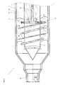
- FIG. 1 shows the front part of a device 1 in a first basic embodiment.
- the device 1 has a container 4 shown in a longitudinal section, through which a main component A is guided, in which by means of the device 1, a minor component B can be stored spirally, whereby an adhesive and / or sealant stream AB is formed.
- a container 4 which is configured as a hollow cylinder and provided with an outlet nozzle 45, a rotatably mounted and with a drive unit (see, eg, Figure 18) connected transfer element 2 is provided, which has a supply channel 21 (shown in section) through which the secondary component B via an end piece 3 in the interior 44 of the container 4 is inserted.
- the main component A is continuously conveyed under pressure through the container 4, while the transfer element 2 is cyclically rotated about an axis z extending coaxially to the axis of the container 4. Consequently, the secondary component B emerging from the outlet opening 30 of the end piece 3 is stored in the form of a helix in the main component A.
- the outlet opening 30 of the end piece 3 is positioned on the one hand by the transfer element 2 and on the other hand by the inner wall 46 of the container 4 about the same distance away. This prevents that the minor component B is stored too close to the outer edge of the main component A and penetrate this outwards and the outer surface of the adhesive and / or sealant AB current or the emitted adhesive and / or sealant bead can contaminate. On the other hand, it is ensured that the secondary component B can rapidly penetrate into its peripheral zones after application of the adhesive and / or sealant stream AB and can cause a rapid hardening of the main component A.
- end pieces 3 are preferably used which allow the position of the outlet opening 30 to be set as desired.
- end pieces 3 are also possible to use end pieces 3 with a matched diameter of the outlet opening 30.
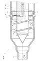
- a simply configured end piece 3 which can be screwed by means of a thread 32 in a provided in the transfer element 2 threaded bore 26 and fixed by a nut 33 at a certain height, is shown in Figure 1a. Through the end piece 3, a bore 31 is guided toward the outlet opening 30.
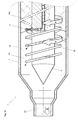
- Figure 2 shows the device of Figure 1 with a transfer element 2 having two end pieces 3 ', 3 "aligned with the supply channel 21 and aligned in opposite directions, adjusted in different ways B "of the minor component B therefore two helicons with different diameters embedded in the flow of the main component A.
- the helix with the larger diameter formed by the component flow B ) has a smaller coil diameter (thickness of the minor component B"), which is why they are closer to the edge of the adhesive and / or Sealant AB can be zoomed without being penetrated by the minor component B ".
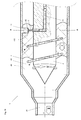
- FIG. 3 shows the device of FIG. 2 with end pieces 3 ', 3 "which are each connected to a separate supply channel 21' or 21". Through the two supply channels 21 'and 21 "partial streams B', B" of the minor component B are supplied, which are preferably individually controlled.
- the helix generated by means of the first partial flow B ' can be pulled through, while the second helix is generated only by segments by sequentially interrupting the second partial flow B "By changing the flow velocities of the component flows B', B", the coil diameters of the helices can also be set , The diameters of the helices themselves can be adjusted by adjusting the end pieces 3 ', 3 "The pitches of the helices are adjustable by selecting the rotational speed of the transfer element 2 and the flow velocity of the main component A.
- the supply channels 21' and 21" also different secondary components in the container 4 can be inserted, so that numerous different applications and reaction processes can be realized.
- the transfer element 2 is rotatably mounted about an axis z, which is aligned coaxially with the axis of the container 4.
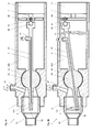
- Figures 4 to 7 show inventive devices 1 in which the transfer element 2 suspended by means of a ball joint and thus rotatable about a point which forms the center of a joint ball 23, which forms the ball joint together with a provided inside the container 4 bearing body 43.
- the ball joint By the ball joint, the interior of the container 4 in a front and a drive side interior 441th or 442 divided.
- the rear end of the transfer element 2 is connected via a rotary joint 87, 88 eccentrically with a round drive plate 86 which is driven by a motor 9 via a drive shaft 7.
- the rotary joint 87, 88 consists of an intermediate shaft 87, which is held displaceably by the drive plate 86 and which is connected to a coupling ball 88 held by the end piece of the transfer element 2.
- the rear end of the transfer element 2 can therefore be rotated in a circle about an axis, which preferably extends coaxially to the axis of the drive shaft 7 through the center of the ball joint 23.
- the front end of the transfer element 2, which forms the delivery of the minor component B end piece 3 protrudes into the front interior 441 of the container 4 and follows with the outlet opening 30 of the end piece 3 also a circular path concentric with the same axis. Therefore, in this embodiment of the device 1, a helix consisting of the minor component B can be incorporated into the main component A penetrating through an inlet opening 47 in the container 4 into the front interior 441 and flowing through it.
- the main component A can be inserted particularly easily into the front-side interior 441 of the container 4.
- the main component A can also be introduced into the container 4 via a plurality of channels, so that a uniform flow of the main component A results.
- FIGS. 4a, 4b and 5 which all show the same configuration of the device 1, the supply channel 21 extends from the outlet opening 30 of the end piece 3 through the ball joint 23 toward the outlet opening 27 at the drive-side end of the transfer element 2.
- the transfer element 2 is aligned in a horizontal plane and turned accordingly; ie the outlet opening 30 is behind.
- the transfer element 2 is aligned in a vertical plane and rotated accordingly; ie the outlet opening 30 is below.
- FIG. 5 shows the device 1 (without outlet nozzle 45) in a spatial representation with the transfer element 2 in the position shown in FIG. 4b.
- the minor component B is introduced directly into the joint ball 23.
- the container 4 of the device 1 shown in Figure 6, in the region of the bearing body 43 has a central portion 443 of the interior, which is sealed against the other two parts 441, 442 of the interior by means of seals 232 and in which the ball joint 23 is mounted.
- the introduced into the middle part 443 of the interior minor component B can penetrate through wide recesses 231 in the ball joint 23 in the supply channel 21 and is further promoted to the outlet opening of the end piece 3.
- connection line 27 for the secondary component B is connected directly to the joint ball 23 by means of a connection element.
- a recess 431 is provided in the bearing body 43, within which the connection line 27 can be moved freely.
- Figure 8 shows a sectional view of the front part of an inventive device 1 in a second basic embodiment with a preferably stationary held transfer element 2 and a rotatably mounted and with a drive unit (not shown) connected to container 4, through which the main component A, during its promotion by the Container 4, is cyclically moved around the transfer element 2.
- the main component A is detected by the inner wall 46 of the container 4, optionally by at least one guide element 42, which rotatably the main component A with the container 4 in the axial direction Outlet nozzle 45 leads out. Due to the stationary holding of the transfer element 2, the secondary components B,... Can be fed in particularly easily.
- the hollow cylindrical container 4 is preferably inserted into a rotatably mounted annular flange 85, which is rotatable about a tube 84, through which the main component A in the container 4 can be inserted.
- FIG. 8 shows schematically that, in addition to the container 4, the transfer element 2 can also be rotatably mounted. In this embodiment, the container 4 and the transfer element 2 are preferably rotated against each other.
- the secondary components B, (C, if present) entering the container 4 through the end pieces 3 are therefore embedded in the flow of the main component A, which passes through the container 4.
- the container 4 In order to prevent the flow of the main component A is detected by the container 4 and rotated, it is guided linearly along a preferably provided guide element 22. In order to prevent rotation of the main component A, the container 4 can also be rotated back and forth.
- the at least one minor component B therefore does not necessarily have to be embedded in the form of a helix in the main component A, as shown in FIG. 9A.
- Secondary component B can follow any line or curve that has a preferably regular course.
- kinematic reversal can be achieved by means of the device 1 of Figure 9, a further advantageous embodiment of the device 1.
- the main component A for example by means of the guide element 22nd rotated while the container 4 is held stationary with the end pieces 3.
- the guide element 22 shown can be connected for this purpose via the drive shaft 7 to the motor 9.
- Figure 10 shows a sectional view of the front part of an inventive device 1 in a third basic embodiment with stationary held and provided with an external thread 29 transfer element 2 and stationarily held and provided with an internal thread 49 container 4, in which the main component A through the internal thread 49 and External thread 29 is moved to the transfer element 2.
- the device 1 in this embodiment therefore does not require a drive device to achieve the desired rotation between the transfer element 2 and the main component A. Only the use of the internal thread 49 or the external thread 29 is possible. By using both threads 29, 49, the movement of the main component A, however, is optimally controlled.
- the device 1 according to the invention is of simple construction in all embodiments and can therefore be manufactured, operated and maintained with little effort.
- direct access to the transfer element 2 and the end pieces 3, 3 ', 3 ", ... is possible so that they can be easily adjusted and cleaned.
- 3 ', 3 "to prevent during operation the device 1 of Figure 11 on the inner wall 46 of the container 4 is provided with a scraper 41, the front contact via an edge 411, the outlet opening 30 of the tail 3 and can free from deposits. With each revolution of the transfer element 2 or the container 4, the outlet opening 30 of the end piece 3 is therefore stripped off, so that the proper functioning of the device 1 is always ensured.
- Scrapers of this or a type described below can be used in all described embodiments of the device 1.
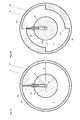
- FIG. 12 shows a section along the line A-A through the device 1 of FIG. 11 provided with a wedge-shaped scraper 41. It can be seen that the edge 411 of the scraper 41 contacts the outlet opening 30 of the end piece 3.
- FIG. 11 shows a section along the line AA through the device 1 of FIG. 11, which is provided with two scrapers 41 ', 41 ", which have the shape of hollow cylinder segments, whereby the outlet opening 30 of the end piece 3 is contacted with a leading edge 411 and then closed by an outer surface 412 of the respective scraper 41 'or 41 ". With each quarter turn of the transfer element 2 against the container 4, the outlet opening 30 is closed and opened again alternately.
- the device 1 is to be provided with at least one scraper 41, 41 ', 41 ", this can be done particularly easily with the container segments 40, 40' shown in FIGS. 14 and 15, which are inexpensive to produce and easy to assemble 16, the container segments 40, 40 'are preferably provided with flange elements 89 which can be screwed to other elements of the container 4.
- the use of container segments 40, 40' further allows the selection of a scraper 41, 41 ', 41 " each adjusted position of the end piece 3 is optimally adapted.
- FIG. 18 shows a device 1 according to the invention in the first basic configuration with a control unit 5, a drive device 9 and supply valves 6A, 6B coupled to one another for the main component A and the secondary component B.
- the supply valves 6A, 6B are constructed in a known manner and have one Valve body 62 A, 62 B on an elastically mounted needle 61 A, 61 B, which closes the outlet of a material chamber 66 A, 66 B, which leads to a transfer hole 67 A, 67 B, through which the main and minor component A, B separated from each other in the container 4 are transferable ,
- the needle 61A, 61B is held by a piston 64A, 64B connected to a pressure chamber 63A, 63B which is depressed by a coil spring 65A, 65B.
- the needle 61A, 61B is lifted and the opening to the transfer hole 67A, 67B exposed, so that the component A, B to be processed enter the transfer hole 67A, 67B from the material chamber 66A, 66B can.
- the front part of the device 1 with the container 4 and the transfer element 2 has been described above.
- the container 4 is inserted into the transfer hole 67A and held by a coupling ring 81.
- a drive shaft 7 is guided, which is introduced on the one hand via a coupling element 91 with a drive motor 9 and on the other hand in a coupling cylinder 28 of the transfer element 2 and anchored there in a metal coupling element 82 by means of coupling pins 83.
- the main component A passes during operation of the device 1 through the first supply valve 6A in the transfer hole 67A and further along the drive shaft 7 in the container 4.
- the in the transfer hole 67B By contrast, reaching secondary component B can only penetrate through a bore in the drive shaft 7 into a shaft channel 71 provided therein, through which the secondary component B is guided to the feed channel 21 of the transfer element 2.
- the supply of the component A and / or B and the motor 9 coupled to the drive shaft 7, are preferably controllable by means of a control unit 5, which is connected to the device 1 according to the invention.
- the density of incorporation of the minor component B can be adjusted by controlling the supply thereof and by changing the rotational speed of the motor 9.
- the formation of the adhesive and / or sealant stream can therefore be adapted in a simple manner to the respective needs of the user.
- the device according to the invention has been described and illustrated in preferred embodiments. On the basis of the teaching according to the invention, however, a variety of further expert designs of the device 1 described can be realized. In particular, the shapes, sizes and material properties of the device elements are selectable in an expert manner. Various valves, if any, and drive devices can be used in a skilled manner. The components to be processed and their dosage are selected depending on the intended application and can be processed in any composition by means of the device 1 according to the invention.
- the adhesives and / or sealants dispensed by the device 1 may be dispensed to a single substrate or, as shown in Figure 19, used to join two or more substrates S1, S2, ....
Landscapes
- Chemical & Material Sciences (AREA)
- Chemical Kinetics & Catalysis (AREA)
- Organic Chemistry (AREA)
- Coating Apparatus (AREA)
- Accessories For Mixers (AREA)
- Sealing Material Composition (AREA)
- Adhesives Or Adhesive Processes (AREA)
Priority Applications (4)
| Application Number | Priority Date | Filing Date | Title |
|---|---|---|---|
| EP05112954A EP1800738A1 (fr) | 2005-12-23 | 2005-12-23 | Dispositif et méthode de formation d'une matière adhésive et/ou d'étanchéité, matière adhésive et/ou d'étanchéité ainsi produite, et substrats collés |
| EP06841591A EP1965897A1 (fr) | 2005-12-23 | 2006-12-22 | Dispositif et procede de formation d'une matiere adhesive et/ou scellante, matiere adhesive et/ou scellante ainsi obtenue et substrat colle |
| JP2008546480A JP2009521304A (ja) | 2005-12-23 | 2006-12-22 | 接着剤および/またはシール材配合物を形成する装置およびプロセス、この方式で生成された接着剤および/またはシール材配合物、ならびに接着剤接合基材 |
| PCT/EP2006/070152 WO2007074139A1 (fr) | 2005-12-23 | 2006-12-22 | Dispositif et procede de formation d’une matiere adhesive et/ou scellante, matiere adhesive et/ou scellante ainsi obtenue et substrat colle |
Applications Claiming Priority (1)
| Application Number | Priority Date | Filing Date | Title |
|---|---|---|---|
| EP05112954A EP1800738A1 (fr) | 2005-12-23 | 2005-12-23 | Dispositif et méthode de formation d'une matière adhésive et/ou d'étanchéité, matière adhésive et/ou d'étanchéité ainsi produite, et substrats collés |
Publications (1)
| Publication Number | Publication Date |
|---|---|
| EP1800738A1 true EP1800738A1 (fr) | 2007-06-27 |
Family
ID=36283908
Family Applications (2)
| Application Number | Title | Priority Date | Filing Date |
|---|---|---|---|
| EP05112954A Withdrawn EP1800738A1 (fr) | 2005-12-23 | 2005-12-23 | Dispositif et méthode de formation d'une matière adhésive et/ou d'étanchéité, matière adhésive et/ou d'étanchéité ainsi produite, et substrats collés |
| EP06841591A Withdrawn EP1965897A1 (fr) | 2005-12-23 | 2006-12-22 | Dispositif et procede de formation d'une matiere adhesive et/ou scellante, matiere adhesive et/ou scellante ainsi obtenue et substrat colle |
Family Applications After (1)
| Application Number | Title | Priority Date | Filing Date |
|---|---|---|---|
| EP06841591A Withdrawn EP1965897A1 (fr) | 2005-12-23 | 2006-12-22 | Dispositif et procede de formation d'une matiere adhesive et/ou scellante, matiere adhesive et/ou scellante ainsi obtenue et substrat colle |
Country Status (3)
| Country | Link |
|---|---|
| EP (2) | EP1800738A1 (fr) |
| JP (1) | JP2009521304A (fr) |
| WO (1) | WO2007074139A1 (fr) |
Cited By (5)
| Publication number | Priority date | Publication date | Assignee | Title |
|---|---|---|---|---|
| WO2015149945A2 (fr) | 2014-04-03 | 2015-10-08 | Dürr Systems GmbH | Mélangeur et procédé de fonctionnement correspondant |
| US20170120288A1 (en) * | 2014-06-12 | 2017-05-04 | Homag Gmbh | Device for preparing and applying adhesive |
| WO2017097693A1 (fr) * | 2015-12-11 | 2017-06-15 | Henkel Ag & Co. Kgaa | Procédé de confectionnement et d'application d'adhésifs |
| CN109603672A (zh) * | 2019-01-09 | 2019-04-12 | 嘉兴椿桦机械有限公司 | 自动制胶装置 |
| CN112024274A (zh) * | 2020-08-25 | 2020-12-04 | 夏志炜 | 一种刀具加工用的快速覆土设备 |
Families Citing this family (1)
| Publication number | Priority date | Publication date | Assignee | Title |
|---|---|---|---|---|
| JP6154785B2 (ja) * | 2014-06-13 | 2017-06-28 | 日本ソセー工業株式会社 | 多液混合型注入機用ミキサー |
Citations (10)
| Publication number | Priority date | Publication date | Assignee | Title |
|---|---|---|---|---|
| US3246883A (en) * | 1963-01-02 | 1966-04-19 | Ashbrook Corp | Fluid mixing method and apparatus |
| US3620507A (en) * | 1970-01-07 | 1971-11-16 | Shell Oil Co | Method for rapidly mixing fluids |
| US3844722A (en) * | 1970-03-17 | 1974-10-29 | Mitsubishi Rayon Co | Apparatus for the continuous preparation of a polymeric solution |
| JPH03267135A (ja) * | 1990-03-16 | 1991-11-28 | Masami Marusawa | 気液混合装置 |
| US6109778A (en) * | 1997-09-22 | 2000-08-29 | United States Filter Corporation | Apparatus for homogeneous mixing of a solution with tangential jet outlets |
| WO2001053191A2 (fr) * | 2000-01-19 | 2001-07-26 | Tuchenhagen Gmbh | Dispositif a ajutages dans un appareil de dissolution pour dissoudre un solide dans un solvant |
| US6488402B1 (en) * | 2001-03-30 | 2002-12-03 | Komax Systems, Inc. | Steam injector and tank mixer |
| US20030173300A1 (en) * | 2002-03-15 | 2003-09-18 | New Earth Systems, Inc. | Leachate and wastewater remediation system |
| DE202004002834U1 (de) * | 2004-02-20 | 2004-06-09 | Nordson Corporation, Westlake | Vorrichtung zur Verklebung zweier Substratflächen |
| DE10343750A1 (de) * | 2003-09-22 | 2005-04-28 | Henkel Kgaa | Polyurethan-Schmelzklebstoffe mit langer Reaktivierbarkeit |
-
2005
- 2005-12-23 EP EP05112954A patent/EP1800738A1/fr not_active Withdrawn
-
2006
- 2006-12-22 JP JP2008546480A patent/JP2009521304A/ja not_active Withdrawn
- 2006-12-22 EP EP06841591A patent/EP1965897A1/fr not_active Withdrawn
- 2006-12-22 WO PCT/EP2006/070152 patent/WO2007074139A1/fr not_active Ceased
Patent Citations (10)
| Publication number | Priority date | Publication date | Assignee | Title |
|---|---|---|---|---|
| US3246883A (en) * | 1963-01-02 | 1966-04-19 | Ashbrook Corp | Fluid mixing method and apparatus |
| US3620507A (en) * | 1970-01-07 | 1971-11-16 | Shell Oil Co | Method for rapidly mixing fluids |
| US3844722A (en) * | 1970-03-17 | 1974-10-29 | Mitsubishi Rayon Co | Apparatus for the continuous preparation of a polymeric solution |
| JPH03267135A (ja) * | 1990-03-16 | 1991-11-28 | Masami Marusawa | 気液混合装置 |
| US6109778A (en) * | 1997-09-22 | 2000-08-29 | United States Filter Corporation | Apparatus for homogeneous mixing of a solution with tangential jet outlets |
| WO2001053191A2 (fr) * | 2000-01-19 | 2001-07-26 | Tuchenhagen Gmbh | Dispositif a ajutages dans un appareil de dissolution pour dissoudre un solide dans un solvant |
| US6488402B1 (en) * | 2001-03-30 | 2002-12-03 | Komax Systems, Inc. | Steam injector and tank mixer |
| US20030173300A1 (en) * | 2002-03-15 | 2003-09-18 | New Earth Systems, Inc. | Leachate and wastewater remediation system |
| DE10343750A1 (de) * | 2003-09-22 | 2005-04-28 | Henkel Kgaa | Polyurethan-Schmelzklebstoffe mit langer Reaktivierbarkeit |
| DE202004002834U1 (de) * | 2004-02-20 | 2004-06-09 | Nordson Corporation, Westlake | Vorrichtung zur Verklebung zweier Substratflächen |
Non-Patent Citations (1)
| Title |
|---|
| PATENT ABSTRACTS OF JAPAN vol. 016, no. 076 (C - 0914) 25 February 1992 (1992-02-25) * |
Cited By (10)
| Publication number | Priority date | Publication date | Assignee | Title |
|---|---|---|---|---|
| WO2015149945A2 (fr) | 2014-04-03 | 2015-10-08 | Dürr Systems GmbH | Mélangeur et procédé de fonctionnement correspondant |
| DE102014004862A1 (de) * | 2014-04-03 | 2015-10-08 | Dürr Systems GmbH | Mischer und entsprechendes Betriebsverfahren |
| WO2015149945A3 (fr) * | 2014-04-03 | 2016-02-04 | Dürr Systems GmbH | Mélangeur et procédé de fonctionnement correspondant |
| US20170120288A1 (en) * | 2014-06-12 | 2017-05-04 | Homag Gmbh | Device for preparing and applying adhesive |
| US10471459B2 (en) * | 2014-06-12 | 2019-11-12 | Homag Gmbh | Device for preparing and applying adhesive |
| WO2017097693A1 (fr) * | 2015-12-11 | 2017-06-15 | Henkel Ag & Co. Kgaa | Procédé de confectionnement et d'application d'adhésifs |
| CN108472605A (zh) * | 2015-12-11 | 2018-08-31 | 汉高股份有限及两合公司 | 用于配混和施加粘合剂的方法 |
| US10981125B2 (en) | 2015-12-11 | 2021-04-20 | Henkel Ag & Co. Kgaa | Method for compounding and applying adhesives |
| CN109603672A (zh) * | 2019-01-09 | 2019-04-12 | 嘉兴椿桦机械有限公司 | 自动制胶装置 |
| CN112024274A (zh) * | 2020-08-25 | 2020-12-04 | 夏志炜 | 一种刀具加工用的快速覆土设备 |
Also Published As
| Publication number | Publication date |
|---|---|
| JP2009521304A (ja) | 2009-06-04 |
| EP1965897A1 (fr) | 2008-09-10 |
| WO2007074139A1 (fr) | 2007-07-05 |
Similar Documents
| Publication | Publication Date | Title |
|---|---|---|
| AT516947B1 (de) | Mischvorrichtung | |
| EP1274501B1 (fr) | Melangeur | |
| EP3368201B1 (fr) | Procédé de confectionnement et d'application d'adhésifs | |
| AT517337B1 (de) | Mischvorrichtung | |
| EP0090257B1 (fr) | Dispositif pour la production d'un mélange chimiquement réactif d'au moins deux composants plastiques liquides | |
| DE102016013785A1 (de) | Reifendichtmittelmischvorrichtung | |
| EP1800738A1 (fr) | Dispositif et méthode de formation d'une matière adhésive et/ou d'étanchéité, matière adhésive et/ou d'étanchéité ainsi produite, et substrats collés | |
| EP0999891A1 (fr) | Dispositif pour stocker des compositions et les exprimer par compression | |
| EP1423299A1 (fr) | Feuilles conferant une couleur et/ou un effet, leur procede de production et leur utilisation | |
| EP0684115B1 (fr) | Procédé pour la fabrication d'un mélange réactif contenant de la matière de remplissage | |
| EP1194466A1 (fr) | Procede et installation pour produire un adhesif thermofusible de polyurethanne | |
| EP1830739A1 (fr) | Melangeur dynamique | |
| DE102010012466B4 (de) | Dosiervorrichtung für einen scherempfindlichen Klebstoff sowie Vorrichtung zur Aufbringung von Klebstoff mit einer derartigen Dosiervorrichtung | |
| EP1728840A1 (fr) | Procédé d'application et de collage | |
| EP1850970B1 (fr) | Dispositif et procede pour melanger un composant liant et un composant durcisseur afin de produire une matiere a enduire prete a l'emploi | |
| EP2651546B1 (fr) | Appareil permettant d'élaborer une masse à jointoyer prête à l'emploi par mélange d'un composant liant et d'un composant durcisseur, et son utilisation | |
| DD141975A3 (de) | Verfahren und vorrichtung zur kontinuierlichen herstellung von polyurethanprodukten | |
| EP3676018A1 (fr) | Dispositifs de dosage et de mélange | |
| WO2006128883A1 (fr) | Adhesif thermofusible a deux composants contenant de l'eau | |
| DE102004015942B3 (de) | Vorrichtung zum Mischen reaktiver Kunststoffe | |
| DE202006007425U1 (de) | Vorrichtung zum Vermischen einer Binder- und einer Härter-Komponente zur Herstellung einer gebrauchsfertigen Spachtelmasse | |
| EP0897063A2 (fr) | Dispositif pour le déplacement de composition d'élastomère | |
| CH401010A (de) | Verfahren und Einrichtung zum innigen Mischen von mehreren Bestandteilen und Auftragen der Mischung | |
| WO2019042772A1 (fr) | Dispositif de dosage et de mélange | |
| WO2003066305A1 (fr) | Procede pour produire des elements en sandwich en polyurethanne |
Legal Events
| Date | Code | Title | Description |
|---|---|---|---|
| PUAI | Public reference made under article 153(3) epc to a published international application that has entered the european phase |
Free format text: ORIGINAL CODE: 0009012 |
|
| AK | Designated contracting states |
Kind code of ref document: A1 Designated state(s): AT BE BG CH CY CZ DE DK EE ES FI FR GB GR HU IE IS IT LI LT LU LV MC NL PL PT RO SE SI SK TR |
|
| AX | Request for extension of the european patent |
Extension state: AL BA HR MK YU |
|
| 17P | Request for examination filed |
Effective date: 20071227 |
|
| AKX | Designation fees paid |
Designated state(s): AT BE BG CH CY CZ DE DK EE ES FI FR GB GR HU IE IS IT LI LT LU LV MC NL PL PT RO SE SI SK TR |
|
| 17Q | First examination report despatched |
Effective date: 20080206 |
|
| STAA | Information on the status of an ep patent application or granted ep patent |
Free format text: STATUS: THE APPLICATION IS DEEMED TO BE WITHDRAWN |
|
| 18D | Application deemed to be withdrawn |
Effective date: 20080617 |