EP1800909A2 - Pneumatic tire - Google Patents
Pneumatic tire Download PDFInfo
- Publication number
- EP1800909A2 EP1800909A2 EP06126107A EP06126107A EP1800909A2 EP 1800909 A2 EP1800909 A2 EP 1800909A2 EP 06126107 A EP06126107 A EP 06126107A EP 06126107 A EP06126107 A EP 06126107A EP 1800909 A2 EP1800909 A2 EP 1800909A2
- Authority
- EP
- European Patent Office
- Prior art keywords
- carcass
- tire
- turnup
- bead
- ply
- Prior art date
- Legal status (The legal status is an assumption and is not a legal conclusion. Google has not performed a legal analysis and makes no representation as to the accuracy of the status listed.)
- Granted
Links
Images


Classifications
-
- B—PERFORMING OPERATIONS; TRANSPORTING
- B60—VEHICLES IN GENERAL
- B60C—VEHICLE TYRES; TYRE INFLATION; TYRE CHANGING; CONNECTING VALVES TO INFLATABLE ELASTIC BODIES IN GENERAL; DEVICES OR ARRANGEMENTS RELATED TO TYRES
- B60C15/00—Tyre beads, e.g. ply turn-up or overlap
- B60C15/06—Flipper strips, fillers, or chafing strips and reinforcing layers for the construction of the bead
-
- B—PERFORMING OPERATIONS; TRANSPORTING
- B60—VEHICLES IN GENERAL
- B60C—VEHICLE TYRES; TYRE INFLATION; TYRE CHANGING; CONNECTING VALVES TO INFLATABLE ELASTIC BODIES IN GENERAL; DEVICES OR ARRANGEMENTS RELATED TO TYRES
- B60C9/00—Reinforcements or ply arrangement of pneumatic tyres
- B60C9/02—Carcasses
- B60C9/04—Carcasses the reinforcing cords of each carcass ply arranged in a substantially parallel relationship
-
- B—PERFORMING OPERATIONS; TRANSPORTING
- B60—VEHICLES IN GENERAL
- B60C—VEHICLE TYRES; TYRE INFLATION; TYRE CHANGING; CONNECTING VALVES TO INFLATABLE ELASTIC BODIES IN GENERAL; DEVICES OR ARRANGEMENTS RELATED TO TYRES
- B60C9/00—Reinforcements or ply arrangement of pneumatic tyres
- B60C9/02—Carcasses
- B60C9/04—Carcasses the reinforcing cords of each carcass ply arranged in a substantially parallel relationship
- B60C9/08—Carcasses the reinforcing cords of each carcass ply arranged in a substantially parallel relationship the cords extend transversely from bead to bead, i.e. radial ply
-
- Y—GENERAL TAGGING OF NEW TECHNOLOGICAL DEVELOPMENTS; GENERAL TAGGING OF CROSS-SECTIONAL TECHNOLOGIES SPANNING OVER SEVERAL SECTIONS OF THE IPC; TECHNICAL SUBJECTS COVERED BY FORMER USPC CROSS-REFERENCE ART COLLECTIONS [XRACs] AND DIGESTS
- Y10—TECHNICAL SUBJECTS COVERED BY FORMER USPC
- Y10T—TECHNICAL SUBJECTS COVERED BY FORMER US CLASSIFICATION
- Y10T152/00—Resilient tires and wheels
- Y10T152/10—Tires, resilient
- Y10T152/10495—Pneumatic tire or inner tube
- Y10T152/10819—Characterized by the structure of the bead portion of the tire
Definitions
- the present invention is directed to a pneumatic tire. More specifically, the present invention is directed to a pneumatic radial tire wherein the bead portion of the tire is designed for improved durability due to the configuration of the turn-up portion of the carcass reinforcing ply.
- a conventional tire bead portion 100 is illustrated in FIG. 7. What is conventionally considered the main portion 104 of a carcass reinforcing ply extends radially inward toward the tire rim and is turned about an inextensible bead core 106 to form a carcass ply turnup 108.
- the carcass ply turn up 108 extends at a single angle ⁇ relative to a radial line tangent to the axially outermost point of the bead core 106 and parallel to the tire equatorial plane.
- the main portion of the carcass when a tire is expanded, the main portion of the carcass is put under tension, pulling the carcass main portion 104 radially upward and the carcass turn up 108 radially inward.
- the carcass ply After inflation and during operation of the tire, when the tire is under deflection, the carcass ply is subject to bending forces and the carcass main portion 104 moves radially inward while the carcass turn up 108 moves radially and axially outward.
- the rubber surrounding the carcass main portion 104 and the carcass turn up 108 due to the adhesion relationship between the rubber and the reinforcing cords of the ply, also is forced to move and the rubber is stressed. The movement of the carcass ply and the surrounding rubber may result in cracking of the rubber in the tire bead portion, decreasing durability of the tire.
- US-B- 6,260,597 discloses a pneumatic tire having multiple cord reinforced chafer layers in the bead portions outward of a carcass ply. Axially outward of the carcass ply turnup, the terminal ends of the chafer layers are all at the same height or radially outward of the terminal end of the carcass ply turnup. Because the axially outer chafer plies are predominately radially outward of the carcass ply terminal end, when the bead portion is subjected to strain during operation, it is the chafer ply ends that are subjected to the greater load and where crack initiation may begin, resulting in reduced bead durability.
- the present invention is directed to a tire according to claim 1 having improved bead durability.
- Dependent claims cover preferred embodiments of the invention.
- the only ply reinforcement layers in the bead portions of the tire are the carcass reinforcing plies.
- Such a tire does not have any cord reinforced chafer layers located wrapped about the carcass reinforcing ply in the bead portion of the tire.
- the terminal end of the chafer layer located axially outward of the bead core is radially inward of the terminal end of the at least one carcass reinforcing ply.
- the tire has two carcass reinforcing plies.
- the inner carcass reinforcing ply has a terminal end radially inward of the terminal end of the outer carcass ply.
- the radially outermost portions of the carcass turnups are both divergent from the main carcass portions of both plies.
- the inner ply if not divergent, terminates radially inward of the minimum distance D MIN .
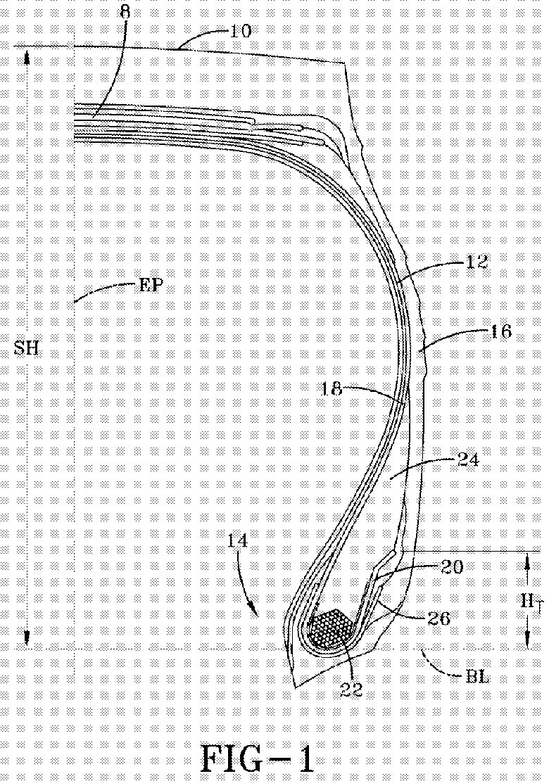
- FIGS. 1 and 2 A pneumatic radial tire in accordance with the present invention is illustrated in FIGS. 1 and 2.
- the pneumatic tire has a carcass, a belt structure 8 radially outward of the carcass, and a tread 10 radially outward of the belt structure 8.
- the belt structure 8 may be any of the type conventionally used for a pneumatic tire, and preferably will include at least two reinforcement plies of angled, inclined cords and may include a ply of zero degree cords.
- the actual belt structure of the tire will be dictated by the intended end use of the tire. Similarly, the exact tread configuration will be dictated by the intended end use of the tire.
- the carcass has at least one carcass reinforcing ply 12, a pair of opposing bead portions 14 and a pair of opposing sidewalls 16.
- the ply 12 has a main portion 18 extending through the opposing sidewalls 16 and two carcass turnups 20 initiating in the bead portions 14.
- Each carcass turnup 20 of the carcass reinforcing ply 12 extends from the main portion 18 of the carcass reinforcing ply 12, and is wrapped about a bead core 22 and a bead apex 24 in the bead portion 14; thus enveloping, at a minimum, the bead core 22 and the lower portion of the bead apex 24 in each bead portion 14.
- the carcass turnup 20 terminates at a distance H T from the tire bead base line BL; the distance H T is at least 20% of the section height SH.
- the tire bead base line BL is an imaginary line, perpendicular to the equatorial plane EP of the tire, from the intersection of the radially extending outerside of the bead portion and the bead base of the tire.
- the chafer 26 extends from axially inward of the bead core 22 to axially outward of the bead core 22, being turned up around the bead core 22 similar to the carcass ply 12.
- the axially outer end of the chafer terminates radially inward of the carcass ply 12.
- the chafer 26 may be omitted from the tire construction so that the only reinforcing cord ply that wraps about the bead core 22 is the carcass ply 12.
- the minimum distance D MIN between the carcass main portion 18 and the carcass turnup 20, as measured perpendicular to the EP is not less than 50%, preferably not less than 75% of the maximum bead core width W B as measured perpendicular to the EP.
- the carcass turnup 20 also does not pass axially inward of a radial line BT that is tangent to the axially outermost point of the bead core 22 and parallel to the tire equatorial plane EP.
- a radially outermost portion 28 of the carcass turnup 20, including the carcass ply terminal end 30, extends at an angle so that the portion 28 of the carcass turnup 20 is divergent, or away, from the carcass main portion 18 that is axially adjacent to the carcass turnup 20.
- the portion 28 extends at an angle ⁇ relative to the equatorial plane EP of the tire, while the adjacent carcass main portion extends at an angle ⁇ relative to the equatorial plane EP.
- the angle ⁇ is in the range of 15° to 75°, preferably 30° to 75°, most preferably 30° to 60°, while the angle difference, ⁇ - ⁇ , between the radially outermost portion 28 and the carcass main portion is at least 10°, preferably equal or greater than 20°.
- the radially outermost portion 28 of the carcass turnup 20 is inclined at an angle ⁇ of 45° relative to the tire EP, and has an angle difference, ⁇ - ⁇ , of 45° - 25°, or 20°.
- FIG. 1 the angle difference between the radially outermost portion 28 and the carcass main portion
- the radially outermost portion 28 of the carcass turnup 20 is inclined at an angle ⁇ of 70° relative to the tire EP, and has an angle difference, ⁇ - ⁇ , with the carcass main portion 18 of 45°.
- the radially outermost portion 28 of the carcass turnup 20 forms an obtuse angle ⁇ with the remainder of the carcass turnup 20.
- the radially outermost portion of the carcass turnup has a length L T in the range of 3 to 20 times the ply cord diameter.
- the diameter of the reinforcing cord is the diameter of circle formed by outermost surface of the reinforcing cord. If the reinforcing cord is a non-circular monofilament, such as an obround monofilament, for the purpose of this invention, the maximum width of the monofilament is the value to use as the diameter.
- FIG. 4 illustrates a bead portion wherein the tire carcass has two reinforcing plies 12 with divergent terminal ends. Both plies 12 have main portions 18 and turnups 20.
- the plies 12 are defined as inner and outer relative to their respective positions at the tire equatorial plane EP.
- the turnup 20' of the inner ply 12' is axially outward of the turnup 20° of the outer ply 12°, with the terminal end 30' of the inner ply 12' being radially inward of the terminal end 30° of the outer ply 12°.
- the radially outermost portion 28' of the inner ply 12' has a configuration similar to the first and outer ply 12°, with the inclination angle ⁇ I of the radially outermost portion 28', relative to the equatorial plane EP being, at a minimum, identical to that of the outer ply 12°.
- the inclination angle ⁇ I may be 5° - 20° greater than the inclination angle ⁇ ° of the outer ply radially outermost portion 28°.
- the terminal end of the inner ply with the non-divergent end, having the radially inner terminal end relative to the terminal end of the outer ply, is located radially inward of the minimum distance D MIN .
- the terminal ends of the plies are staggered, with the outermost ply, defined relative to the respective positions of the plies at the equatorial plane, having a terminal end with the greatest height and b) for terminal ends that are not divergent from the carcass ply main portion, the terminal ends are radially inward of the minimum distance D MIN between the carcass main portions and the carcass turnups.
- FIG. 5 illustrates another embodiment of the present invention.
- the radially outermost portion 28 of the carcass turnup 20 extends at an angle so that the portion 28 is divergent from the carcass main portion, however, leading to the divergence, the carcass turnup 20 is gently curved so as to form a radius R axially outward of the carcass turnup 20, as opposed to the obtuse angle ⁇ as seen in the bead portion 14 of FIG. 3.
- the value of the radius is dependant upon the divergent angle ⁇ formed by the radially outermost portion 28 and the size of the tire.
- This embodiment may also be used with multiple ply carcass structures, with the additional plies meeting the above design criteria.
- a rubber layer 32 is located adjacent to the carcass turnup 20.
- This rubber layer 32 has a hardness comparable to the hardness of the rubber material forming the tire apex 24. If the apex 24 is designed to be formed of multiple rubbers, varying in hardness, the rubber layer 32 has a hardness comparable to the apex rubber closest thereto.
- the carcass plies 12 may be formed from any conventional material, such as, but not limited to, steel, carbon fiber, aramid, nylon, rayon, and polyester. Both the obtuse angle and the radius versions of the bent ply, as discussed above, may be formed from any of the conventional materials, though some materials may be better suited to either the obtuse angle embodiment or the radius embodiment.
- lab samples 40 comprising two plies 42, 44 encased in a rubber rectangle 46 were made having a configuration as shown in FIG. 6.
- the first ply 42 in the sample 40 extends into the rubber 46 at a single angle, with a terminal end 48.
- the second ply 44 extends into the rubber 46 and has a bent terminal end 50.
- the terminal end 48 of the first ply 42 simulates a non-divergent carcass ply terminal end adjacent to a main carcass portion (herein the second ply 44 acts as the main carcass portion) while the bent terminal end 50 of the second ply 44 simulates a divergent carcass ply terminal end adjacent to a main carcass portion (herein the first ply 42 acts as the main carcass portion).
- the samples were subjected to cyclic fatigue testing. During testing the samples were checked and measured for the number of cycles to develop a 1 mm crack, i.e. crack initiation, and for the number of cycles to expand to a 2.5 mm crack, i.e. crack growth life. The results are shown below in the table. Approximate cycles to 1 mm crack Approximate cycles to crack 2.5 mm crack Straight End 175,000 600,000 Bent End 1,200,000 1,950,000
- the tire of the present invention has an improved life and improved bead durability.
- the teachings herein are applicable to a broad range of tires and may be useful in tire lines such as, but not limited to, passenger tires, radial medium truck tires, aircraft tires, and off-the-road tires.
- the teachings may also be useful in improving bead durability for run-flat tires of any type.
Landscapes
- Engineering & Computer Science (AREA)
- Mechanical Engineering (AREA)
- Tires In General (AREA)
- Pharmaceuticals Containing Other Organic And Inorganic Compounds (AREA)
- Acyclic And Carbocyclic Compounds In Medicinal Compositions (AREA)
- Transition And Organic Metals Composition Catalysts For Addition Polymerization (AREA)
Abstract
Description
- The present invention is directed to a pneumatic tire. More specifically, the present invention is directed to a pneumatic radial tire wherein the bead portion of the tire is designed for improved durability due to the configuration of the turn-up portion of the carcass reinforcing ply.
- Bead area durability is one of the concerns of the tire industry. A conventional
tire bead portion 100 is illustrated in FIG. 7. What is conventionally considered themain portion 104 of a carcass reinforcing ply extends radially inward toward the tire rim and is turned about aninextensible bead core 106 to form acarcass ply turnup 108. The carcass ply turn up 108 extends at a single angle µ relative to a radial line tangent to the axially outermost point of thebead core 106 and parallel to the tire equatorial plane. - Due to the configuration and nature of the radial carcass, when a tire is expanded, the main portion of the carcass is put under tension, pulling the carcass
main portion 104 radially upward and the carcass turn up 108 radially inward. After inflation and during operation of the tire, when the tire is under deflection, the carcass ply is subject to bending forces and the carcassmain portion 104 moves radially inward while the carcass turn up 108 moves radially and axially outward. During both tension and deflection, the rubber surrounding the carcassmain portion 104 and the carcass turn up 108, due to the adhesion relationship between the rubber and the reinforcing cords of the ply, also is forced to move and the rubber is stressed. The movement of the carcass ply and the surrounding rubber may result in cracking of the rubber in the tire bead portion, decreasing durability of the tire. - Other attempts have been made to improve the durability of the bead portion.
US-B- 6,260,597 discloses a pneumatic tire having multiple cord reinforced chafer layers in the bead portions outward of a carcass ply. Axially outward of the carcass ply turnup, the terminal ends of the chafer layers are all at the same height or radially outward of the terminal end of the carcass ply turnup. Because the axially outer chafer plies are predominately radially outward of the carcass ply terminal end, when the bead portion is subjected to strain during operation, it is the chafer ply ends that are subjected to the greater load and where crack initiation may begin, resulting in reduced bead durability. This patent teaches that to improve durability, the ends of the chafer plies are bent in various different embodiments while the carcass ply turnup is maintained at a single angle. This solution only works when the chafer plies terminate radially above the carcass ply, and provides no solution for a chaferless tire or a tire wherein the chafer plies terminate radially inward of the carcass ply turnup. - The solution proposed by
US-B- 6,260,597 would not be appreciated by those in the art for such tires as the carcass plies and the cord reinforced chafer plies act differently under tension and deflection. The carcass ply is inclined at a radial angle, extending from bead to bead and so subject to the full tension load and bending forces of the inflated, operating tire while the chafer plies are inclined at bias angles and are only in the bead area and are not subjected to the full tension and deflection of the inflated, operating tire. - The present invention is directed to a tire according to claim 1 having improved bead durability. Dependent claims cover preferred embodiments of the invention.
- In one further aspect of the invention, the only ply reinforcement layers in the bead portions of the tire are the carcass reinforcing plies. Such a tire does not have any cord reinforced chafer layers located wrapped about the carcass reinforcing ply in the bead portion of the tire. In a different embodiment, if the tire does have a cord reinforced chafer layer in each bead portion, the terminal end of the chafer layer located axially outward of the bead core is radially inward of the terminal end of the at least one carcass reinforcing ply.
- In another aspect of the invention, the tire has two carcass reinforcing plies. For such a dual ply tire, with the plies defined relative to one another at the tire equatorial plane, the inner carcass reinforcing ply has a terminal end radially inward of the terminal end of the outer carcass ply. The radially outermost portions of the carcass turnups are both divergent from the main carcass portions of both plies. Alternatively, the inner ply, if not divergent, terminates radially inward of the minimum distance DMIN.
- The invention will be described by way of example and with reference to the accompanying drawings in which:
- FIG. 1 is a cross-sectional view of half of a pneumatic tire;
- FIG. 2 is a close up of the bead portion of the tire of FIG. 1;
- FIGS. 3 - 5 are alternative bead portion constructions;
- FIG. 6 is illustrative of prepared lab samples; and
- FIG. 7 is a prior art tire bead.
- A pneumatic radial tire in accordance with the present invention is illustrated in FIGS. 1 and 2. The pneumatic tire has a carcass, a
belt structure 8 radially outward of the carcass, and atread 10 radially outward of thebelt structure 8. Thebelt structure 8 may be any of the type conventionally used for a pneumatic tire, and preferably will include at least two reinforcement plies of angled, inclined cords and may include a ply of zero degree cords. The actual belt structure of the tire will be dictated by the intended end use of the tire. Similarly, the exact tread configuration will be dictated by the intended end use of the tire. - The carcass has at least one
carcass reinforcing ply 12, a pair ofopposing bead portions 14 and a pair ofopposing sidewalls 16. Theply 12 has amain portion 18 extending through theopposing sidewalls 16 and twocarcass turnups 20 initiating in thebead portions 14. Each carcass turnup 20 of thecarcass reinforcing ply 12 extends from themain portion 18 of thecarcass reinforcing ply 12, and is wrapped about abead core 22 and abead apex 24 in thebead portion 14; thus enveloping, at a minimum, thebead core 22 and the lower portion of thebead apex 24 in eachbead portion 14. Thecarcass turnup 20 terminates at a distance HT from the tire bead base line BL; the distance HT is at least 20% of the section height SH. The tire bead base line BL is an imaginary line, perpendicular to the equatorial plane EP of the tire, from the intersection of the radially extending outerside of the bead portion and the bead base of the tire. - Outward of the
carcass ply 12 in thebead portion 14 is a cord reinforced ply, referred to as thechafer 26. Thechafer 26 extends from axially inward of thebead core 22 to axially outward of thebead core 22, being turned up around thebead core 22 similar to thecarcass ply 12. The axially outer end of the chafer terminates radially inward of thecarcass ply 12. Thechafer 26 may be omitted from the tire construction so that the only reinforcing cord ply that wraps about thebead core 22 is thecarcass ply 12. - To reduce the effect of the shear forces acting on both the carcass
main portion 18 and theturnup portion 20, the minimum distance DMIN between the carcassmain portion 18 and thecarcass turnup 20, as measured perpendicular to the EP, is not less than 50%, preferably not less than 75% of the maximum bead core width WB as measured perpendicular to the EP. Preferably, to maintain the spacing, thecarcass turnup 20 also does not pass axially inward of a radial line BT that is tangent to the axially outermost point of thebead core 22 and parallel to the tire equatorial plane EP. - In accordance with the invention, radially outward of the minimum distance DMIN, a radially
outermost portion 28 of thecarcass turnup 20, including the carcassply terminal end 30, extends at an angle so that theportion 28 of thecarcass turnup 20 is divergent, or away, from the carcassmain portion 18 that is axially adjacent to thecarcass turnup 20. Theportion 28 extends at an angle σ relative to the equatorial plane EP of the tire, while the adjacent carcass main portion extends at an angle α relative to the equatorial plane EP. The angle σ is in the range of 15° to 75°, preferably 30° to 75°, most preferably 30° to 60°, while the angle difference, σ - α, between the radiallyoutermost portion 28 and the carcass main portion is at least 10°, preferably equal or greater than 20°. In the bead portion of FIG. 2, the radiallyoutermost portion 28 of thecarcass turnup 20 is inclined at an angle σ of 45° relative to the tire EP, and has an angle difference, σ - α, of 45° - 25°, or 20°. In the bead portion of FIG. 3, the radiallyoutermost portion 28 of thecarcass turnup 20 is inclined at an angle σ of 70° relative to the tire EP, and has an angle difference, σ - α, with the carcassmain portion 18 of 45°. The radiallyoutermost portion 28 of thecarcass turnup 20 forms an obtuse angle µ with the remainder of thecarcass turnup 20. - Additionally, the radially outermost portion of the carcass turnup has a length LT in the range of 3 to 20 times the ply cord diameter. The diameter of the reinforcing cord is the diameter of circle formed by outermost surface of the reinforcing cord. If the reinforcing cord is a non-circular monofilament, such as an obround monofilament, for the purpose of this invention, the maximum width of the monofilament is the value to use as the diameter.
- FIG. 4 illustrates a bead portion wherein the tire carcass has two reinforcing
plies 12 with divergent terminal ends. Bothplies 12 havemain portions 18 andturnups 20. Theplies 12 are defined as inner and outer relative to their respective positions at the tire equatorial plane EP. The turnup 20' of the inner ply 12' is axially outward of the turnup 20° of theouter ply 12°, with the terminal end 30' of the inner ply 12' being radially inward of theterminal end 30° of theouter ply 12°. The radially outermost portion 28' of the inner ply 12' has a configuration similar to the first and outer ply 12°, with the inclination angle σI of the radially outermost portion 28', relative to the equatorial plane EP being, at a minimum, identical to that of theouter ply 12°. The inclination angle σI may be 5° - 20° greater than the inclination angle σ° of the outer ply radiallyoutermost portion 28°. - If the design guideline for a tire requires two plies but only one ply will have the inventive divergent end, to reduce the stress on the plies in the bead region, the terminal end of the inner ply with the non-divergent end, having the radially inner terminal end relative to the terminal end of the outer ply, is located radially inward of the minimum distance DMIN. For tires requiring more than two plies, the following design criteria are applied: a) the terminal ends of the plies are staggered, with the outermost ply, defined relative to the respective positions of the plies at the equatorial plane, having a terminal end with the greatest height and b) for terminal ends that are not divergent from the carcass ply main portion, the terminal ends are radially inward of the minimum distance DMIN between the carcass main portions and the carcass turnups.
- FIG. 5 illustrates another embodiment of the present invention. The radially
outermost portion 28 of thecarcass turnup 20 extends at an angle so that theportion 28 is divergent from the carcass main portion, however, leading to the divergence, thecarcass turnup 20 is gently curved so as to form a radius R axially outward of thecarcass turnup 20, as opposed to the obtuse angle µ as seen in thebead portion 14 of FIG. 3. The value of the radius is dependant upon the divergent angle σ formed by the radiallyoutermost portion 28 and the size of the tire. This embodiment may also be used with multiple ply carcass structures, with the additional plies meeting the above design criteria. - In the different embodiments of the present invention, to maintain the configuration of the radially
outermost portion 28 of thecarcass turnup 20, arubber layer 32 is located adjacent to thecarcass turnup 20. Thisrubber layer 32 has a hardness comparable to the hardness of the rubber material forming thetire apex 24. If the apex 24 is designed to be formed of multiple rubbers, varying in hardness, therubber layer 32 has a hardness comparable to the apex rubber closest thereto. - In forming the inventive tire, the carcass plies 12 may be formed from any conventional material, such as, but not limited to, steel, carbon fiber, aramid, nylon, rayon, and polyester. Both the obtuse angle and the radius versions of the bent ply, as discussed above, may be formed from any of the conventional materials, though some materials may be better suited to either the obtuse angle embodiment or the radius embodiment.
- To determine the effect of the divergent end of the carcass ply,
lab samples 40 comprising twoplies rubber rectangle 46 were made having a configuration as shown in FIG. 6. Thefirst ply 42 in thesample 40 extends into therubber 46 at a single angle, with aterminal end 48. Thesecond ply 44 extends into therubber 46 and has a bentterminal end 50. Theterminal end 48 of thefirst ply 42 simulates a non-divergent carcass ply terminal end adjacent to a main carcass portion (herein thesecond ply 44 acts as the main carcass portion) while the bentterminal end 50 of thesecond ply 44 simulates a divergent carcass ply terminal end adjacent to a main carcass portion (herein thefirst ply 42 acts as the main carcass portion). - The samples were subjected to cyclic fatigue testing. During testing the samples were checked and measured for the number of cycles to develop a 1 mm crack, i.e. crack initiation, and for the number of cycles to expand to a 2.5 mm crack, i.e. crack growth life. The results are shown below in the table.
Approximate cycles to 1 mm crack Approximate cycles to crack 2.5 mm crack Straight End 175,000 600,000 Bent End 1,200,000 1,950,000 - As seen by the above results, the number of cycles until crack initiation for the bent end was 6.5 times greater than for the straight end. Crack growth life for the bent end was 3.5 times greater than for the straight end. Samples were also built with a ply end bending inward towards the other ply; the test results for such samples failed to show the substantial improvement afforded by the bent-out configuration. Samples were also tested for total fatigue life under different loads; for testing purposes fatigue life was determined to be equivalent to a thirty percent loss of stiffness in the sample. Under an increased load, the bent end ply showed an improvement six fold over the straight end ply.
- The tire of the present invention has an improved life and improved bead durability. The teachings herein are applicable to a broad range of tires and may be useful in tire lines such as, but not limited to, passenger tires, radial medium truck tires, aircraft tires, and off-the-road tires. The teachings may also be useful in improving bead durability for run-flat tires of any type.
Claims (10)
- A pneumatic tire comprising at least one carcass reinforcing ply (12) and a pair of opposing bead portions (14), wherein each bead portion has a bead core (22) and a bead apex (24), wherein the at least one carcass reinforcing ply has a main portion (18) and two turnups (20), one turnup (20) extending from each end of the main portion (18) and having a terminal end (30), wherein the carcass reinforcing ply main portion (18) extends between the opposing bead cores and the turnups (20) are located axially outward of the bead core (22) and a portion of the bead apex (24), the tire being characterized in that in each bead portion (14), there is a minimum distance (DMIN) between the carcass main portion (18) and the carcass turnup (20), as measured perpendicular to the tire equatorial plane (EP), the minimum distance (DMIN) being not less than 50% of the maximum bead core width (WB) as measured perpendicular to the equatorial plane (EP), and in that in each bead portion (14), radially outward of the minimum distance (DMIN), a radially outermost portion (28) of the carcass turnup (20) extends at an angle so the radially outermost portion (28) of the carcass turnup (20) is divergent from the carcass main portion (18).
- The tire of claim 1 wherein the divergence of the radially outermost portion (28) of the carcass turnup (20) from the carcass main portion (18) is the difference between the angle (σ) formed between the radially outermost portion of the carcass turnup, relative to the tire equatorial plane (EP), and the angle (α) formed predominately by the adjacent carcass main portion, relative to the equatorial plane (EP), the angle difference (σ - α) being at least 10°, alternately at least 20°.
- The tire of either claim 1 or 2 wherein the radially outermost portion (28) of the carcass turnup (20) extends at an angle (σ) relative to the equatorial plane (EP) of the tire, the angle being in the range of 15° to 75°, alternately 30° to 60°.
- The tire of at least one of the previous claims wherein the at least one carcass reinforcing ply (12) comprises reinforcing cords, the reinforcing cords having a cross-sectional diameter, and the radially outermost portion (28) of the carcass turnup (20) has a length in the range of 3 to 20 times , alternately 5 to 15 times, the diameter of the reinforcing cords.
- The tire of at least one of the previous claims wherein the divergent radially outermost portion (28) of the carcass turnup (20) forms an obtuse angle with the radially inner portion of the carcass turnup.
- The tire of any of claims 1 to 4 wherein the divergent radially outermost portion (28) of the carcass turnup (20) is curved away from the radially inner portion of the carcass turnup, forming a radius axially outward of the carcass turnup.
- The tire of at least one of the previous claims wherein the tire has two carcass reinforcing plies (12), and the inner carcass reinforcing ply (12') has a terminal end (30') radially inward of the terminal end of the outer carcass ply (12°), and the radially outermost portions (28', 28°) of the carcass turnups are both divergent from the main carcass portions (18) of both plies.
- The tire of at least one of the previous claims wherein the tire has two or more carcass reinforcing plies (12), and the outermost carcass ply (12°) has a divergent radially outermost end (28°) and the terminal ends of the remaining carcass plies are located radially inward of the minimum distance DMIN.
- The tire of at least one of the previous claims wherein the minimum distance (DMIN) is not less than 75% of the maximum bead width (WB).
- The tire of at least one of the previous claims wherein the radially outermost portion (28) of the carcass turnup (20) extends at an angle (σ) relative to the equatorial plane (EP) of the tire, the extending angle being in the range of 30° to 75°.
Applications Claiming Priority (1)
| Application Number | Priority Date | Filing Date | Title |
|---|---|---|---|
| US75241605P | 2005-12-21 | 2005-12-21 |
Publications (3)
| Publication Number | Publication Date |
|---|---|
| EP1800909A2 true EP1800909A2 (en) | 2007-06-27 |
| EP1800909A3 EP1800909A3 (en) | 2008-11-05 |
| EP1800909B1 EP1800909B1 (en) | 2010-11-17 |
Family
ID=37820661
Family Applications (1)
| Application Number | Title | Priority Date | Filing Date |
|---|---|---|---|
| EP06126107A Not-in-force EP1800909B1 (en) | 2005-12-21 | 2006-12-14 | Pneumatic tire |
Country Status (8)
| Country | Link |
|---|---|
| US (1) | US7552754B2 (en) |
| EP (1) | EP1800909B1 (en) |
| JP (1) | JP2007168782A (en) |
| CN (1) | CN1986261B (en) |
| AT (1) | ATE488383T1 (en) |
| BR (1) | BRPI0605309A (en) |
| DE (1) | DE602006018248D1 (en) |
| ES (1) | ES2356042T3 (en) |
Cited By (1)
| Publication number | Priority date | Publication date | Assignee | Title |
|---|---|---|---|---|
| EP2045105A3 (en) * | 2007-10-04 | 2009-12-02 | The Goodyear Tire & Rubber Company | Pneumatic tire |
Families Citing this family (7)
| Publication number | Priority date | Publication date | Assignee | Title |
|---|---|---|---|---|
| US20100065184A1 (en) * | 2008-09-18 | 2010-03-18 | Osama Hamzeh | Reinforcing structure for pneumatic tires |
| JP5560906B2 (en) * | 2010-05-31 | 2014-07-30 | 横浜ゴム株式会社 | Pneumatic tire |
| US8622106B1 (en) * | 2012-08-27 | 2014-01-07 | The Goodyear Tire & Rubber Company | Bead structure for a pneumatic tire |
| FR2999474B1 (en) * | 2012-12-13 | 2016-03-11 | Michelin & Cie | PNEUMATIC BOURRELET FOR HEAVY VEHICLE TYPE GENIE CIVIL |
| CN103223828B (en) * | 2013-05-13 | 2016-03-23 | 中国化工集团曙光橡胶工业研究设计院有限公司 | The meridian aviation tyre of hexagonal bead and the manufacture method of hexagonal bead |
| CN103786526A (en) * | 2013-12-30 | 2014-05-14 | 中国化工橡胶桂林轮胎有限公司 | Optimized back-packaging radial tire |
| DE102024108008A1 (en) * | 2024-03-20 | 2025-09-25 | Continental Reifen Deutschland Gmbh | vehicle tires |
Citations (4)
| Publication number | Priority date | Publication date | Assignee | Title |
|---|---|---|---|---|
| US3612137A (en) | 1967-11-27 | 1971-10-12 | Cta Comp Ind Textiles | Large size tires for trucks and other heavy vehicles |
| US4705091A (en) | 1985-07-24 | 1987-11-10 | Sumitomo Rubber Industries, Ltd. | Heavy duty pneumatic radial tires |
| US5080158A (en) | 1985-05-21 | 1992-01-14 | Sumitomo Rubber Industries, Ltd. | Bead reinforcement for a radial tire for heavy duty |
| US6260597B1 (en) | 1997-06-13 | 2001-07-17 | Bridgestone Corporation | Heavy duty pneumatic radial tires with organic fiber cord bead reinforcing layer |
Family Cites Families (8)
| Publication number | Priority date | Publication date | Assignee | Title |
|---|---|---|---|---|
| FR2075850A1 (en) * | 1969-12-23 | 1971-10-15 | Michelin & Cie | |
| KR940005866B1 (en) * | 1987-10-24 | 1994-06-24 | 가부시끼가이샤 브리지스톤 | Heavy Duty Air Radial Tires |
| JPH02267012A (en) * | 1989-04-04 | 1990-10-31 | Bridgestone Corp | Pneumatic radial tire for heavy load |
| JP3224996B2 (en) * | 1996-11-20 | 2001-11-05 | 住友ゴム工業株式会社 | Radial tires for heavy loads |
| EP0884200B1 (en) * | 1997-06-12 | 2003-11-05 | Bridgestone Corporation | Heavy duty pneumatic radial tyres |
| DE69910523T2 (en) | 1998-10-29 | 2004-03-18 | Sumitomo Rubber Industries Ltd., Kobe | tires |
| US20040007305A1 (en) | 2001-04-16 | 2004-01-15 | Kiyoshi Ueyoko | Pneumatic tire |
| CN1386653A (en) * | 2001-05-21 | 2002-12-25 | 住友橡胶工业株式会社 | Inflated tyre |
-
2006
- 2006-12-06 US US11/634,468 patent/US7552754B2/en not_active Expired - Fee Related
- 2006-12-14 AT AT06126107T patent/ATE488383T1/en not_active IP Right Cessation
- 2006-12-14 DE DE602006018248T patent/DE602006018248D1/en active Active
- 2006-12-14 ES ES06126107T patent/ES2356042T3/en active Active
- 2006-12-14 EP EP06126107A patent/EP1800909B1/en not_active Not-in-force
- 2006-12-18 BR BRPI0605309-2A patent/BRPI0605309A/en not_active IP Right Cessation
- 2006-12-20 JP JP2006342844A patent/JP2007168782A/en active Pending
- 2006-12-21 CN CN2006101724472A patent/CN1986261B/en not_active Expired - Fee Related
Patent Citations (4)
| Publication number | Priority date | Publication date | Assignee | Title |
|---|---|---|---|---|
| US3612137A (en) | 1967-11-27 | 1971-10-12 | Cta Comp Ind Textiles | Large size tires for trucks and other heavy vehicles |
| US5080158A (en) | 1985-05-21 | 1992-01-14 | Sumitomo Rubber Industries, Ltd. | Bead reinforcement for a radial tire for heavy duty |
| US4705091A (en) | 1985-07-24 | 1987-11-10 | Sumitomo Rubber Industries, Ltd. | Heavy duty pneumatic radial tires |
| US6260597B1 (en) | 1997-06-13 | 2001-07-17 | Bridgestone Corporation | Heavy duty pneumatic radial tires with organic fiber cord bead reinforcing layer |
Cited By (1)
| Publication number | Priority date | Publication date | Assignee | Title |
|---|---|---|---|---|
| EP2045105A3 (en) * | 2007-10-04 | 2009-12-02 | The Goodyear Tire & Rubber Company | Pneumatic tire |
Also Published As
| Publication number | Publication date |
|---|---|
| EP1800909A3 (en) | 2008-11-05 |
| CN1986261A (en) | 2007-06-27 |
| JP2007168782A (en) | 2007-07-05 |
| US7552754B2 (en) | 2009-06-30 |
| ATE488383T1 (en) | 2010-12-15 |
| EP1800909B1 (en) | 2010-11-17 |
| US20070137756A1 (en) | 2007-06-21 |
| CN1986261B (en) | 2010-11-24 |
| BRPI0605309A (en) | 2007-10-09 |
| DE602006018248D1 (en) | 2010-12-30 |
| ES2356042T3 (en) | 2011-04-04 |
Similar Documents
| Publication | Publication Date | Title |
|---|---|---|
| EP0795426B1 (en) | Radial tires having at least two belt plies reinforced with steel monofilaments | |
| US20040007305A1 (en) | Pneumatic tire | |
| EP2196327B1 (en) | Pneumatic tire | |
| US5709760A (en) | Thin gauge, fine diameter steel cord reinforced tire ply fabric which is lap spliced | |
| US9272577B2 (en) | Aircraft radial tire | |
| EP2058146B1 (en) | Pneumatic tire | |
| EP0749855A1 (en) | Heavy duty radial tyre | |
| EP0798139A2 (en) | Pneumatic tyre | |
| US6386259B1 (en) | Heavy duty radial tire with specified arrangement of chafer and carcass turnup | |
| EP1080950A2 (en) | Pneumatic tyre | |
| EP0936087B1 (en) | Heavy duty radial tyre | |
| EP2230098A1 (en) | Pneumatic radial tire | |
| US6997224B2 (en) | Tire having an improved carcass reinforcement anchoring structure | |
| US20030111152A1 (en) | Pneumatic tire bead area construction for improved chafer cracking resistance during run-flat operation | |
| US20030150540A1 (en) | Aircraft tire having an improved bead | |
| EP1800909B1 (en) | Pneumatic tire | |
| EP0844109B1 (en) | Heavy duty radial tyre | |
| US6823914B2 (en) | Heavy duty pneumatic radial tires with organic fiber cord bead reinforcing layer | |
| JPWO1998056603A1 (en) | Heavy-duty pneumatic radial tires | |
| US20030005994A1 (en) | Pneumatic tire | |
| US20030155061A1 (en) | Tire having an improved carcass reinforcement anchoring structure | |
| US7011127B2 (en) | Tire for heavy load use | |
| BRPI0612395A2 (en) | tire with radial casing armature | |
| JPH07101212A (en) | Pneumatic radial tire for heavy load | |
| JP2001071717A (en) | Radial tires for heavy loads |
Legal Events
| Date | Code | Title | Description |
|---|---|---|---|
| PUAI | Public reference made under article 153(3) epc to a published international application that has entered the european phase |
Free format text: ORIGINAL CODE: 0009012 |
|
| AK | Designated contracting states |
Kind code of ref document: A2 Designated state(s): AT BE BG CH CY CZ DE DK EE ES FI FR GB GR HU IE IS IT LI LT LU LV MC NL PL PT RO SE SI SK TR |
|
| AX | Request for extension of the european patent |
Extension state: AL BA HR MK YU |
|
| RIN1 | Information on inventor provided before grant (corrected) |
Inventor name: FLEISCHMANN, THOMAS SHERWOOD Inventor name: LICHT, LAURENT Inventor name: NEAL, CHRISTOPHER VINCENT Inventor name: FELLER, JEAN-MARIE Inventor name: BODEUX, JEAN-BERNARD Inventor name: DU, MINGLIANG Inventor name: BOROWCZAK, MARC Inventor name: BO, ZHONGHE Inventor name: WINKIN, DIDIER Inventor name: MACURI, FELIX MAXIMO VILCHEZ Inventor name: AKSHANTALA, NAGENDRA PRASAD VENKATA |
|
| PUAL | Search report despatched |
Free format text: ORIGINAL CODE: 0009013 |
|
| AK | Designated contracting states |
Kind code of ref document: A3 Designated state(s): AT BE BG CH CY CZ DE DK EE ES FI FR GB GR HU IE IS IT LI LT LU LV MC NL PL PT RO SE SI SK TR |
|
| AX | Request for extension of the european patent |
Extension state: AL BA HR MK RS |
|
| 17P | Request for examination filed |
Effective date: 20090506 |
|
| 17Q | First examination report despatched |
Effective date: 20090608 |
|
| AKX | Designation fees paid |
Designated state(s): AT BE BG CH CY CZ DE DK EE ES FI FR GB GR HU IE IS IT LI LT LU LV MC NL PL PT RO SE SI SK TR |
|
| GRAP | Despatch of communication of intention to grant a patent |
Free format text: ORIGINAL CODE: EPIDOSNIGR1 |
|
| GRAS | Grant fee paid |
Free format text: ORIGINAL CODE: EPIDOSNIGR3 |
|
| GRAA | (expected) grant |
Free format text: ORIGINAL CODE: 0009210 |
|
| AK | Designated contracting states |
Kind code of ref document: B1 Designated state(s): AT BE BG CH CY CZ DE DK EE ES FI FR GB GR HU IE IS IT LI LT LU LV MC NL PL PT RO SE SI SK TR |
|
| REG | Reference to a national code |
Ref country code: GB Ref legal event code: FG4D |
|
| REG | Reference to a national code |
Ref country code: CH Ref legal event code: EP |
|
| REG | Reference to a national code |
Ref country code: IE Ref legal event code: FG4D |
|
| REF | Corresponds to: |
Ref document number: 602006018248 Country of ref document: DE Date of ref document: 20101230 Kind code of ref document: P |
|
| REG | Reference to a national code |
Ref country code: NL Ref legal event code: VDEP Effective date: 20101117 |
|
| PGFP | Annual fee paid to national office [announced via postgrant information from national office to epo] |
Ref country code: GB Payment date: 20101215 Year of fee payment: 5 |
|
| REG | Reference to a national code |
Ref country code: ES Ref legal event code: FG2A Ref document number: 2356042 Country of ref document: ES Kind code of ref document: T3 Effective date: 20110404 |
|
| LTIE | Lt: invalidation of european patent or patent extension |
Effective date: 20101117 |
|
| PG25 | Lapsed in a contracting state [announced via postgrant information from national office to epo] |
Ref country code: LT Free format text: LAPSE BECAUSE OF FAILURE TO SUBMIT A TRANSLATION OF THE DESCRIPTION OR TO PAY THE FEE WITHIN THE PRESCRIBED TIME-LIMIT Effective date: 20101117 |
|
| PG25 | Lapsed in a contracting state [announced via postgrant information from national office to epo] |
Ref country code: AT Free format text: LAPSE BECAUSE OF FAILURE TO SUBMIT A TRANSLATION OF THE DESCRIPTION OR TO PAY THE FEE WITHIN THE PRESCRIBED TIME-LIMIT Effective date: 20101117 Ref country code: SI Free format text: LAPSE BECAUSE OF FAILURE TO SUBMIT A TRANSLATION OF THE DESCRIPTION OR TO PAY THE FEE WITHIN THE PRESCRIBED TIME-LIMIT Effective date: 20101117 Ref country code: NL Free format text: LAPSE BECAUSE OF FAILURE TO SUBMIT A TRANSLATION OF THE DESCRIPTION OR TO PAY THE FEE WITHIN THE PRESCRIBED TIME-LIMIT Effective date: 20101117 Ref country code: SE Free format text: LAPSE BECAUSE OF FAILURE TO SUBMIT A TRANSLATION OF THE DESCRIPTION OR TO PAY THE FEE WITHIN THE PRESCRIBED TIME-LIMIT Effective date: 20101117 Ref country code: BG Free format text: LAPSE BECAUSE OF FAILURE TO SUBMIT A TRANSLATION OF THE DESCRIPTION OR TO PAY THE FEE WITHIN THE PRESCRIBED TIME-LIMIT Effective date: 20110217 Ref country code: FI Free format text: LAPSE BECAUSE OF FAILURE TO SUBMIT A TRANSLATION OF THE DESCRIPTION OR TO PAY THE FEE WITHIN THE PRESCRIBED TIME-LIMIT Effective date: 20101117 Ref country code: CY Free format text: LAPSE BECAUSE OF FAILURE TO SUBMIT A TRANSLATION OF THE DESCRIPTION OR TO PAY THE FEE WITHIN THE PRESCRIBED TIME-LIMIT Effective date: 20101117 Ref country code: LV Free format text: LAPSE BECAUSE OF FAILURE TO SUBMIT A TRANSLATION OF THE DESCRIPTION OR TO PAY THE FEE WITHIN THE PRESCRIBED TIME-LIMIT Effective date: 20101117 Ref country code: IS Free format text: LAPSE BECAUSE OF FAILURE TO SUBMIT A TRANSLATION OF THE DESCRIPTION OR TO PAY THE FEE WITHIN THE PRESCRIBED TIME-LIMIT Effective date: 20110317 Ref country code: PT Free format text: LAPSE BECAUSE OF FAILURE TO SUBMIT A TRANSLATION OF THE DESCRIPTION OR TO PAY THE FEE WITHIN THE PRESCRIBED TIME-LIMIT Effective date: 20110317 |
|
| PG25 | Lapsed in a contracting state [announced via postgrant information from national office to epo] |
Ref country code: GR Free format text: LAPSE BECAUSE OF FAILURE TO SUBMIT A TRANSLATION OF THE DESCRIPTION OR TO PAY THE FEE WITHIN THE PRESCRIBED TIME-LIMIT Effective date: 20110218 |
|
| PG25 | Lapsed in a contracting state [announced via postgrant information from national office to epo] |
Ref country code: EE Free format text: LAPSE BECAUSE OF FAILURE TO SUBMIT A TRANSLATION OF THE DESCRIPTION OR TO PAY THE FEE WITHIN THE PRESCRIBED TIME-LIMIT Effective date: 20101117 Ref country code: CZ Free format text: LAPSE BECAUSE OF FAILURE TO SUBMIT A TRANSLATION OF THE DESCRIPTION OR TO PAY THE FEE WITHIN THE PRESCRIBED TIME-LIMIT Effective date: 20101117 Ref country code: MC Free format text: LAPSE BECAUSE OF NON-PAYMENT OF DUE FEES Effective date: 20101231 Ref country code: BE Free format text: LAPSE BECAUSE OF FAILURE TO SUBMIT A TRANSLATION OF THE DESCRIPTION OR TO PAY THE FEE WITHIN THE PRESCRIBED TIME-LIMIT Effective date: 20101117 |
|
| REG | Reference to a national code |
Ref country code: CH Ref legal event code: PL |
|
| PG25 | Lapsed in a contracting state [announced via postgrant information from national office to epo] |
Ref country code: DK Free format text: LAPSE BECAUSE OF FAILURE TO SUBMIT A TRANSLATION OF THE DESCRIPTION OR TO PAY THE FEE WITHIN THE PRESCRIBED TIME-LIMIT Effective date: 20101117 Ref country code: PL Free format text: LAPSE BECAUSE OF FAILURE TO SUBMIT A TRANSLATION OF THE DESCRIPTION OR TO PAY THE FEE WITHIN THE PRESCRIBED TIME-LIMIT Effective date: 20101117 Ref country code: RO Free format text: LAPSE BECAUSE OF FAILURE TO SUBMIT A TRANSLATION OF THE DESCRIPTION OR TO PAY THE FEE WITHIN THE PRESCRIBED TIME-LIMIT Effective date: 20101117 Ref country code: SK Free format text: LAPSE BECAUSE OF FAILURE TO SUBMIT A TRANSLATION OF THE DESCRIPTION OR TO PAY THE FEE WITHIN THE PRESCRIBED TIME-LIMIT Effective date: 20101117 |
|
| PLBE | No opposition filed within time limit |
Free format text: ORIGINAL CODE: 0009261 |
|
| STAA | Information on the status of an ep patent application or granted ep patent |
Free format text: STATUS: NO OPPOSITION FILED WITHIN TIME LIMIT |
|
| 26N | No opposition filed |
Effective date: 20110818 |
|
| PG25 | Lapsed in a contracting state [announced via postgrant information from national office to epo] |
Ref country code: IE Free format text: LAPSE BECAUSE OF NON-PAYMENT OF DUE FEES Effective date: 20101214 Ref country code: LI Free format text: LAPSE BECAUSE OF NON-PAYMENT OF DUE FEES Effective date: 20101231 Ref country code: CH Free format text: LAPSE BECAUSE OF NON-PAYMENT OF DUE FEES Effective date: 20101231 |
|
| REG | Reference to a national code |
Ref country code: DE Ref legal event code: R097 Ref document number: 602006018248 Country of ref document: DE Effective date: 20110818 |
|
| PGFP | Annual fee paid to national office [announced via postgrant information from national office to epo] |
Ref country code: ES Payment date: 20111220 Year of fee payment: 6 |
|
| PG25 | Lapsed in a contracting state [announced via postgrant information from national office to epo] |
Ref country code: LU Free format text: LAPSE BECAUSE OF NON-PAYMENT OF DUE FEES Effective date: 20101214 Ref country code: HU Free format text: LAPSE BECAUSE OF FAILURE TO SUBMIT A TRANSLATION OF THE DESCRIPTION OR TO PAY THE FEE WITHIN THE PRESCRIBED TIME-LIMIT Effective date: 20110518 |
|
| PGFP | Annual fee paid to national office [announced via postgrant information from national office to epo] |
Ref country code: IT Payment date: 20121218 Year of fee payment: 7 Ref country code: TR Payment date: 20121122 Year of fee payment: 7 |
|
| PGFP | Annual fee paid to national office [announced via postgrant information from national office to epo] |
Ref country code: FR Payment date: 20121219 Year of fee payment: 7 |
|
| PGFP | Annual fee paid to national office [announced via postgrant information from national office to epo] |
Ref country code: DE Payment date: 20121221 Year of fee payment: 7 |
|
| GBPC | Gb: european patent ceased through non-payment of renewal fee |
Effective date: 20121214 |
|
| PG25 | Lapsed in a contracting state [announced via postgrant information from national office to epo] |
Ref country code: GB Free format text: LAPSE BECAUSE OF NON-PAYMENT OF DUE FEES Effective date: 20121214 |
|
| REG | Reference to a national code |
Ref country code: ES Ref legal event code: FD2A Effective date: 20140527 |
|
| PG25 | Lapsed in a contracting state [announced via postgrant information from national office to epo] |
Ref country code: ES Free format text: LAPSE BECAUSE OF NON-PAYMENT OF DUE FEES Effective date: 20121215 |
|
| REG | Reference to a national code |
Ref country code: DE Ref legal event code: R119 Ref document number: 602006018248 Country of ref document: DE |
|
| REG | Reference to a national code |
Ref country code: FR Ref legal event code: ST Effective date: 20140829 |
|
| REG | Reference to a national code |
Ref country code: DE Ref legal event code: R119 Ref document number: 602006018248 Country of ref document: DE Effective date: 20140701 |
|
| PG25 | Lapsed in a contracting state [announced via postgrant information from national office to epo] |
Ref country code: DE Free format text: LAPSE BECAUSE OF NON-PAYMENT OF DUE FEES Effective date: 20140701 |
|
| PG25 | Lapsed in a contracting state [announced via postgrant information from national office to epo] |
Ref country code: FR Free format text: LAPSE BECAUSE OF NON-PAYMENT OF DUE FEES Effective date: 20131231 |
|
| PG25 | Lapsed in a contracting state [announced via postgrant information from national office to epo] |
Ref country code: IT Free format text: LAPSE BECAUSE OF NON-PAYMENT OF DUE FEES Effective date: 20131231 |
|
| PG25 | Lapsed in a contracting state [announced via postgrant information from national office to epo] |
Ref country code: TR Free format text: LAPSE BECAUSE OF NON-PAYMENT OF DUE FEES Effective date: 20131214 |
|
| PG25 | Lapsed in a contracting state [announced via postgrant information from national office to epo] |
Ref country code: IT Free format text: LAPSE BECAUSE OF NON-PAYMENT OF DUE FEES Effective date: 20131214 |