EP1800918A1 - Buse d'air à écoulement tourbillonnant - Google Patents
Buse d'air à écoulement tourbillonnant Download PDFInfo
- Publication number
- EP1800918A1 EP1800918A1 EP06025782A EP06025782A EP1800918A1 EP 1800918 A1 EP1800918 A1 EP 1800918A1 EP 06025782 A EP06025782 A EP 06025782A EP 06025782 A EP06025782 A EP 06025782A EP 1800918 A1 EP1800918 A1 EP 1800918A1
- Authority
- EP
- European Patent Office
- Prior art keywords
- air
- guide elements
- air duct
- vent
- air guide
- Prior art date
- Legal status (The legal status is an assumption and is not a legal conclusion. Google has not performed a legal analysis and makes no representation as to the accuracy of the status listed.)
- Granted
Links
Images




Classifications
-
- B—PERFORMING OPERATIONS; TRANSPORTING
- B60—VEHICLES IN GENERAL
- B60H—ARRANGEMENTS OF HEATING, COOLING, VENTILATING OR OTHER AIR-TREATING DEVICES SPECIALLY ADAPTED FOR PASSENGER OR GOODS SPACES OF VEHICLES
- B60H1/00—Heating, cooling or ventilating devices
- B60H1/34—Nozzles; Air-diffusers
- B60H1/3414—Nozzles; Air-diffusers with means for adjusting the air stream direction
-
- B—PERFORMING OPERATIONS; TRANSPORTING
- B60—VEHICLES IN GENERAL
- B60H—ARRANGEMENTS OF HEATING, COOLING, VENTILATING OR OTHER AIR-TREATING DEVICES SPECIALLY ADAPTED FOR PASSENGER OR GOODS SPACES OF VEHICLES
- B60H1/00—Heating, cooling or ventilating devices
- B60H1/34—Nozzles; Air-diffusers
- B60H1/3457—Outlets providing a vortex, i.e. a spirally wound air flow
Definitions
- the invention relates to an air vent, in particular for air conditioning of a vehicle interior.
- air vents are known in various variants. They serve to quickly create a pleasant climate in the vehicle interior. It is their task to carry sufficient air into the interior for this purpose.
- a device for air conditioning an interior in particular a vehicle air conditioning device, with an air conditioner with a climatic air guide, and with an air heater with a heating air guide.
- the climatic air guide and the heating air guide are connected to the interior and brought together via a mouthpiece in the form of a double nozzle, which has an inner tube and a concentric outer tube. It can be provided in the annular space between the inner tube and outer tube a swirl flow guide, which is preferably adjustable.
- This device is a two-channel air vent with an inner air duct for a concentrated air jet (also called a spot area) and an outer air duct for a swirl flow (also called the diffuse area).
- a concentrated air jet also called a spot area
- an outer air duct for a swirl flow also called the diffuse area.
- the diffuser area In the fully open position, the diffuser area has a high pressure drop and a strong noise. The efficiency of the spot area is thereby reduced.
- the DE 299 14 962 U1 describes a single-channel air vent, in particular for a motor vehicle ventilation, with a swirl generator, which has a plurality of guide vanes, which are each pivotable about a pivot axis.
- the pivot axes are arranged approximately radially about a common central axis, wherein a rotational movement of the central axis can be transmitted as a pivoting movement on the pivot axes of the guide vanes.
- the guide shafts associated with the pivot axes are each rotatably connected to a connecting rod with slot, which are in driving connection with a central friction or gear of the central axis.
- the central axis carries at its downstream axle end a manually operable rotary mechanism.
- the invention has for its object to provide a Heilausströmer of the type mentioned above, which allows a simple design an adaptation of an air conditioning effect, with a wide range of variation of the adjustment should be possible.
- the invention proposes an air vent with at least one air duct and arranged therein air guide elements, wherein by means of adjusting the air guide elements at least one helix for generating an adjustable swirl flow can be formed.
- helix is any structure which continues rotating in the depth of the space.
- such a structure may also be formed in sections in a linear, helical, helical or spiral helix.
- the Lucasieitetemente are preferably correspondingly curved or flat.
- the air vent according to the invention has a plurality of adjustable in position air guide elements, which form at least one adjustable helix, which is divided into at least two sub-segments.
- the sub-segments are formed in a simple manner by the air guide elements.
- the at least one helix is present in a continuous shape.
- the helix is interrupted.
- the air guide elements then act less obstructive than in the helical position in which the helix is present continuously. This reduces the loss of pressure and the noise in the diffuser area when the helix is not used.
- a special embodiment of the air duct is designed as a ring tube and arranged as an outer air duct around a central element around. In this way, a single-channel, annular Heilausströmer be provided with an advantageous adjustable helix.
- the air duct surrounds at least one further air duct and runs parallel to it.
- an outer, annular air duct surrounds an inner, cylindrical air duct.
- a flap in the inner air duct which is connected to a control element which serves to adjust the air guide elements in the outer air duct.
- the air elements which control the swirl flow for the diffuse flow in the outer air duct simultaneously with the flap for adjusting the spot-shaped flow adjustable. Since the at least one adjustable helix in particular causes a reduced pressure loss in the outer air duct, so efficient ventilation is adjustable with a single operation.
- the operating element is designed as an adjusting ring at an outlet opening of the air vent and surrounds both air ducts. This allows easy operation of the air vent for different types of ventilation.
- a mechanical connection to the air guide elements can be produced in a simple manner along the outer air duct.
- a first preferred embodiment of the invention is characterized by exactly two helices, which are formed by a corresponding number of air guide elements.
- a third preferred embodiment of the invention is apparent. through exactly six helices.
- the helices run very steeply inside the outer air duct. According to the concept of the invention, embodiments with three, four, five or more than six helices are also possible. The formation of several helices, for example six, results in a uniform flow profile at the outlet of the air vent.
- a plurality of the air guiding elements are expediently adjustable by means of adjusting elements.
- the adjusting elements are designed as gears or toothed segments.
- the gears or toothed segments preferably engage in Teeth of an outer air duct surrounding the actuating ring.
- the positive connection by adjusting in the form of gears or toothed segments with a ring gear allows high reliability of at least one adjustable helix.
- a plurality of the air guide elements are adjustable by means of adjusting elements, which are designed as engaging in slide guides rotary lever.
- the slotted guides are preferably arranged in a surrounding the outer air duct actuating ring. The positive connection by adjusting in the form of engaging in slide guides rotary levers also allows high reliability of at least one adjustable helix.
- the air guide elements are advantageously designed to be flexible and mounted twistable.
- the bearings of the flexible air guide elements are preferably rotatable by means of an operating ring surrounding the outer air duct. This design also allows a high reliability of the at least one adjustable helix.
- an actuating ring surrounding the outer air duct consists of at least two interconnected parts. This allows easy installation of the actuating ring.
- the parts of the actuating ring are snapped together. This represents a simple and reliable way of connection.
- the air ducts are cylindrical and coaxial. This allows a simple production and a symmetrical flow pattern.
- Embodiments in which the air guiding elements have a straight edge on an inner side of the outer air duct are preferred.
- a central element or an inner channel is preferably provided with straight sealing edges in the region of a helical position of the air guiding elements.
- the helix lies close to the central element or to the inner channel at the inner edge. A pressure drop in this area is thus avoided.
- the invention following air vents are arranged in the vehicle interior, which are in particular carried out individually and / or repeatedly coupled in their adjustment options.
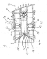
- the air vent 1 shown in Figure 1 has an outer air duct 2 for a diffuse ventilation and an inner air duct 3 for a spot-shaped ventilation.
- the inner air duct 3 extends in an inner cylinder 4 and is surrounded by the outer air duct 2.
- the outer air duct 2 extends parallel to the inner air duct 3 between the inner cylinder 4 and an outer cylinder 5 concentric therewith.
- the inner cylinder 4 is displaced from its actual position in the illustration.
- each helix 6.1, 6.2 consists of three sub-segments each, which form adjustable air guide elements 6A, 6B, 6C.
- the air guide elements 6A to 6C are rotatably mounted for this purpose on the one hand on the inner cylinder 4 and on the other hand on the outer cylinder 5.
- the air guiding elements 6A, 6B, 6C are curved in accordance with a uniform parameterization of the helices 6.1, 6.2. In the illustrated state, two edges of adjacent air guide elements 6A, 6B and 6B, 6C abut one another flush so that the helices 6.1, 6.2 have continuous surfaces and generate a swirl flow in the outer air guide channel 2.
- an actuating ring 7 is arranged, which is composed of three Drnappten parts together.
- the actuating ring 7 has a plurality of offset groups of teeth 8A, 8B, 8C.
- Corresponding adjusting elements which in this case are designed as toothed segments 9, are connected to the air guiding elements 6A, 6B, 6C.
- only one sector gear 9 is shown.
- the adjusting elements with a toothed segment can also be made in one piece.
- the air guiding elements 6A, 6B, 6C have straight edges 10 on their sides facing the inner cylinder 4.
- straight sealing edges 11 are arranged so that they with the edges 10 of the air guide elements 6 A, 6 B, 6 C just in the position of the closed Helices 6.1, 6.2 correspond.
- the sealing edges 11 form a closed hexagon.
- the air guide elements 6A, 6B, 6C are moved over the actuating ring 7, the helices 6.1, 6.2 are thereby interrupted. The swirl caused in the flow is thereby reduced. The pressure drop in the outer air duct 2 is reduced due to the changed effect of the air guide elements 6A, 6B, 6C as flow obstacles.
- the angle of attack of the air guide elements 6A, 6B, 6C can be adjusted by the degree of rotation of the actuating ring 7 in a wide range. By oppositely rotating the actuating ring 7, the closed state of the helix 6 can be restored.
- FIGS. 2 a to 2 d show a further air vent 1 with outer air duct 2 and inner air duct 3. It has six adjustable helices 6.1 to 6.6, which are arranged at the same height in the outer air duct 2. Each helix 6.1 to 6.6 consists of two adjustable by rotation air guide elements 6A and 6B. The air guide elements 6A, 6B are flat, so that the helices 6.1 to 6.6 are piecewise linear.
- FIG. 2a the helices 6.1 to 6.6 are shown fully open. They have minimal pressure drop and noise in this position.
- FIGS. 2b to 2d each helix 6.1 to 6.6 is closed continuously.
- fixed spokes 12 are arranged in the outer air duct 2, which are formed as to the cylinders 4, 5 parallel air guide elements.
- the fixed spokes 12 act as third subsegments of the respective helix 6.1 to 6.6 (see FIG. 2b).
- a flap 13 is arranged, by means of which the inner air duct 3 can be closed (see Figure 2a).
- the Closing mechanism of the flap 13 is positively connected to the actuating ring 7.
- the actuating ring 7 is composed as shown in Figure 1 of several parts. He has six slots as slide guides 14. In the slide guides 14 engage rotary lever 15, which are connected to the respective air guide elements 6A, 6B and thus serve as adjusting elements. During a rotational movement of the actuating ring 7, the slide guides 14 cause a common rotation of all twelve air guide elements 6A, 6B.
- the positive connection with the flap 13 causes a simultaneous opening or closing of the flap 13.
- the flap In the, the air duct 3 opening position, the flap is located substantially in the plane of the axis of the air duct 3.
- the actuating ring 7 is connected in a manner not shown with an operating element 16 which is arranged on the outflow opening 17 of the air vent 1.
- the actuating ring 7 is formed as a ring, which surrounds both air ducts 2, 3.
- the actuating ring 7 is connected to the operating element 16 such that a rotation of the operating element 16 causes a rotation of the actuating ring 7 in the same direction.
- the air guide elements 6A, 6B are adjusted by means of the operating element 16 via the actuating ring 7 and the rotary lever 15 from the position shown in FIG. 2b, for example, the helices 6.1 to 6.6 are interrupted and the flap 13 is opened. The swirl caused in the flow is thereby reduced. The pressure drop in the outer air duct 2 is considerably reduced as Strömungshindemisse due to the changed effect of the air guide elements 6A, 6B.
- the angle of attack of the air guide elements 6A, 6B can be adjusted by the degree of rotation of the control element 16 in a wide range. By reversing, the closed state of the helices 6.1 to 6.6 and the closed flap 13 can be restored. End flaps 18 in the region of the outer air duct 2 can be operated separately.
- FIG. 3 shows another air vent 1 with inner air duct 3 and outer air duct 2, in which four helices 6.1 to 6.4 are formed from a single, respectively flexible air guiding element 6A.
- the flexible air guide elements 6A are rotatably mounted at both ends on the inner cylinder 4 and on the outer cylinder 5 in such a way that they can be twisted by rotating the bearings.
- the bearings are rotatable about a not shown actuating ring which surrounds both air ducts 2, 3.
- the air vent 1 is also provided with end flaps 18, by means of which both air ducts 2, 3 are jointly closed.
- the air guiding elements 6A are twisted by means of the actuating ring, the helices 6.1 to 6.4 are thereby deformed. The swirl caused in the flow is thereby reduced. The pressure drop in the outer air duct 2 is considerably reduced due to the changed effect of the Lufleftimplantation 6A as flow obstacles.
- the twisting of the air guiding elements 6A can be adjusted by the degree of rotation of the operating element 16 in a wide range. Reversing can restore the state of helices 6.1 through 6.4.
- the end flap 18 can be operated separately.
- adjusting elements in the form of toothed segments, gears, rotary levers and rotatable bearings can be combined as desired.
Landscapes
- Physics & Mathematics (AREA)
- Thermal Sciences (AREA)
- Engineering & Computer Science (AREA)
- Mechanical Engineering (AREA)
- Air-Flow Control Members (AREA)
- Air-Conditioning For Vehicles (AREA)
- Preliminary Treatment Of Fibers (AREA)
- Spinning Or Twisting Of Yarns (AREA)
- Telephone Function (AREA)
- Absorbent Articles And Supports Therefor (AREA)
- Respiratory Apparatuses And Protective Means (AREA)
Applications Claiming Priority (1)
| Application Number | Priority Date | Filing Date | Title |
|---|---|---|---|
| DE102005061722A DE102005061722A1 (de) | 2005-12-21 | 2005-12-21 | Luftausströmer mit Drallströmung |
Publications (2)
| Publication Number | Publication Date |
|---|---|
| EP1800918A1 true EP1800918A1 (fr) | 2007-06-27 |
| EP1800918B1 EP1800918B1 (fr) | 2009-09-09 |
Family
ID=37728393
Family Applications (1)
| Application Number | Title | Priority Date | Filing Date |
|---|---|---|---|
| EP06025782A Not-in-force EP1800918B1 (fr) | 2005-12-21 | 2006-12-13 | Buse d'air à écoulement tourbillonnant |
Country Status (3)
| Country | Link |
|---|---|
| EP (1) | EP1800918B1 (fr) |
| AT (1) | ATE442273T1 (fr) |
| DE (2) | DE102005061722A1 (fr) |
Cited By (10)
| Publication number | Priority date | Publication date | Assignee | Title |
|---|---|---|---|---|
| EP1972476A1 (fr) * | 2007-03-20 | 2008-09-24 | Behr GmbH & Co. KG | Extracteur d'air avec écoulement giratoire et flux dirigé |
| WO2010006760A1 (fr) * | 2008-07-16 | 2010-01-21 | Behr Gmbh & Co. Kg | Soufflerie d’air avec écoulement giratoire et écoulement dirigé |
| WO2010069001A1 (fr) | 2008-12-19 | 2010-06-24 | Kaip Pty Limited | Diffuseur d'air et système de circulation d'air |
| EP2272698A3 (fr) * | 2009-07-07 | 2011-01-26 | Behr GmbH & Co. KG | Buse d'écoulement d'air |
| WO2011032694A1 (fr) * | 2009-09-15 | 2011-03-24 | Trw Automotive Electronics & Components Gmbh | Dispositif giratoire pour un diffuseur d'air |
| EP2258572A3 (fr) * | 2009-06-05 | 2011-04-13 | Behr GmbH & Co. KG | Aérateur |
| CN103625244A (zh) * | 2013-11-28 | 2014-03-12 | 富卓汽车内饰(安徽)有限公司 | 一种汽车仪表板 |
| DE102014208589A1 (de) | 2014-05-07 | 2015-11-12 | Mahle International Gmbh | Luftausströmer |
| CN106739966A (zh) * | 2016-12-30 | 2017-05-31 | 滁州舜宇模具有限责任公司 | 一种涡轮叶片式汽车出风口 |
| US20230280067A1 (en) * | 2020-09-29 | 2023-09-07 | Panasonic Intellectual Property Management Co., Ltd. | Airflow control system, airflow control method, and program |
Families Citing this family (10)
| Publication number | Priority date | Publication date | Assignee | Title |
|---|---|---|---|---|
| DE102008050180B4 (de) * | 2008-10-01 | 2013-06-20 | AKT altmärker Kunststoff-Technik GmbH | Luftauslassdüse |
| DE102010040160A1 (de) | 2010-09-02 | 2012-03-08 | Behr Gmbh & Co. Kg | Luftausströmer |
| DE102013213277A1 (de) * | 2013-07-05 | 2015-01-08 | Behr Gmbh & Co. Kg | Luftausströmer |
| DE102013213459A1 (de) | 2013-07-09 | 2015-01-15 | Behr Gmbh & Co. Kg | Luftausströmer |
| DE102014001032A1 (de) | 2014-01-25 | 2014-08-14 | Daimler Ag | Luftausströmer, vorzugsweise für einen Innenraum eines Kraftfahrzeuges |
| DE102014205692A1 (de) | 2014-03-27 | 2015-10-01 | Mahle International Gmbh | Luftausströmer |
| DE102015206609A1 (de) | 2015-04-14 | 2016-10-20 | Mahle International Gmbh | Luftstromsteuereinheit |
| DE102015206621A1 (de) | 2015-04-14 | 2016-10-20 | Mahle International Gmbh | Luftstromsteuereinheit |
| US11738624B2 (en) | 2020-08-12 | 2023-08-29 | Ford Global Technologies, Llc | Air register assembly |
| DE102022115238A1 (de) | 2022-06-20 | 2023-12-21 | Fischer Automotive Systems Gmbh & Co. Kg | Luftausströmer |
Citations (4)
| Publication number | Priority date | Publication date | Assignee | Title |
|---|---|---|---|---|
| DE2902733A1 (de) * | 1979-01-25 | 1980-08-07 | Kessler & Luch Gmbh | Luft-drallauslass fuer klimaanlagen |
| DE3736448A1 (de) * | 1987-10-28 | 1989-05-11 | Ltg Lufttechnische Gmbh | Luftdrallauslass und verfahren zu seinem betreiben |
| DE29914962U1 (de) * | 1999-08-26 | 1999-10-14 | Bermes, Peter, 79232 March | Luftauslaß, insbesondere für eine Kraftfahrzeug-Lüftung |
| WO2005016673A1 (fr) * | 2003-08-11 | 2005-02-24 | Behr Gmbh & Co. Kg | Systeme d'echappement d'air, notamment pour une automobile |
Family Cites Families (5)
| Publication number | Priority date | Publication date | Assignee | Title |
|---|---|---|---|---|
| FR2774633B1 (fr) * | 1998-02-10 | 2000-05-05 | Regie Autonome Transports | Installation de ventilation forcee, notamment pour vehicule |
| DE10036776A1 (de) * | 2000-07-28 | 2002-02-07 | Eberspaecher J Gmbh & Co | Einrichtung zur Klimatisierung eines Innenraumes mit Klimagerät und Luftheizgerät, insbesondere für ein Kraftfahrzeug |
| DE102005036159B4 (de) * | 2005-01-10 | 2014-05-28 | Behr Gmbh & Co. Kg | Luftstromsteuereinheit |
| DE102004003059B4 (de) * | 2003-01-20 | 2010-10-28 | Behr Gmbh & Co. Kg | Luftstromsteuereinheit |
| US9296277B2 (en) * | 2003-03-13 | 2016-03-29 | Mahle International Gmbh | Air exhausting device, in particular for a vehicle and corresponding method for exhausting air |
-
2005
- 2005-12-21 DE DE102005061722A patent/DE102005061722A1/de not_active Withdrawn
-
2006
- 2006-12-13 EP EP06025782A patent/EP1800918B1/fr not_active Not-in-force
- 2006-12-13 AT AT06025782T patent/ATE442273T1/de not_active IP Right Cessation
- 2006-12-13 DE DE502006004784T patent/DE502006004784D1/de active Active
Patent Citations (4)
| Publication number | Priority date | Publication date | Assignee | Title |
|---|---|---|---|---|
| DE2902733A1 (de) * | 1979-01-25 | 1980-08-07 | Kessler & Luch Gmbh | Luft-drallauslass fuer klimaanlagen |
| DE3736448A1 (de) * | 1987-10-28 | 1989-05-11 | Ltg Lufttechnische Gmbh | Luftdrallauslass und verfahren zu seinem betreiben |
| DE29914962U1 (de) * | 1999-08-26 | 1999-10-14 | Bermes, Peter, 79232 March | Luftauslaß, insbesondere für eine Kraftfahrzeug-Lüftung |
| WO2005016673A1 (fr) * | 2003-08-11 | 2005-02-24 | Behr Gmbh & Co. Kg | Systeme d'echappement d'air, notamment pour une automobile |
Cited By (16)
| Publication number | Priority date | Publication date | Assignee | Title |
|---|---|---|---|---|
| EP1972476A1 (fr) * | 2007-03-20 | 2008-09-24 | Behr GmbH & Co. KG | Extracteur d'air avec écoulement giratoire et flux dirigé |
| WO2010006760A1 (fr) * | 2008-07-16 | 2010-01-21 | Behr Gmbh & Co. Kg | Soufflerie d’air avec écoulement giratoire et écoulement dirigé |
| CN102099212B (zh) * | 2008-07-16 | 2013-11-20 | 贝洱两合公司 | 具有涡流和直流的空气发射器 |
| RU2518092C2 (ru) * | 2008-07-16 | 2014-06-10 | Бер Гмбх Унд Ко. Кг | Воздуховыпускное устройство |
| US9802464B2 (en) | 2008-07-16 | 2017-10-31 | Mahle International Gmbh | Air outlet with vortex flow and directed flow |
| US9513026B2 (en) | 2008-12-19 | 2016-12-06 | Kaip Pty Limited | Air diffuser and air circulation system |
| WO2010069001A1 (fr) | 2008-12-19 | 2010-06-24 | Kaip Pty Limited | Diffuseur d'air et système de circulation d'air |
| EP2379950A4 (fr) * | 2008-12-19 | 2012-11-07 | Kaip Pty Ltd | Diffuseur d'air et système de circulation d'air |
| EP2258572A3 (fr) * | 2009-06-05 | 2011-04-13 | Behr GmbH & Co. KG | Aérateur |
| EP2272698A3 (fr) * | 2009-07-07 | 2011-01-26 | Behr GmbH & Co. KG | Buse d'écoulement d'air |
| WO2011032694A1 (fr) * | 2009-09-15 | 2011-03-24 | Trw Automotive Electronics & Components Gmbh | Dispositif giratoire pour un diffuseur d'air |
| CN103625244A (zh) * | 2013-11-28 | 2014-03-12 | 富卓汽车内饰(安徽)有限公司 | 一种汽车仪表板 |
| DE102014208589A1 (de) | 2014-05-07 | 2015-11-12 | Mahle International Gmbh | Luftausströmer |
| CN106739966A (zh) * | 2016-12-30 | 2017-05-31 | 滁州舜宇模具有限责任公司 | 一种涡轮叶片式汽车出风口 |
| CN106739966B (zh) * | 2016-12-30 | 2018-11-16 | 滁州舜宇模具有限责任公司 | 一种涡轮叶片式汽车出风口 |
| US20230280067A1 (en) * | 2020-09-29 | 2023-09-07 | Panasonic Intellectual Property Management Co., Ltd. | Airflow control system, airflow control method, and program |
Also Published As
| Publication number | Publication date |
|---|---|
| DE102005061722A1 (de) | 2007-06-28 |
| EP1800918B1 (fr) | 2009-09-09 |
| DE502006004784D1 (de) | 2009-10-22 |
| ATE442273T1 (de) | 2009-09-15 |
Similar Documents
| Publication | Publication Date | Title |
|---|---|---|
| EP1800918B1 (fr) | Buse d'air à écoulement tourbillonnant | |
| EP2139709B1 (fr) | Aérateur à écoulement turbulent et écoulement classique | |
| EP1923242B1 (fr) | Dispositif d'écoulement d'air avec écoulement giratoire et écoulement conventionnel | |
| EP1972476B1 (fr) | Extracteur d'air avec écoulement giratoire et flux dirigé | |
| DE102018005002B4 (de) | Luftausströmer für einen Kraftwagen, insbesondere für einen Personenkraftwagen | |
| EP3192684B1 (fr) | Dispositif de déplacement de lamelles d'un diffuseur d'air | |
| EP3530506B1 (fr) | Dispositif d'écoulement d'air | |
| DE102018122999A1 (de) | Luftausströmer | |
| DE202017102616U1 (de) | Luftausströmer zur Verwendung in einem Fahrzeug | |
| DE102012015519A1 (de) | Luftleitvorrichtung für eine Luftausströmvorrichtung eines Fahrzeugs | |
| EP3546258A1 (fr) | Dispositif d'écoulement d'air | |
| DE102007018022A1 (de) | Luftdüse | |
| EP1826043A1 (fr) | Tuyère d'air | |
| EP1785298B1 (fr) | Buse d'air | |
| EP1270286B1 (fr) | Dispositif pour diriger l'air, notamment pour un véhicule | |
| EP1985482A2 (fr) | Aérateur | |
| EP1911616B1 (fr) | Tuyère d'air destinée à l'aération d'un espace intérieur de véhicule | |
| DE102008005985B4 (de) | Luftausströmer | |
| EP1747109B1 (fr) | Ejecteur d'air, notamment pour automobile | |
| DE102008004189A1 (de) | Luftausströmer | |
| EP1953017B1 (fr) | Dispositif d'écoulement d'air | |
| DE102010035079A1 (de) | Luftausströmvorrichtung für ein Fahrzeug | |
| DE102022207513B4 (de) | Luftausströmer für ein Fahrzeug | |
| DE102011114766B4 (de) | Lüftungs- und Heizungsmodul für Kraftfahrzeuge mit wenigstens einem Luftführungskanal | |
| DE102012204555A1 (de) | Luftausströmer |
Legal Events
| Date | Code | Title | Description |
|---|---|---|---|
| PUAI | Public reference made under article 153(3) epc to a published international application that has entered the european phase |
Free format text: ORIGINAL CODE: 0009012 |
|
| AK | Designated contracting states |
Kind code of ref document: A1 Designated state(s): AT BE BG CH CY CZ DE DK EE ES FI FR GB GR HU IE IS IT LI LT LU LV MC NL PL PT RO SE SI SK TR |
|
| AX | Request for extension of the european patent |
Extension state: AL BA HR MK YU |
|
| RIN1 | Information on inventor provided before grant (corrected) |
Inventor name: BENAMIRA, SALAH Inventor name: KLINGLER, DIETRICH, DIPL.-ING. Inventor name: LANG, MATTHIAS Inventor name: GROSSMANN, SEBASTIAN |
|
| 17P | Request for examination filed |
Effective date: 20071227 |
|
| 17Q | First examination report despatched |
Effective date: 20080204 |
|
| AKX | Designation fees paid |
Designated state(s): AT BE BG CH CY CZ DE DK EE ES FI FR GB GR HU IE IS IT LI LT LU LV MC NL PL PT RO SE SI SK TR |
|
| GRAP | Despatch of communication of intention to grant a patent |
Free format text: ORIGINAL CODE: EPIDOSNIGR1 |
|
| GRAS | Grant fee paid |
Free format text: ORIGINAL CODE: EPIDOSNIGR3 |
|
| GRAA | (expected) grant |
Free format text: ORIGINAL CODE: 0009210 |
|
| AK | Designated contracting states |
Kind code of ref document: B1 Designated state(s): AT BE BG CH CY CZ DE DK EE ES FI FR GB GR HU IE IS IT LI LT LU LV MC NL PL PT RO SE SI SK TR |
|
| REG | Reference to a national code |
Ref country code: GB Ref legal event code: FG4D Free format text: NOT ENGLISH |
|
| REG | Reference to a national code |
Ref country code: CH Ref legal event code: EP |
|
| REG | Reference to a national code |
Ref country code: IE Ref legal event code: FG4D |
|
| REF | Corresponds to: |
Ref document number: 502006004784 Country of ref document: DE Date of ref document: 20091022 Kind code of ref document: P |
|
| PG25 | Lapsed in a contracting state [announced via postgrant information from national office to epo] |
Ref country code: SE Free format text: LAPSE BECAUSE OF FAILURE TO SUBMIT A TRANSLATION OF THE DESCRIPTION OR TO PAY THE FEE WITHIN THE PRESCRIBED TIME-LIMIT Effective date: 20090909 Ref country code: LT Free format text: LAPSE BECAUSE OF FAILURE TO SUBMIT A TRANSLATION OF THE DESCRIPTION OR TO PAY THE FEE WITHIN THE PRESCRIBED TIME-LIMIT Effective date: 20090909 Ref country code: FI Free format text: LAPSE BECAUSE OF FAILURE TO SUBMIT A TRANSLATION OF THE DESCRIPTION OR TO PAY THE FEE WITHIN THE PRESCRIBED TIME-LIMIT Effective date: 20090909 |
|
| NLV1 | Nl: lapsed or annulled due to failure to fulfill the requirements of art. 29p and 29m of the patents act | ||
| LTIE | Lt: invalidation of european patent or patent extension |
Effective date: 20090909 |
|
| PG25 | Lapsed in a contracting state [announced via postgrant information from national office to epo] |
Ref country code: LV Free format text: LAPSE BECAUSE OF FAILURE TO SUBMIT A TRANSLATION OF THE DESCRIPTION OR TO PAY THE FEE WITHIN THE PRESCRIBED TIME-LIMIT Effective date: 20090909 Ref country code: SI Free format text: LAPSE BECAUSE OF FAILURE TO SUBMIT A TRANSLATION OF THE DESCRIPTION OR TO PAY THE FEE WITHIN THE PRESCRIBED TIME-LIMIT Effective date: 20090909 Ref country code: PL Free format text: LAPSE BECAUSE OF FAILURE TO SUBMIT A TRANSLATION OF THE DESCRIPTION OR TO PAY THE FEE WITHIN THE PRESCRIBED TIME-LIMIT Effective date: 20090909 Ref country code: NL Free format text: LAPSE BECAUSE OF FAILURE TO SUBMIT A TRANSLATION OF THE DESCRIPTION OR TO PAY THE FEE WITHIN THE PRESCRIBED TIME-LIMIT Effective date: 20090909 |
|
| PG25 | Lapsed in a contracting state [announced via postgrant information from national office to epo] |
Ref country code: CY Free format text: LAPSE BECAUSE OF FAILURE TO SUBMIT A TRANSLATION OF THE DESCRIPTION OR TO PAY THE FEE WITHIN THE PRESCRIBED TIME-LIMIT Effective date: 20090909 |
|
| REG | Reference to a national code |
Ref country code: IE Ref legal event code: FD4D |
|
| PG25 | Lapsed in a contracting state [announced via postgrant information from national office to epo] |
Ref country code: IS Free format text: LAPSE BECAUSE OF FAILURE TO SUBMIT A TRANSLATION OF THE DESCRIPTION OR TO PAY THE FEE WITHIN THE PRESCRIBED TIME-LIMIT Effective date: 20100109 Ref country code: CZ Free format text: LAPSE BECAUSE OF FAILURE TO SUBMIT A TRANSLATION OF THE DESCRIPTION OR TO PAY THE FEE WITHIN THE PRESCRIBED TIME-LIMIT Effective date: 20090909 Ref country code: EE Free format text: LAPSE BECAUSE OF FAILURE TO SUBMIT A TRANSLATION OF THE DESCRIPTION OR TO PAY THE FEE WITHIN THE PRESCRIBED TIME-LIMIT Effective date: 20090909 Ref country code: PT Free format text: LAPSE BECAUSE OF FAILURE TO SUBMIT A TRANSLATION OF THE DESCRIPTION OR TO PAY THE FEE WITHIN THE PRESCRIBED TIME-LIMIT Effective date: 20100111 Ref country code: ES Free format text: LAPSE BECAUSE OF FAILURE TO SUBMIT A TRANSLATION OF THE DESCRIPTION OR TO PAY THE FEE WITHIN THE PRESCRIBED TIME-LIMIT Effective date: 20091220 Ref country code: RO Free format text: LAPSE BECAUSE OF FAILURE TO SUBMIT A TRANSLATION OF THE DESCRIPTION OR TO PAY THE FEE WITHIN THE PRESCRIBED TIME-LIMIT Effective date: 20090909 Ref country code: IE Free format text: LAPSE BECAUSE OF FAILURE TO SUBMIT A TRANSLATION OF THE DESCRIPTION OR TO PAY THE FEE WITHIN THE PRESCRIBED TIME-LIMIT Effective date: 20090909 |
|
| PG25 | Lapsed in a contracting state [announced via postgrant information from national office to epo] |
Ref country code: SK Free format text: LAPSE BECAUSE OF FAILURE TO SUBMIT A TRANSLATION OF THE DESCRIPTION OR TO PAY THE FEE WITHIN THE PRESCRIBED TIME-LIMIT Effective date: 20090909 |
|
| BERE | Be: lapsed |
Owner name: BEHR G.M.B.H. & CO. KG Effective date: 20091231 |
|
| PLBE | No opposition filed within time limit |
Free format text: ORIGINAL CODE: 0009261 |
|
| STAA | Information on the status of an ep patent application or granted ep patent |
Free format text: STATUS: NO OPPOSITION FILED WITHIN TIME LIMIT |
|
| PG25 | Lapsed in a contracting state [announced via postgrant information from national office to epo] |
Ref country code: MC Free format text: LAPSE BECAUSE OF NON-PAYMENT OF DUE FEES Effective date: 20100701 Ref country code: DK Free format text: LAPSE BECAUSE OF FAILURE TO SUBMIT A TRANSLATION OF THE DESCRIPTION OR TO PAY THE FEE WITHIN THE PRESCRIBED TIME-LIMIT Effective date: 20090909 |
|
| 26N | No opposition filed |
Effective date: 20100610 |
|
| PG25 | Lapsed in a contracting state [announced via postgrant information from national office to epo] |
Ref country code: GR Free format text: LAPSE BECAUSE OF FAILURE TO SUBMIT A TRANSLATION OF THE DESCRIPTION OR TO PAY THE FEE WITHIN THE PRESCRIBED TIME-LIMIT Effective date: 20091210 Ref country code: BE Free format text: LAPSE BECAUSE OF NON-PAYMENT OF DUE FEES Effective date: 20091231 |
|
| PGFP | Annual fee paid to national office [announced via postgrant information from national office to epo] |
Ref country code: FR Payment date: 20110107 Year of fee payment: 5 |
|
| PG25 | Lapsed in a contracting state [announced via postgrant information from national office to epo] |
Ref country code: BG Free format text: LAPSE BECAUSE OF FAILURE TO SUBMIT A TRANSLATION OF THE DESCRIPTION OR TO PAY THE FEE WITHIN THE PRESCRIBED TIME-LIMIT Effective date: 20091231 Ref country code: IT Free format text: LAPSE BECAUSE OF FAILURE TO SUBMIT A TRANSLATION OF THE DESCRIPTION OR TO PAY THE FEE WITHIN THE PRESCRIBED TIME-LIMIT Effective date: 20090909 |
|
| PG25 | Lapsed in a contracting state [announced via postgrant information from national office to epo] |
Ref country code: LU Free format text: LAPSE BECAUSE OF NON-PAYMENT OF DUE FEES Effective date: 20091213 |
|
| PG25 | Lapsed in a contracting state [announced via postgrant information from national office to epo] |
Ref country code: AT Free format text: LAPSE BECAUSE OF NON-PAYMENT OF DUE FEES Effective date: 20091213 |
|
| PG25 | Lapsed in a contracting state [announced via postgrant information from national office to epo] |
Ref country code: HU Free format text: LAPSE BECAUSE OF FAILURE TO SUBMIT A TRANSLATION OF THE DESCRIPTION OR TO PAY THE FEE WITHIN THE PRESCRIBED TIME-LIMIT Effective date: 20100310 |
|
| REG | Reference to a national code |
Ref country code: CH Ref legal event code: PL |
|
| GBPC | Gb: european patent ceased through non-payment of renewal fee |
Effective date: 20101213 |
|
| PG25 | Lapsed in a contracting state [announced via postgrant information from national office to epo] |
Ref country code: TR Free format text: LAPSE BECAUSE OF FAILURE TO SUBMIT A TRANSLATION OF THE DESCRIPTION OR TO PAY THE FEE WITHIN THE PRESCRIBED TIME-LIMIT Effective date: 20090909 |
|
| PG25 | Lapsed in a contracting state [announced via postgrant information from national office to epo] |
Ref country code: LI Free format text: LAPSE BECAUSE OF NON-PAYMENT OF DUE FEES Effective date: 20101231 Ref country code: CH Free format text: LAPSE BECAUSE OF NON-PAYMENT OF DUE FEES Effective date: 20101231 |
|
| PG25 | Lapsed in a contracting state [announced via postgrant information from national office to epo] |
Ref country code: GB Free format text: LAPSE BECAUSE OF NON-PAYMENT OF DUE FEES Effective date: 20101213 |
|
| REG | Reference to a national code |
Ref country code: FR Ref legal event code: ST Effective date: 20120831 |
|
| PG25 | Lapsed in a contracting state [announced via postgrant information from national office to epo] |
Ref country code: FR Free format text: LAPSE BECAUSE OF NON-PAYMENT OF DUE FEES Effective date: 20120102 |
|
| REG | Reference to a national code |
Ref country code: DE Ref legal event code: R082 Ref document number: 502006004784 Country of ref document: DE Representative=s name: GRAUEL, ANDREAS, DIPL.-PHYS. DR. RER. NAT., DE |
|
| REG | Reference to a national code |
Ref country code: DE Ref legal event code: R081 Ref document number: 502006004784 Country of ref document: DE Owner name: MAHLE INTERNATIONAL GMBH, DE Free format text: FORMER OWNER: BEHR GMBH & CO. KG, 70469 STUTTGART, DE Effective date: 20150223 Ref country code: DE Ref legal event code: R082 Ref document number: 502006004784 Country of ref document: DE Representative=s name: GRAUEL, ANDREAS, DIPL.-PHYS. DR. RER. NAT., DE Effective date: 20150223 |
|
| PGFP | Annual fee paid to national office [announced via postgrant information from national office to epo] |
Ref country code: DE Payment date: 20190109 Year of fee payment: 13 |
|
| PGFP | Annual fee paid to national office [announced via postgrant information from national office to epo] |
Ref country code: DE Payment date: 20190109 Year of fee payment: 13 |
|
| REG | Reference to a national code |
Ref country code: DE Ref legal event code: R119 Ref document number: 502006004784 Country of ref document: DE |
|
| PG25 | Lapsed in a contracting state [announced via postgrant information from national office to epo] |
Ref country code: DE Free format text: LAPSE BECAUSE OF NON-PAYMENT OF DUE FEES Effective date: 20200701 |