EP1800921B1 - Modul für ein seitliches hinteres Eckfenster eines Fahrzeuges - Google Patents
Modul für ein seitliches hinteres Eckfenster eines Fahrzeuges Download PDFInfo
- Publication number
- EP1800921B1 EP1800921B1 EP06301283A EP06301283A EP1800921B1 EP 1800921 B1 EP1800921 B1 EP 1800921B1 EP 06301283 A EP06301283 A EP 06301283A EP 06301283 A EP06301283 A EP 06301283A EP 1800921 B1 EP1800921 B1 EP 1800921B1
- Authority
- EP
- European Patent Office
- Prior art keywords
- window
- vehicle
- frame
- module
- subassembly
- Prior art date
- Legal status (The legal status is an assumption and is not a legal conclusion. Google has not performed a legal analysis and makes no representation as to the accuracy of the status listed.)
- Not-in-force
Links
- 238000000034 method Methods 0.000 claims abstract description 5
- XLYOFNOQVPJJNP-UHFFFAOYSA-N water Substances O XLYOFNOQVPJJNP-UHFFFAOYSA-N 0.000 claims description 8
- 239000011521 glass Substances 0.000 abstract description 24
- 238000007789 sealing Methods 0.000 abstract description 5
- 230000007246 mechanism Effects 0.000 description 4
- 239000000853 adhesive Substances 0.000 description 1
- 230000001070 adhesive effect Effects 0.000 description 1
- 230000005465 channeling Effects 0.000 description 1
- 230000000295 complement effect Effects 0.000 description 1
- 238000007599 discharging Methods 0.000 description 1
- 238000006073 displacement reaction Methods 0.000 description 1
Images




Classifications
-
- B—PERFORMING OPERATIONS; TRANSPORTING
- B60—VEHICLES IN GENERAL
- B60J—WINDOWS, WINDSCREENS, NON-FIXED ROOFS, DOORS, OR SIMILAR DEVICES FOR VEHICLES; REMOVABLE EXTERNAL PROTECTIVE COVERINGS SPECIALLY ADAPTED FOR VEHICLES
- B60J1/00—Windows; Windscreens; Accessories therefor
- B60J1/08—Windows; Windscreens; Accessories therefor arranged at vehicle sides
- B60J1/12—Windows; Windscreens; Accessories therefor arranged at vehicle sides adjustable
- B60J1/16—Windows; Windscreens; Accessories therefor arranged at vehicle sides adjustable slidable
-
- E—FIXED CONSTRUCTIONS
- E05—LOCKS; KEYS; WINDOW OR DOOR FITTINGS; SAFES
- E05F—DEVICES FOR MOVING WINGS INTO OPEN OR CLOSED POSITION; CHECKS FOR WINGS; WING FITTINGS NOT OTHERWISE PROVIDED FOR, CONCERNED WITH THE FUNCTIONING OF THE WING
- E05F11/00—Man-operated mechanisms for operating wings, including those which also operate the fastening
- E05F11/53—Man-operated mechanisms for operating wings, including those which also operate the fastening for sliding windows, e.g. vehicle windows, to be opened or closed by horizontal movement
- E05F11/535—Man-operated mechanisms for operating wings, including those which also operate the fastening for sliding windows, e.g. vehicle windows, to be opened or closed by horizontal movement for vehicle windows
-
- E—FIXED CONSTRUCTIONS
- E05—LOCKS; KEYS; WINDOW OR DOOR FITTINGS; SAFES
- E05Y—INDEXING SCHEME ASSOCIATED WITH SUBCLASSES E05D AND E05F, RELATING TO CONSTRUCTION ELEMENTS, ELECTRIC CONTROL, POWER SUPPLY, POWER SIGNAL OR TRANSMISSION, USER INTERFACES, MOUNTING OR COUPLING, DETAILS, ACCESSORIES, AUXILIARY OPERATIONS NOT OTHERWISE PROVIDED FOR, APPLICATION THEREOF
- E05Y2900/00—Application of doors, windows, wings or fittings thereof
- E05Y2900/50—Application of doors, windows, wings or fittings thereof for vehicles
- E05Y2900/53—Type of wing
- E05Y2900/55—Windows
Definitions
- the invention relates to a sub-assembly of quarter glass for a vehicle according to the preamble of claim 1.
- the invention also relates to a vehicle comprising such a subset, and a method of mounting a corresponding window.
- Document is known FR-2 739 811 in the name of the plaintiff a motor vehicle having on each side a quarter window. Each pane extends to the rear of the corresponding side door, being contiguous and at the rear of the window of this door.
- the quarter glass is movably mounted to slide backwards, an engine being provided to move the glass.
- the quarter window is illustrated in a vehicle having a single door on each side.
- Such a quarter window is also conceivable on a vehicle having at least two doors on each side.
- the displacement of the rear quarter window in the longitudinal direction of the vehicle allows its retreat to facilitate passenger access to the rear seats of the vehicle. Indeed, the retreat of the rear quarter window facilitates the passage of the shoulders of people entering the vehicle.
- An object of the invention is to facilitate the mounting on the vehicles of mobile quarter windows and to make less cumbersome the mechanisms with which they are associated.
- the subassembly comprising the frame, the glass and the motor forms a whole that can be reported as in a single operation on the vehicle being built on the chain. This reduces the number of assembly and assembly operations on the chain.
- a vehicle comprising at least one subassembly according to the invention, the vehicle comprising a door carrying a window, devoid of a rear pillar and contiguous to the quarter window, the door being preferably a rear door.
- Also provided according to the invention a method of mounting a rear quarter window on a vehicle in which is reported on a vehicle a frame carrying a window and a motor.
- the frame is reported with the window occupying a position behind its most advanced position with reference to the direction of travel of the vehicle.
- Figures 1 to 3 the middle and rear parts of a vehicle 2 comprising on each side a subassembly 4 of quarter glass according to the invention.
- the vehicle comprises on each side a front door closing a front lateral opening 6 and a rear door 8 closing a rear side opening 10.
- the rear quarter window 12 extends to the rear of the window 14 of the door 8 when this window 14 occupies its highest position in contact with the body side 16 of the vehicle.
- the rear quarter window 12 extends in the extension of the window 14.
- a vertical front edge 18 of the rear quarter window 12 is in linear contact with a rear vertical edge 20 of the pane 14.
- the rear window pane 12 comprises for this purpose a seal 22 sealing the contact between the pane 14 and the rear window pane 12.
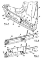
- the subassembly 4 comprises a frame 24 or chassis having a substantially planar shape, parallel to that of the window. To this frame is associated in the lower part of the subassembly 4 a liner 26 covering a face of the frame 24 directed towards the outside of the vehicle and visible to the figure 4 .
- the frame comprises in the lower rear portion, that is to say in its lower rear corner, a recess 28 for housing a motor 30 affixed against the inner face of the frame as shown in FIG. figure 5 .
- the frame 24 is generally of "C" shape. It has no leading edge so that a front edge of the subassembly is formed by the seal 22 of the glass.
- the frame has longitudinal upper and lower edges 32 substantially straight and parallel to each other. Each of these edges is inclined so that its rear end extends lower than its front end.
- the frame has a rear outer edge 34 substantially straight and inclined to the vertical direction so that its upper end extends closer to the front of the vehicle than its lower end.
- the frame has upper 36 and lower 38 inner edges.
- the edge 36 is substantially straight and parallel to the upper outer edge 30.
- the edge 38 is substantially straight but inclined with respect to the horizontal direction so that its forward end is lower than its rear end.
- the frame has a rear inner edge 40 substantially straight and inclined relative to the vertical so that its upper end extends further back than its lower end.
- the window 12 has upper, lower and rear edges whose shape corresponds substantially to the arrangement of the internal edges 36, 38 and 40 of the frame. The dimensions of the window are nevertheless greater than the internal perimeter of the frame.
- the frame carries the window 12 so that the latter is mounted to slide relative to the frame.
- the sliding direction 42 illustrated in FIG. figure 6 is parallel to the median longitudinal plane of the vehicle. It is inclined relative to the horizontal direction so that the level of the window lowers slightly as it slides towards the rear of the vehicle.
- the subset is configured so that the distance C, illustrated in FIG. figure 6 , between the most advanced position of the front edge 18 of the window marked by line 44 on the figure 6 and its most retracted position marked by the line 46 is 200 mm. As illustrated in figure 6 in its most remote position, the window protrudes from the frame to the rear.
- the subassembly comprises a lower window support 50 comprising a vertical plate 52 extending in the longitudinal direction of the vehicle. At its upper edge, the plate 52 carries a trough 54 having a "U" shape in cross section in which is received the lower edge of the pane 12 as illustrated in FIG. figure 10 .
- the trough is fixed to an inner face of the plate 52.
- the support 50 Projecting from the same face, the support 50 comprises ball joints 55 in this case two in number, received in spherical recesses of complementary shape formed in pads 56 having each has a general elongated rectangular parallelepipedal shape in the sliding direction 42.
- each pad 56 is received in a common rail 60 covering all of its upper and lower edges and its inner wall. It also covers part of its outer wall while nevertheless providing a light for the passage of the ball joints 55.
- the rail 60 is fixed by its inner face to the lower part of the frame lining 26 by means of several screws 28.
- the rail carries in the upper part a channel 62 with a circular section open laterally outward facing the plate 52.
- This channel receives a cable 64, one end of which is fixed to a catch 66 illustrated in FIGS. Figures 8 and 9 , itself rigidly fixed to the plate 52 at a light 68 of the latter.
- the cable extends throughout the portion of channel 62 between light 68 and the rear end of the channel, and then extends vertically to the engine.
- the latter has suitable drive means, known in themselves and not described in detail, for advancing and retreating the cable.
- On the side of the motor 30 opposite the part of the so-called active cable which has just been described extends the part of the cable called inactive or dead illustrated in particular to Figures 4 and 5 and referenced 70. This part is guided by means of reliefs 72 formed in the rear part of the frame.
- control of the motor 30 makes it possible to advance or retract the cable 64, which moves the plate 52 with the pads 56 along the lower rail 60 and drives the window.
- the frame comprises as longitudinal guiding means the movement of the window, in addition to the lower rail or slide 60, the upper rail or slide 74 fixed to the upper edge of the frame and accommodating the upper edge of the window 12.
- the subassembly comprises seals sealing against water and air between the inside and the outside of the vehicle when the window 12 is in the closed position, in particular at the level of the window 14 and the interface between the subassembly and the rest of the body.
- the subassembly comprises a seal 80 attached to the inner edge of the frame 24 and the liner 26, particularly where these edges are welded to each other.
- This seal forms an inner liner 82 coming into contact with an inner face of the pane 12 and, on the other side of the fixing edges, an inner liner 84.
- the vehicle comprises a seal 86 attached to the junction of the upper edges of a body wall, said quarter wall 88, and another said quarter lining 90.
- This seal comes into contact with an outer upper face of the wall 88 on one side of the fixing edge and on the other side comprises a lip 92 coming into contact with an outer face of the pane 12.
- the subassembly 4 further comprises a seal 94 attached to a lower edge of the frame, directed towards the outside of the vehicle and coming into contact with an inner face of the quarter panel lining 90. This seal ensures the sealing of the sub-assembly. partly internal.
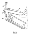
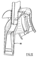
- the runoff collected by the liner 92 flows towards the lower front end of the window 12 and is collected by a collector 100 illustrated in particular in figures 11 and 12 , which returns this water towards the rear of the subassembly in the conduit formed by the underside of the frame 24, the quarter panel lining 90 and the lining 26. In the rear part, the water is finally discharged outside the vehicle by a pipe 102 visible to the figure 4 .
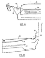
- the Figures 13 and 14 illustrate the two attachment drivers 104 and 106 for positioning the subassembly 4 when mounted on the vehicle.
- the driver 104 is attached to the front upper end of the frame extending in a direction generally perpendicular to the general plane of the frame. It is intended to be received in a notch formed on a rabbet 108 on the body side receiving the subassembly.
- the pilot 106 is provided substantially vertically to the driver 104 at the lower front end of the frame. It extends in a direction perpendicular to the median longitudinal plane of the vehicle. Attached to the frame 24 and to the frame lining 26, it is intended to penetrate into an opening of the quarter panel lining 90 or lower bridge.
- the subassembly 4 suitably positioned is also fixed rigidly to the vehicle by means of suitable fasteners, for example by means of screws which are in this case number 5.
- suitable fasteners for example by means of screws which are in this case number 5.
- the locations of three of these screws 110 have been illustrated on the figure 6 and are located on the upper edge of the frame for attachment to the body side. And the location most backward of these three has been illustrated in section at the figure 15 .
- the two other screw fixing locations 110 have been illustrated in FIGS. Figures 16 and 17 . They are located respectively at the lower ends of the front and rear of the subassembly. They allow its attachment here again to the quarterback lining 90.
- the assembly of the subassembly or module is carried out as follows.
- the subassembly is delivered on a chain with the window in a slightly retracted position, for example so that the distance d, illustrated in FIG. figure 6 , between the front edge of the glass and its most advanced position is 50 mm.
- the glass does not exceed the frame at the rear of it.
- This position of the window ajar for mounting avoids that the glass is damaged by the superstructure of the vehicle during assembly.
- the seal 22 intended to seal between the rear quarter glass pane 12 and the pane 14 of the rear door has already been fixed on the pane 12, for example by means of an adhesive.
- the seal 86 has been previously and separately mounted on the vehicle. The engine and mechanism are in place.
- the subassembly is presented from inside the vehicle.
- the slide or upper rail of the subassembly is brought near the upper rebate of the body side while indexing the subassembly by means of the upper driver 104 in the notch provided for this purpose on the same rabbet.
- This driver ensures at this stage a relative positioning of the subassembly relative to the vehicle in the X direction corresponding to the longitudinal direction of the vehicle.
- the other driver 106 is brought into the hole provided for this purpose on the quarter panel lining.
- the rotation is carried forward around the axis defined by the driver 104, that is to say an axis substantially perpendicular to the longitudinal direction of the vehicle.
- This pilot completes the positioning along the longitudinal direction X and the vertical direction Z.
- the subset is attached to vehicle with the five screws.
- the inner seal 80 which has been placed on hold on the frame is unwound in order to mount it in its housing and on the rear door rabbet.
- the evacuation pipe 102 is then introduced into the opening provided for this purpose on the body side. Furthermore, the motor and its control electronics carried by the frame 24 are connected to the control members of the vehicle.
- the module or subassembly according to the invention comprises a frame which integrates the rails or slides ensuring the longitudinal movement of the window.
- the frame also carries the engine with its management electronics preferably provided with an anti-pinch function.
- the subassembly or module comprises the seals ensuring the internal sealing of the vehicle as well as the rear seal of the rear door window. It further includes a system for channeling and outwardly draining interior and exterior water runoff into the environment of the quarter glass.
- the subassembly according to the invention can be mounted quickly on the vehicle and is a compact assembly incorporating a large part of the functions associated with the quarter window.
- the invention may be applied in the case where the vehicle has a single door on each side.
Landscapes
- Engineering & Computer Science (AREA)
- Mechanical Engineering (AREA)
- Window Of Vehicle (AREA)
- Seal Device For Vehicle (AREA)
- Body Structure For Vehicles (AREA)
- Glass Compositions (AREA)
Claims (10)
- Untereinheit (4) eines beweglichen hinteren Seitenfensters für ein Fahrzeug, die enthält:- eine Fensterscheibe (12); und- einen Motor (30),dadurch gekennzeichnet, dass sie einen die Fensterscheibe (12) und den Motor (30) tragenden Rahmen (24) enthält, wobei der Rahmen (24) Innenränder (36; 38; 40) aufweist, die so angeordnet sind, dass sie im Wesentlichen der Form des oberen, unteren und hinteren Rands der Fensterscheibe (12) entsprechen.
- Untereinheit (4) nach dem vorhergehenden Anspruch, dadurch gekennzeichnet, dass die Fensterscheibe (12) bezüglich des Rahmens (24) gleitbeweglich montiert ist.
- Untereinheit (4) nach einem der vorhergehenden Ansprüche, dadurch gekennzeichnet, dass der Rahmen (24) mindestens eine Führungsschiene (60, 74) für die Fensterscheibe (12) trägt.
- Untereinheit (4) nach einem der Ansprüche 2 und 3, dadurch gekennzeichnet, dass sie so gestaltet ist, dass die Fensterscheibe (12) in ihrer am weitesten zurückgeschobenen Stellung über ein hinteres Ende des Rahmens (24) bezüglich der Fahrrichtung des Fahrzeugs hinausgeht.
- Untereinheit (4) nach einem der vorhergehenden Ansprüche, dadurch gekennzeichnet, dass der Rahmen (24) mindestens eine Dichtung (80) trägt, die mit der Fensterscheibe in Kontakt sein kann.
- Untereinheit (4) nach einem der vorhergehenden Ansprüche, dadurch gekennzeichnet, dass die Fensterscheibe (12) einen eine Dichtung (22) tragenden vorderen Rand (18) aufweist.
- Untereinheit (4) nach einem der vorhergehenden Ansprüche, dadurch gekennzeichnet, dass sie Einrichtungen (24, 92, 100) zum Sammeln und Abführen von Wasser aufweist.
- Fahrzeug (2), das mindestens eine Untereinheit nach einem der vorhergehenden Ansprüche enthält, wobei das Fahrzeug eine Tür (8) enthält, die eine Fensterscheibe (14) trägt, welche keinen hinteren Steg aufweist und an das hintere Seitenfenster (12) angrenzt, wobei die Tür vorzugsweise eine hintere Tür ist.
- Verfahren zum Einbau eines hinteren Seitenfensters in ein Fahrzeug, dadurch gekennzeichnet, dass eine Untereinheit (4) nach einem der vorhergehenden Ansprüche in ein Fahrzeug (2) eingesetzt wird, wobei die Untereinheit (4) einen Rahmen (24) enthält, der eine Fensterscheibe (12) und einen Motor (30) trägt und Innenränder (36; 38; 40) aufweist, die so angeordnet sind, dass sie im Wesentlichen der Form des oberen, unteren und hinteren Rands der Fensterscheibe (12) entsprechen.
- Verfahren nach dem vorhergehenden Anspruch, dadurch gekennzeichnet, dass der Rahmen (24) mit der Fensterscheibe (12) in einer Stellung hinter ihrer bezüglich der Fahrrichtung des Fahrzeugs am weitesten vorne liegenden Stellung eingesetzt wird.
Applications Claiming Priority (1)
| Application Number | Priority Date | Filing Date | Title |
|---|---|---|---|
| FR0513242A FR2895318B1 (fr) | 2005-12-23 | 2005-12-23 | Sous-ensemble de vitre de custode mobile pour vehicule |
Publications (2)
| Publication Number | Publication Date |
|---|---|
| EP1800921A1 EP1800921A1 (de) | 2007-06-27 |
| EP1800921B1 true EP1800921B1 (de) | 2011-06-01 |
Family
ID=36950960
Family Applications (1)
| Application Number | Title | Priority Date | Filing Date |
|---|---|---|---|
| EP06301283A Not-in-force EP1800921B1 (de) | 2005-12-23 | 2006-12-21 | Modul für ein seitliches hinteres Eckfenster eines Fahrzeuges |
Country Status (3)
| Country | Link |
|---|---|
| EP (1) | EP1800921B1 (de) |
| AT (1) | ATE511453T1 (de) |
| FR (1) | FR2895318B1 (de) |
Cited By (1)
| Publication number | Priority date | Publication date | Assignee | Title |
|---|---|---|---|---|
| EP3793847A1 (de) * | 2018-05-16 | 2021-03-24 | RENAULT s.a.s. | Bewegliche viertelfensteranordnung für ein kraftfahrzeug |
Families Citing this family (1)
| Publication number | Priority date | Publication date | Assignee | Title |
|---|---|---|---|---|
| FR2943953A1 (fr) * | 2009-04-02 | 2010-10-08 | Peugeot Citroen Automobiles Sa | Agencement d'une vitre coulissante dans une porte d'un vehicule automobile |
Family Cites Families (6)
| Publication number | Priority date | Publication date | Assignee | Title |
|---|---|---|---|---|
| FR2739811B1 (fr) * | 1995-10-17 | 1997-12-12 | Renault | Vitre de custode susceptible de coulisser longitudinalement |
| JP3758909B2 (ja) * | 1999-09-06 | 2006-03-22 | シロキ工業株式会社 | 自動車のドア |
| FR2818589B1 (fr) * | 2000-12-26 | 2003-07-04 | France Design | Dispositif d'escamotage des vitres laterales de custode d'un vehicule automobile |
| FR2821319B1 (fr) * | 2001-02-26 | 2003-07-04 | Plastic Omnium Cie | Piece de carrosserie de custode |
| FR2851757B1 (fr) * | 2003-02-28 | 2006-04-14 | Peugeot Citroen Automobiles Sa | Procede de montage d'un leve-vitre et d'une vitre associee sur une custode, et ensemble de custode correspondant |
| FR2856348B1 (fr) * | 2003-06-18 | 2005-09-09 | Hutchinson | Procede de fabrication d'un module d'etancheite d'une vitre fixe, et module ainsi obtenu |
-
2005
- 2005-12-23 FR FR0513242A patent/FR2895318B1/fr not_active Expired - Fee Related
-
2006
- 2006-12-21 EP EP06301283A patent/EP1800921B1/de not_active Not-in-force
- 2006-12-21 AT AT06301283T patent/ATE511453T1/de not_active IP Right Cessation
Cited By (1)
| Publication number | Priority date | Publication date | Assignee | Title |
|---|---|---|---|---|
| EP3793847A1 (de) * | 2018-05-16 | 2021-03-24 | RENAULT s.a.s. | Bewegliche viertelfensteranordnung für ein kraftfahrzeug |
Also Published As
| Publication number | Publication date |
|---|---|
| FR2895318A1 (fr) | 2007-06-29 |
| ATE511453T1 (de) | 2011-06-15 |
| FR2895318B1 (fr) | 2010-07-30 |
| EP1800921A1 (de) | 2007-06-27 |
Similar Documents
| Publication | Publication Date | Title |
|---|---|---|
| EP2277729B1 (de) | Vorrichtung zum Schliessen einer in die Karosserie eines Fahrzeugs eingelassenen Öffnung mit Ausgleichsmitteln, und entsprechendes Kraftfahrzeug | |
| FR3041905A1 (fr) | Dispositif vitre affleurant pour porte de vehicule, porte, vehicule automobile, procede de fabrication et dispositif d'etancheite correspondants. | |
| EP3582986B1 (de) | Vorrichtung zur bündigen verglasung für eine fahrzeugtür, tür, kraftfahrzeug und entsprechendes herstellungsverfahren sowie einstückdichtungsvorrichtung | |
| FR2947765A1 (fr) | Dispositif de toit ouvrant notamment pour vehicule automobile | |
| EP3356168B1 (de) | Flächenbündige verglaste vorrichtung für eine fahrzeugtür mit einer beweglichen platte, sowie entsprechende tür und kraftfahrzeug | |
| EP4426570B1 (de) | Glasvorrichtung für eine fahrzeugtür mit einer bündig montierten beweglichen platte und entsprechende tür | |
| EP2072735B1 (de) | Schliesseinrichtung für eine Öffnung eines Kraftfahrzeugs mit einem beweglichen Schiebepaneel und konzentrischen Gleitschienen, und zugehöriges Kraftfahrzeug | |
| FR3021254A1 (fr) | Dispositif vitre affleurant pour porte de vehicule a panneau mobile reglable, porte et vehicule automobile correspondants. | |
| EP4110634B1 (de) | Fahrzeug mit mindestens einem zweiteiligen fenster mit einem kippbaren teil und einer zwischen den beiden teilen angeordneten dichtung | |
| EP1800921A1 (de) | Modul für ein seitliches hinteres Eckfenster eines Fahrzeuges | |
| EP2694306B2 (de) | Glasdach mit verschiebbarer und schwenkbarer mobiler platte | |
| WO2022053619A1 (fr) | Dispositif d'obturation d'une baie ménagée dans la carrosserie d'un véhicule équipé d'un embout formant butée mécanique d'une navette coulissante, et véhicule correspondant | |
| EP4070976B1 (de) | Dichtungsvorrichtung für fahrzeugkarosserie, insbesondere für kraftfahrzeug ohne b-säule | |
| EP1612072A1 (de) | Fahrzeugtür, Konstruktionsaufbau, Scheibeneinheit, Verfahren zum Herstellen und korrespondierende Fahrzeuge | |
| WO2017157493A1 (fr) | Dispositif vitre affleurant pour porte de vehicule a panneau mobile a moyens de blocage en x, patin, porte et vehicule automobile correspondants | |
| EP3156576B1 (de) | Fensterhebervorrichtung für ein kraftfahrzeug, entsprechende kraftfahrzeugtür und entsprechendes montageverfahren | |
| EP4426571B1 (de) | Glasvorrichtung für eine fahrzeugtür mit einer bündig montierten beweglichen platte und entsprechende tür | |
| WO2018068873A1 (fr) | Dispositif lève-vitre pour un véhicule automobile, porte de véhicule automobile et procédé d'assemblage correspondants | |
| EP1323557B1 (de) | Schliesseinrichtung einer Fahrzeugöffnung mit einer rotatorisch beweglichen Scheibe und zugehörigem Fahrzeug | |
| WO2016008938A1 (fr) | Pavillon vitre a panneau mobile controle par des navettes | |
| EP1747927A2 (de) | Beschattugssystem für eine Öffnung innerhalb eines Fahrzeuges mit nicht parallelen Führungsschienen und dazugehöriges Fahrzeug | |
| FR2908693A1 (fr) | Structure de hayon de vehicule automobile et vehicule automobile comportant une telle structure. | |
| EP1477355B1 (de) | Autotür mit Schutztsmitteln des oberen Bereichs einer flachmontierten Scheibe, Erweiterung des Schutzes und Fahrzeug hierzu. | |
| FR2901740A1 (fr) | Dispositif d'obturation d'une baie menagee dans un vehicule automobile, a rails non paralleles et pions mobiles, et vehicule correspondant | |
| FR3156706A1 (fr) | Système d’étanchéité pour un véhicule automobile avec des portes antagonistes. |
Legal Events
| Date | Code | Title | Description |
|---|---|---|---|
| PUAI | Public reference made under article 153(3) epc to a published international application that has entered the european phase |
Free format text: ORIGINAL CODE: 0009012 |
|
| AK | Designated contracting states |
Kind code of ref document: A1 Designated state(s): AT BE BG CH CY CZ DE DK EE ES FI FR GB GR HU IE IS IT LI LT LU LV MC NL PL PT RO SE SI SK TR |
|
| AX | Request for extension of the european patent |
Extension state: AL BA HR MK YU |
|
| 17P | Request for examination filed |
Effective date: 20071227 |
|
| 17Q | First examination report despatched |
Effective date: 20080204 |
|
| AKX | Designation fees paid |
Designated state(s): AT BE BG CH CY CZ DE DK EE ES FI FR GB GR HU IE IS IT LI LT LU LV MC NL PL PT RO SE SI SK TR |
|
| GRAP | Despatch of communication of intention to grant a patent |
Free format text: ORIGINAL CODE: EPIDOSNIGR1 |
|
| RIN1 | Information on inventor provided before grant (corrected) |
Inventor name: HEWAK, GREGOR Inventor name: VILATTE, JEAN-RENE |
|
| GRAS | Grant fee paid |
Free format text: ORIGINAL CODE: EPIDOSNIGR3 |
|
| GRAA | (expected) grant |
Free format text: ORIGINAL CODE: 0009210 |
|
| AK | Designated contracting states |
Kind code of ref document: B1 Designated state(s): AT BE BG CH CY CZ DE DK EE ES FI FR GB GR HU IE IS IT LI LT LU LV MC NL PL PT RO SE SI SK TR |
|
| REG | Reference to a national code |
Ref country code: GB Ref legal event code: FG4D Free format text: NOT ENGLISH |
|
| REG | Reference to a national code |
Ref country code: CH Ref legal event code: EP |
|
| REG | Reference to a national code |
Ref country code: IE Ref legal event code: FG4D Free format text: LANGUAGE OF EP DOCUMENT: FRENCH |
|
| REG | Reference to a national code |
Ref country code: DE Ref legal event code: R096 Ref document number: 602006022263 Country of ref document: DE Effective date: 20110714 |
|
| REG | Reference to a national code |
Ref country code: NL Ref legal event code: VDEP Effective date: 20110601 |
|
| PG25 | Lapsed in a contracting state [announced via postgrant information from national office to epo] |
Ref country code: SE Free format text: LAPSE BECAUSE OF FAILURE TO SUBMIT A TRANSLATION OF THE DESCRIPTION OR TO PAY THE FEE WITHIN THE PRESCRIBED TIME-LIMIT Effective date: 20110601 Ref country code: LT Free format text: LAPSE BECAUSE OF FAILURE TO SUBMIT A TRANSLATION OF THE DESCRIPTION OR TO PAY THE FEE WITHIN THE PRESCRIBED TIME-LIMIT Effective date: 20110601 |
|
| PG25 | Lapsed in a contracting state [announced via postgrant information from national office to epo] |
Ref country code: AT Free format text: LAPSE BECAUSE OF FAILURE TO SUBMIT A TRANSLATION OF THE DESCRIPTION OR TO PAY THE FEE WITHIN THE PRESCRIBED TIME-LIMIT Effective date: 20110601 Ref country code: CY Free format text: LAPSE BECAUSE OF FAILURE TO SUBMIT A TRANSLATION OF THE DESCRIPTION OR TO PAY THE FEE WITHIN THE PRESCRIBED TIME-LIMIT Effective date: 20110601 Ref country code: ES Free format text: LAPSE BECAUSE OF FAILURE TO SUBMIT A TRANSLATION OF THE DESCRIPTION OR TO PAY THE FEE WITHIN THE PRESCRIBED TIME-LIMIT Effective date: 20110912 Ref country code: SI Free format text: LAPSE BECAUSE OF FAILURE TO SUBMIT A TRANSLATION OF THE DESCRIPTION OR TO PAY THE FEE WITHIN THE PRESCRIBED TIME-LIMIT Effective date: 20110601 Ref country code: FI Free format text: LAPSE BECAUSE OF FAILURE TO SUBMIT A TRANSLATION OF THE DESCRIPTION OR TO PAY THE FEE WITHIN THE PRESCRIBED TIME-LIMIT Effective date: 20110601 Ref country code: GR Free format text: LAPSE BECAUSE OF FAILURE TO SUBMIT A TRANSLATION OF THE DESCRIPTION OR TO PAY THE FEE WITHIN THE PRESCRIBED TIME-LIMIT Effective date: 20110902 Ref country code: LV Free format text: LAPSE BECAUSE OF FAILURE TO SUBMIT A TRANSLATION OF THE DESCRIPTION OR TO PAY THE FEE WITHIN THE PRESCRIBED TIME-LIMIT Effective date: 20110601 |
|
| REG | Reference to a national code |
Ref country code: IE Ref legal event code: FD4D |
|
| PG25 | Lapsed in a contracting state [announced via postgrant information from national office to epo] |
Ref country code: NL Free format text: LAPSE BECAUSE OF FAILURE TO SUBMIT A TRANSLATION OF THE DESCRIPTION OR TO PAY THE FEE WITHIN THE PRESCRIBED TIME-LIMIT Effective date: 20110601 |
|
| PG25 | Lapsed in a contracting state [announced via postgrant information from national office to epo] |
Ref country code: IS Free format text: LAPSE BECAUSE OF FAILURE TO SUBMIT A TRANSLATION OF THE DESCRIPTION OR TO PAY THE FEE WITHIN THE PRESCRIBED TIME-LIMIT Effective date: 20111001 Ref country code: EE Free format text: LAPSE BECAUSE OF FAILURE TO SUBMIT A TRANSLATION OF THE DESCRIPTION OR TO PAY THE FEE WITHIN THE PRESCRIBED TIME-LIMIT Effective date: 20110601 Ref country code: CZ Free format text: LAPSE BECAUSE OF FAILURE TO SUBMIT A TRANSLATION OF THE DESCRIPTION OR TO PAY THE FEE WITHIN THE PRESCRIBED TIME-LIMIT Effective date: 20110601 Ref country code: PT Free format text: LAPSE BECAUSE OF FAILURE TO SUBMIT A TRANSLATION OF THE DESCRIPTION OR TO PAY THE FEE WITHIN THE PRESCRIBED TIME-LIMIT Effective date: 20111003 Ref country code: IE Free format text: LAPSE BECAUSE OF FAILURE TO SUBMIT A TRANSLATION OF THE DESCRIPTION OR TO PAY THE FEE WITHIN THE PRESCRIBED TIME-LIMIT Effective date: 20110601 |
|
| PG25 | Lapsed in a contracting state [announced via postgrant information from national office to epo] |
Ref country code: SK Free format text: LAPSE BECAUSE OF FAILURE TO SUBMIT A TRANSLATION OF THE DESCRIPTION OR TO PAY THE FEE WITHIN THE PRESCRIBED TIME-LIMIT Effective date: 20110601 Ref country code: PL Free format text: LAPSE BECAUSE OF FAILURE TO SUBMIT A TRANSLATION OF THE DESCRIPTION OR TO PAY THE FEE WITHIN THE PRESCRIBED TIME-LIMIT Effective date: 20110601 Ref country code: RO Free format text: LAPSE BECAUSE OF FAILURE TO SUBMIT A TRANSLATION OF THE DESCRIPTION OR TO PAY THE FEE WITHIN THE PRESCRIBED TIME-LIMIT Effective date: 20110601 |
|
| PLBE | No opposition filed within time limit |
Free format text: ORIGINAL CODE: 0009261 |
|
| STAA | Information on the status of an ep patent application or granted ep patent |
Free format text: STATUS: NO OPPOSITION FILED WITHIN TIME LIMIT |
|
| 26N | No opposition filed |
Effective date: 20120302 |
|
| PG25 | Lapsed in a contracting state [announced via postgrant information from national office to epo] |
Ref country code: IT Free format text: LAPSE BECAUSE OF FAILURE TO SUBMIT A TRANSLATION OF THE DESCRIPTION OR TO PAY THE FEE WITHIN THE PRESCRIBED TIME-LIMIT Effective date: 20110601 |
|
| REG | Reference to a national code |
Ref country code: DE Ref legal event code: R097 Ref document number: 602006022263 Country of ref document: DE Effective date: 20120302 |
|
| PG25 | Lapsed in a contracting state [announced via postgrant information from national office to epo] |
Ref country code: DK Free format text: LAPSE BECAUSE OF FAILURE TO SUBMIT A TRANSLATION OF THE DESCRIPTION OR TO PAY THE FEE WITHIN THE PRESCRIBED TIME-LIMIT Effective date: 20110601 |
|
| BERE | Be: lapsed |
Owner name: RENAULT S.A.S. Effective date: 20111231 |
|
| PG25 | Lapsed in a contracting state [announced via postgrant information from national office to epo] |
Ref country code: MC Free format text: LAPSE BECAUSE OF NON-PAYMENT OF DUE FEES Effective date: 20111231 |
|
| REG | Reference to a national code |
Ref country code: CH Ref legal event code: PL |
|
| PG25 | Lapsed in a contracting state [announced via postgrant information from national office to epo] |
Ref country code: BE Free format text: LAPSE BECAUSE OF NON-PAYMENT OF DUE FEES Effective date: 20111231 Ref country code: LI Free format text: LAPSE BECAUSE OF NON-PAYMENT OF DUE FEES Effective date: 20111231 Ref country code: CH Free format text: LAPSE BECAUSE OF NON-PAYMENT OF DUE FEES Effective date: 20111231 |
|
| PG25 | Lapsed in a contracting state [announced via postgrant information from national office to epo] |
Ref country code: LU Free format text: LAPSE BECAUSE OF NON-PAYMENT OF DUE FEES Effective date: 20111221 |
|
| PG25 | Lapsed in a contracting state [announced via postgrant information from national office to epo] |
Ref country code: BG Free format text: LAPSE BECAUSE OF FAILURE TO SUBMIT A TRANSLATION OF THE DESCRIPTION OR TO PAY THE FEE WITHIN THE PRESCRIBED TIME-LIMIT Effective date: 20110901 |
|
| PG25 | Lapsed in a contracting state [announced via postgrant information from national office to epo] |
Ref country code: TR Free format text: LAPSE BECAUSE OF FAILURE TO SUBMIT A TRANSLATION OF THE DESCRIPTION OR TO PAY THE FEE WITHIN THE PRESCRIBED TIME-LIMIT Effective date: 20110601 |
|
| PG25 | Lapsed in a contracting state [announced via postgrant information from national office to epo] |
Ref country code: HU Free format text: LAPSE BECAUSE OF FAILURE TO SUBMIT A TRANSLATION OF THE DESCRIPTION OR TO PAY THE FEE WITHIN THE PRESCRIBED TIME-LIMIT Effective date: 20110601 |
|
| REG | Reference to a national code |
Ref country code: FR Ref legal event code: PLFP Year of fee payment: 10 |
|
| REG | Reference to a national code |
Ref country code: FR Ref legal event code: PLFP Year of fee payment: 11 |
|
| PGFP | Annual fee paid to national office [announced via postgrant information from national office to epo] |
Ref country code: GB Payment date: 20161222 Year of fee payment: 11 Ref country code: DE Payment date: 20161213 Year of fee payment: 11 |
|
| PGFP | Annual fee paid to national office [announced via postgrant information from national office to epo] |
Ref country code: FR Payment date: 20161222 Year of fee payment: 11 |
|
| REG | Reference to a national code |
Ref country code: DE Ref legal event code: R119 Ref document number: 602006022263 Country of ref document: DE |
|
| GBPC | Gb: european patent ceased through non-payment of renewal fee |
Effective date: 20171221 |
|
| REG | Reference to a national code |
Ref country code: FR Ref legal event code: ST Effective date: 20180831 |
|
| PG25 | Lapsed in a contracting state [announced via postgrant information from national office to epo] |
Ref country code: DE Free format text: LAPSE BECAUSE OF NON-PAYMENT OF DUE FEES Effective date: 20180703 Ref country code: FR Free format text: LAPSE BECAUSE OF NON-PAYMENT OF DUE FEES Effective date: 20180102 |
|
| PG25 | Lapsed in a contracting state [announced via postgrant information from national office to epo] |
Ref country code: GB Free format text: LAPSE BECAUSE OF NON-PAYMENT OF DUE FEES Effective date: 20171221 |