EP1800925A2 - Dispositif de protection en cas de choc latéral et porte de véhicule avec un tel dispositif - Google Patents
Dispositif de protection en cas de choc latéral et porte de véhicule avec un tel dispositif Download PDFInfo
- Publication number
- EP1800925A2 EP1800925A2 EP06024484A EP06024484A EP1800925A2 EP 1800925 A2 EP1800925 A2 EP 1800925A2 EP 06024484 A EP06024484 A EP 06024484A EP 06024484 A EP06024484 A EP 06024484A EP 1800925 A2 EP1800925 A2 EP 1800925A2
- Authority
- EP
- European Patent Office
- Prior art keywords
- fork
- side impact
- motor vehicle
- vehicle door
- impact beam
- Prior art date
- Legal status (The legal status is an assumption and is not a legal conclusion. Google has not performed a legal analysis and makes no representation as to the accuracy of the status listed.)
- Granted
Links
Images

Classifications
-
- B—PERFORMING OPERATIONS; TRANSPORTING
- B60—VEHICLES IN GENERAL
- B60J—WINDOWS, WINDSCREENS, NON-FIXED ROOFS, DOORS, OR SIMILAR DEVICES FOR VEHICLES; REMOVABLE EXTERNAL PROTECTIVE COVERINGS SPECIALLY ADAPTED FOR VEHICLES
- B60J5/00—Doors
- B60J5/04—Doors arranged at the vehicle sides
- B60J5/042—Reinforcement elements
- B60J5/0422—Elongated type elements, e.g. beams, cables, belts or wires
- B60J5/0437—Elongated type elements, e.g. beams, cables, belts or wires characterised by the attachment means to the door, e.g. releasable attachment means
Definitions
- the side impact protection device comprises a side impact beam and a fastening device with which the side impact beam can be connected to a door part of the motor vehicle door.
- the fastening device has a mounting bracket, which is designed as a light metal casting and connected to the door part.
- the mounting bracket has a fork-shaped receptacle into which the side impact beam is inserted. The bifurcated receptacle and the side impact beam are penetrated by a retaining bolt, whereby the side impact beam is held on the receptacle.
- the fork-shaped receptacle has two inner surfaces facing the side impact member and spaced apart from each other and a forked bottom, so that the receptacle is approximately U-shaped.
- the opposing inner surfaces parallel to each other. Accordingly, the side impact beams in the box-shaped or rectangular cross-section.
- the invention has for its object to provide a motor vehicle door with a side impact protection device, wherein the fastening device can be easily made.
- the mounting bracket which is designed as a casting
- the fork-shaped receptacle widens in its direction away from the fork base direction.
- a core of the mold can thus be easily pulled out of the fork-shaped receptacle.
- the simple production of the fastening device also results from the fact that the inner surfaces of the fork-shaped exception exist as unprocessed casting surfaces. Unprocessed inner surfaces or cast surfaces are in the course of this application surfaces on the casting, which were not subjected to machining.
- the notch effect in the fork-shaped receptacle is reduced, wherein such a notch effect is in many cases produced by cutting, sharp tools in that sharp-edged corner regions or cuts are made in the casting skin. It has also been found to be particularly advantageous that the side impact beam with its matching in the fork-shaped receptacle cross-section over the known from the prior art rectangular or box-shaped profiles can provide an optimized side impact protection.
- development of the invention is advantageous that can be avoided by a loose side impact carrier by the play-free holding the side impact carrier within the fork-shaped receptacle during operation of the motor vehicle rattling.
- a particularly preferred embodiment is specified in claim 4.
- the advantage here is that the fork bridge with a reduced compared to the other fork material thickness can be applied to the side impact beams, whereby the initially mentioned play-free holding the side impact carrier in the recording can be advantageously achieved as the thinner of the two fork webs towards side impact beams can create.
- the retaining bolt is formed by a screw with a screw head.
- the retaining bolt is advantageously determined only in the fork web, which has the greater material thickness.
- the other fork bridge is only freely penetrated by the retaining bolt.
- a specified in claim 7 development of the invention has the advantage that the side impact beam can be easily inserted into the door inner part when the outer panel is not yet connected to the door inner part.
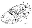
- Fig. 1 shows a motor vehicle 1, which has a body 2 with a side wall 3, in which a door opening 4 is introduced, in which a motor vehicle door 5 is movably inserted.
- the motor vehicle door which is referred to below only as a door 5, below a belt line 6 has a hollow door body 7, in which a present above the belt line 6 in its closed position window 8 in a lowered position (not shown) is displaced.
- a side impact protection device 9 is also fixedly inserted, which comprises an approximately parallel to the vehicle longitudinal axis FL side impact beam 10 and a fastening device 11 shown in FIGS. 2 and 3, via which the side impact beam 10 is connected to the door body 7.
- the side impact beam has a front end portion 13 adjacent to the A pillar 12 and a rear end portion 15 adjacent the B pillar 14.
- About the fastening device 11 of the front and rear end portion 13 and 15 of the side impact beam 10 are connected to the door body 7.
- a front mounting bracket 16 of the fastening device 11 is shown in a sectional view through the door body 7.
- a rear mounting bracket 17 of the fastening device 11 can be seen.
- the side impact beam 10 thus extends between the two mounting brackets 16 and 17.
- the door body 7 of the door 5 is preferably composed of at least two door parts 18 and 19, of which the door part 18 designed as a so-called door inner part 20 and the door part 19 of an outer panel 21st is formed, which is connected in an edge region 22 of the door 5 with the door inner part 20.
- the door inner part 20 is preferably made in one piece as a light metal casting and has a plurality of frame legs, of which an upright frame leg 22 adjacent to the A-pillar 12, another upright frame leg 23 adjacent to the B-pillar 15 and a lower frame leg, which is not shown , adjacent to a side sill 24 (see Fig. 1) and extending parallel thereto. Furthermore, an unillustrated, the two upright frame legs 22 and 23 connecting upper frame legs may be provided which extends parallel and below the waistline 6, so that the door inner part 20 may also be referred to as a peripheral frame.
- Each of the mounting brackets 16 and 17 is designed as a light metal casting and preferably made in one piece with the door part 18 and door inner part 20.
- the front attachment bracket 16 is connected to the door inner part 20 via a base portion 25.
- the rear mounting bracket 17 is directly, so without base 25, from the door inner part 20.
- the mounting brackets 16 and 17 have in common in each case a fork-shaped receptacle 26 with a freestanding upper fork web 27 and a lower freestanding fork web 28, which are connected to each other via an inner fork base 29.
- the free ends 30 and 31 of the fork webs 27 and 28 terminate adjacent to the door outer panel 21.
- the fork webs 27 and 28 take between the side impact beams 10 almost free of play.
- inner surfaces 32 and 33 of the fork-shaped receptacle 26 are aligned such that the fork-shaped receptacle 26 - starting from the fork base 29 - in the direction of the outer door panel 21, ie in a direction away from the fork base 29 34 direction.
- the inner surfaces 32 and 33, which face each other at a distance AB, are designed as unprocessed casting surfaces. Since the fork-shaped receptacle 26 expands in the direction of the door outer panel 21, the distance AB - starting from the fork base 29 - preferably increases continuously or continuously in the direction of the free ends 30 and 31 of the fork webs 27 and 28.
- the side impact beam 10 is trapezoidal in cross section and thus adapted to the widening receptacle 26.
- the side impact beam 10 is designed as a hollow profile and has by definition a compression belt 35 and a tension belt 36.
- the pressure belt 35 is adjacent to the outer door panel 21 and the Glasgurt 36 is close to the fork base 29.
- the two straps 35 and 36 are connected via an upper support wall 37 and a lower support wall 38.
- the height is HO the tension belt 36 is less than the height HO of the pressure belt 35 and the support walls 37 and 38 are parallel to the inner surfaces 32 and 33 of the fork-shaped receptacle 26.
- the side impact beam 10 is held without play within the receptacle 26 between the inner surfaces 32 and 33.
- the fork-shaped receptacle 26 is slightly clamped together by means of a holding bolt 39 penetrating the receptacle 26 and the side impact carrier 10, that is, the side impact carrier 10 is held between the fork webs 27 and 28.
- the retaining bolt 39 is preferably designed as a screw with a screw head 40 and a screw shank 41.
- the screw shaft 41 penetrates one of the fork webs 26 or 27 freely and is in the other fork web 28th or 27, for example, set by a thread.
- the lower fork web 28 has a thread into which the screw shank 41 is screwed.
- the upper fork web 27 is penetrated by the screw shaft 41 free.
- one of the two fork webs is also designed with a material thickness MS, which is less than the material thickness MS of the other fork web.
- the upper fork web 27 is provided with a lower material thickness MS than the lower fork bridge 28. This makes it possible in a simple manner, when tightening the retaining bolt 39 to stretch the upper fork bridge in the direction of the side impact beam 10, whereby the play-free holding within the receptacle 26th can be favored. Due to the material thickness MS of the lower fork web 28, the thread formed therein may have sufficient length so that the retaining bolt 39 can be securely fixed.
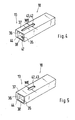
- FIGS. 4 and 5 an embodiment of a side impact beam 10 is shown in each case.
- the same or equivalent parts as in the other figures are provided with the same reference numerals.
- Figs. 4 and 5 only the front end portion 13 of the side impact member 10 is shown.
- an opening 42 is formed in both the upper and in the lower support wall 37 and 38, which is designed as extending in the vehicle longitudinal direction FL slot 43.
- the two exemplary embodiments illustrated in FIGS. 4 and 5 differ in that the slot 43 in FIG. 4 reduces its width WE in the direction of the end 44 of the side impact carrier 10.
- the slot 43 is designed with a constant width WE.
Landscapes
- Engineering & Computer Science (AREA)
- Mechanical Engineering (AREA)
- Lock And Its Accessories (AREA)
- Body Structure For Vehicles (AREA)
Applications Claiming Priority (1)
| Application Number | Priority Date | Filing Date | Title |
|---|---|---|---|
| DE102005062299A DE102005062299A1 (de) | 2005-12-24 | 2005-12-24 | Kraftfahrzeugtür mit einer Seitenaufprallschutzeinrichtung |
Publications (3)
| Publication Number | Publication Date |
|---|---|
| EP1800925A2 true EP1800925A2 (fr) | 2007-06-27 |
| EP1800925A3 EP1800925A3 (fr) | 2009-08-05 |
| EP1800925B1 EP1800925B1 (fr) | 2010-10-27 |
Family
ID=37876954
Family Applications (1)
| Application Number | Title | Priority Date | Filing Date |
|---|---|---|---|
| EP06024484A Not-in-force EP1800925B1 (fr) | 2005-12-24 | 2006-11-25 | Dispositif de protection en cas de choc latéral et porte de véhicule avec un tel dispositif |
Country Status (4)
| Country | Link |
|---|---|
| US (1) | US7325862B2 (fr) |
| EP (1) | EP1800925B1 (fr) |
| JP (1) | JP2007168781A (fr) |
| DE (2) | DE102005062299A1 (fr) |
Families Citing this family (5)
| Publication number | Priority date | Publication date | Assignee | Title |
|---|---|---|---|---|
| JP4388340B2 (ja) * | 2003-10-03 | 2009-12-24 | 新日本製鐵株式会社 | 自動車用強度部材 |
| JP5654045B2 (ja) * | 2010-12-13 | 2015-01-14 | 本田技研工業株式会社 | 車両の側部構造 |
| US8727421B2 (en) | 2011-08-31 | 2014-05-20 | Shape Corp. | Door beam assembly with roll formed beam |
| KR101338775B1 (ko) * | 2011-12-07 | 2013-12-06 | 현대자동차주식회사 | 2도어 차량의 도어 임팩트빔 유닛 |
| DE102015112499A1 (de) * | 2015-07-30 | 2017-02-02 | Dr. Ing. H.C. F. Porsche Aktiengesellschaft | Türaufprallträger |
Citations (3)
| Publication number | Priority date | Publication date | Assignee | Title |
|---|---|---|---|---|
| JPH05319092A (ja) | 1992-05-20 | 1993-12-03 | Mazda Motor Corp | 自動車のドアインパクトバー構造 |
| DE9218388U1 (de) | 1992-10-31 | 1994-02-24 | Julius & August Erbslöh GmbH & Co, 42553 Velbert | Türaufprallträger für Kraftwagenkarosserien |
| DE10320971B3 (de) | 2003-05-09 | 2004-09-16 | Dr.Ing.H.C. F. Porsche Ag | Seitenaufprallschutzeinrichtung sowie Kraftfahrzeugtür mit einer Seitenaufprallschutzeinrichtung |
Family Cites Families (6)
| Publication number | Priority date | Publication date | Assignee | Title |
|---|---|---|---|---|
| DE9207615U1 (de) * | 1992-06-02 | 1992-08-27 | Mannesmann AG, 4000 Düsseldorf | Einbauvorrichtung zum Fixieren eines Seitenaufprallträgers in einer Kraftfahrzeugtür |
| DE9215014U1 (de) * | 1992-11-04 | 1992-12-24 | Julius & August Erbslöh GmbH & Co, 5620 Velbert | Türaufprallträger für Kraftwagenkarosserien |
| DE19533366C2 (de) * | 1995-09-09 | 1998-03-19 | Ymos Ag Ind Produkte | Aufprallträger für Kraftfahrzeuge |
| US6020039A (en) * | 1998-04-21 | 2000-02-01 | Inland Steel Company | Automobile door impact beam |
| JP3588675B2 (ja) * | 2000-03-08 | 2004-11-17 | 日産自動車株式会社 | 車両用ドア構造 |
| JP2005035395A (ja) * | 2003-07-15 | 2005-02-10 | Nissan Motor Co Ltd | 車両用ドア構造 |
-
2005
- 2005-12-24 DE DE102005062299A patent/DE102005062299A1/de not_active Withdrawn
-
2006
- 2006-11-25 EP EP06024484A patent/EP1800925B1/fr not_active Not-in-force
- 2006-11-25 DE DE502006008176T patent/DE502006008176D1/de active Active
- 2006-12-20 JP JP2006342417A patent/JP2007168781A/ja not_active Withdrawn
- 2006-12-26 US US11/645,831 patent/US7325862B2/en active Active
Patent Citations (3)
| Publication number | Priority date | Publication date | Assignee | Title |
|---|---|---|---|---|
| JPH05319092A (ja) | 1992-05-20 | 1993-12-03 | Mazda Motor Corp | 自動車のドアインパクトバー構造 |
| DE9218388U1 (de) | 1992-10-31 | 1994-02-24 | Julius & August Erbslöh GmbH & Co, 42553 Velbert | Türaufprallträger für Kraftwagenkarosserien |
| DE10320971B3 (de) | 2003-05-09 | 2004-09-16 | Dr.Ing.H.C. F. Porsche Ag | Seitenaufprallschutzeinrichtung sowie Kraftfahrzeugtür mit einer Seitenaufprallschutzeinrichtung |
Also Published As
| Publication number | Publication date |
|---|---|
| DE102005062299A1 (de) | 2007-06-28 |
| US20070145772A1 (en) | 2007-06-28 |
| JP2007168781A (ja) | 2007-07-05 |
| DE502006008176D1 (de) | 2010-12-09 |
| US7325862B2 (en) | 2008-02-05 |
| EP1800925A3 (fr) | 2009-08-05 |
| EP1800925B1 (fr) | 2010-10-27 |
Similar Documents
| Publication | Publication Date | Title |
|---|---|---|
| DE102021202560B4 (de) | Hebel für einen Fahrzeugsitz | |
| EP1697596B1 (fr) | Evier | |
| EP3238569B1 (fr) | Dispositif de pose d'une paroi arrière sur un élément de meuble mobile | |
| EP0903265B1 (fr) | Dispositif absorbeur d'énergie pour un véhicule | |
| EP1939053A2 (fr) | Agencement de fixation, en particulier pour fixer une ferrure de déviation pour une section de sangle d'une ceinture de sécurité dans un véhicule, ainsi que procédé de fixation d'une ferrure de déviation sur une paroi porteuse | |
| EP1800925B1 (fr) | Dispositif de protection en cas de choc latéral et porte de véhicule avec un tel dispositif | |
| DE102017107055A1 (de) | Gleitverbindungsapplikation | |
| EP1501698B1 (fr) | Glissiere longitudinale a rails pour un siege de vehicule automobile | |
| DE10210781B4 (de) | Befestigungsmittel für einen Sicherheitsgurt | |
| EP1577032B1 (fr) | Guide-fil pour une machine à traiter des fils, en particulier une machine pour la fabrication de ressorts | |
| EP1475261A2 (fr) | Dispositif de protection en cas de choc latéral et porte de véhicule avec un tel dispositif | |
| DE10214862C5 (de) | Hardtop für ein Cabriolet-Fahrzeug | |
| EP3973818A1 (fr) | Paroi latérale de tiroir | |
| DE202011108692U1 (de) | Hohlprofil und Hallengerüst mit einem solchen Profil | |
| AT413583B (de) | Stabilisierungsvorrichtung für möbelteile | |
| DE10009675B4 (de) | Seitenaufprallschutz | |
| EP0291973B1 (fr) | Pièce de jonction de deux barres profilées aboutissant angulairement pour cadres de fenêtre ou porte | |
| DE19753885B4 (de) | Türrahmen mit einem Schließbolzen | |
| EP2099989A2 (fr) | Crémone | |
| DE102018208800B4 (de) | Verbindungsanordnung mit einem Dachprofil und einem Dachgepäckträger | |
| DE10143939A1 (de) | Schließeinrichtung für ein Kraftfahrzeug | |
| DE60026814T2 (de) | Rollo mit vorgespanntem Gehäuse und korrespondierendes Montageverfahren | |
| DE102004028307B4 (de) | Halteranordnung, insbesondere zur Halterung von Zusatzaggregaten, wie Heizgerät, an einem Fahrzeug | |
| EP1445409B1 (fr) | Elément de support et réception pour charnières | |
| DE19923434B4 (de) | Vorrichtung zur Befestigung einer Beschlagleiste an einem Profil |
Legal Events
| Date | Code | Title | Description |
|---|---|---|---|
| PUAI | Public reference made under article 153(3) epc to a published international application that has entered the european phase |
Free format text: ORIGINAL CODE: 0009012 |
|
| AK | Designated contracting states |
Kind code of ref document: A2 Designated state(s): AT BE BG CH CY CZ DE DK EE ES FI FR GB GR HU IE IS IT LI LT LU LV MC NL PL PT RO SE SI SK TR |
|
| AX | Request for extension of the european patent |
Extension state: AL BA HR MK YU |
|
| RAP1 | Party data changed (applicant data changed or rights of an application transferred) |
Owner name: DR. ING. H.C. F. PORSCHE AKTIENGESELLSCHAFT |
|
| RAP1 | Party data changed (applicant data changed or rights of an application transferred) |
Owner name: DR. ING. H.C. F. PORSCHE AKTIENGESELLSCHAFT |
|
| PUAL | Search report despatched |
Free format text: ORIGINAL CODE: 0009013 |
|
| AK | Designated contracting states |
Kind code of ref document: A3 Designated state(s): AT BE BG CH CY CZ DE DK EE ES FI FR GB GR HU IE IS IT LI LT LU LV MC NL PL PT RO SE SI SK TR |
|
| AX | Request for extension of the european patent |
Extension state: AL BA HR MK RS |
|
| 17P | Request for examination filed |
Effective date: 20100205 |
|
| 17Q | First examination report despatched |
Effective date: 20100301 |
|
| RAP1 | Party data changed (applicant data changed or rights of an application transferred) |
Owner name: DR. ING. H.C. F. PORSCHE AG |
|
| AKX | Designation fees paid |
Designated state(s): DE FR GB IT |
|
| GRAP | Despatch of communication of intention to grant a patent |
Free format text: ORIGINAL CODE: EPIDOSNIGR1 |
|
| GRAS | Grant fee paid |
Free format text: ORIGINAL CODE: EPIDOSNIGR3 |
|
| GRAA | (expected) grant |
Free format text: ORIGINAL CODE: 0009210 |
|
| AK | Designated contracting states |
Kind code of ref document: B1 Designated state(s): DE FR GB IT |
|
| REG | Reference to a national code |
Ref country code: GB Ref legal event code: FG4D Free format text: NOT ENGLISH |
|
| REF | Corresponds to: |
Ref document number: 502006008176 Country of ref document: DE Date of ref document: 20101209 Kind code of ref document: P |
|
| PGFP | Annual fee paid to national office [announced via postgrant information from national office to epo] |
Ref country code: FR Payment date: 20101130 Year of fee payment: 5 |
|
| PGFP | Annual fee paid to national office [announced via postgrant information from national office to epo] |
Ref country code: GB Payment date: 20101118 Year of fee payment: 5 |
|
| PGFP | Annual fee paid to national office [announced via postgrant information from national office to epo] |
Ref country code: IT Payment date: 20101125 Year of fee payment: 5 |
|
| PLBE | No opposition filed within time limit |
Free format text: ORIGINAL CODE: 0009261 |
|
| STAA | Information on the status of an ep patent application or granted ep patent |
Free format text: STATUS: NO OPPOSITION FILED WITHIN TIME LIMIT |
|
| 26N | No opposition filed |
Effective date: 20110728 |
|
| REG | Reference to a national code |
Ref country code: DE Ref legal event code: R097 Ref document number: 502006008176 Country of ref document: DE Effective date: 20110728 |
|
| GBPC | Gb: european patent ceased through non-payment of renewal fee |
Effective date: 20111125 |
|
| REG | Reference to a national code |
Ref country code: FR Ref legal event code: ST Effective date: 20120731 |
|
| PG25 | Lapsed in a contracting state [announced via postgrant information from national office to epo] |
Ref country code: IT Free format text: LAPSE BECAUSE OF NON-PAYMENT OF DUE FEES Effective date: 20111125 |
|
| PG25 | Lapsed in a contracting state [announced via postgrant information from national office to epo] |
Ref country code: GB Free format text: LAPSE BECAUSE OF NON-PAYMENT OF DUE FEES Effective date: 20111125 |
|
| PG25 | Lapsed in a contracting state [announced via postgrant information from national office to epo] |
Ref country code: FR Free format text: LAPSE BECAUSE OF NON-PAYMENT OF DUE FEES Effective date: 20111130 |
|
| PGFP | Annual fee paid to national office [announced via postgrant information from national office to epo] |
Ref country code: DE Payment date: 20151109 Year of fee payment: 10 |
|
| REG | Reference to a national code |
Ref country code: DE Ref legal event code: R119 Ref document number: 502006008176 Country of ref document: DE |
|
| PG25 | Lapsed in a contracting state [announced via postgrant information from national office to epo] |
Ref country code: DE Free format text: LAPSE BECAUSE OF NON-PAYMENT OF DUE FEES Effective date: 20170601 |