EP1800968A2 - Dispositif à coussin gonflable, avec agrafe facilitant le montage-démontage - Google Patents
Dispositif à coussin gonflable, avec agrafe facilitant le montage-démontage Download PDFInfo
- Publication number
- EP1800968A2 EP1800968A2 EP06025113A EP06025113A EP1800968A2 EP 1800968 A2 EP1800968 A2 EP 1800968A2 EP 06025113 A EP06025113 A EP 06025113A EP 06025113 A EP06025113 A EP 06025113A EP 1800968 A2 EP1800968 A2 EP 1800968A2
- Authority
- EP
- European Patent Office
- Prior art keywords
- latching
- control element
- gas bag
- bag module
- locked state
- Prior art date
- Legal status (The legal status is an assumption and is not a legal conclusion. Google has not performed a legal analysis and makes no representation as to the accuracy of the status listed.)
- Granted
Links
Images
Classifications
-
- B—PERFORMING OPERATIONS; TRANSPORTING
- B60—VEHICLES IN GENERAL
- B60R—VEHICLES, VEHICLE FITTINGS, OR VEHICLE PARTS, NOT OTHERWISE PROVIDED FOR
- B60R21/00—Arrangements or fittings on vehicles for protecting or preventing injuries to occupants or pedestrians in case of accidents or other traffic risks
- B60R21/02—Occupant safety arrangements or fittings, e.g. crash pads
- B60R21/16—Inflatable occupant restraints or confinements designed to inflate upon impact or impending impact, e.g. air bags
- B60R21/20—Arrangements for storing inflatable members in their non-use or deflated condition; Arrangement or mounting of air bag modules or components
-
- B—PERFORMING OPERATIONS; TRANSPORTING
- B60—VEHICLES IN GENERAL
- B60R—VEHICLES, VEHICLE FITTINGS, OR VEHICLE PARTS, NOT OTHERWISE PROVIDED FOR
- B60R21/00—Arrangements or fittings on vehicles for protecting or preventing injuries to occupants or pedestrians in case of accidents or other traffic risks
- B60R21/02—Occupant safety arrangements or fittings, e.g. crash pads
- B60R21/16—Inflatable occupant restraints or confinements designed to inflate upon impact or impending impact, e.g. air bags
- B60R21/20—Arrangements for storing inflatable members in their non-use or deflated condition; Arrangement or mounting of air bag modules or components
- B60R21/203—Arrangements for storing inflatable members in their non-use or deflated condition; Arrangement or mounting of air bag modules or components in steering wheels or steering columns
- B60R21/2035—Arrangements for storing inflatable members in their non-use or deflated condition; Arrangement or mounting of air bag modules or components in steering wheels or steering columns using modules containing inflator, bag and cover attachable to the steering wheel as a complete sub-unit
Definitions
- the invention relates to an assembly with an airbag module and a locking control device, with a first latching element, which is designed for engagement in a second latching element for forming a latching connection for fastening the airbag module to a vehicle-fixed component, wherein the airbag module can assume an incorrectly locked state, in that the first detent element and the second detent element are in contact with each other but are not in correct engagement, and a correctly locked state in which the first detent element is in engagement with the second detent element.
- Gas bag modules are now part of the standard equipment of passenger cars. Therefore, their assembly should of course be done quickly and inexpensively without sacrificing safety.
- offer latching connections in which, for example, connected to the gas bag module latching hooks engage in a complementary locking element on a vehicle-fixed component, such as a spring wire to connect the gas bag module firmly and load-bearing with the vehicle.
- a locking connection can be produced very time-saving.
- latching connections of this type an incorrectly locked state could occur in which the latching elements are already in contact with each other, but the latching hook has not yet engaged behind the spring wire correctly. Since the locking mechanism is usually not visible from the outside, such false locks are difficult to see.
- the invention provides for an assembly mentioned above, that the locking control device comprises a movably arranged control element, and a portion of the control element in the incorrectly locked state of the airbag module assumes a first position and occupies a second position in the correctly locked state of the airbag module and the control element in the first position in the assembled state and seen from the outside, a first indicator position and in the second position occupies a second indicator position different from the first indicator position and forms an indication for a not correctly locked state located in the airbag module.
- the control element can be from the outside, for example from the outside of a trim part, behind which the latching connection is arranged, for. visually recognize or feel. In this way, the state of the locking connection can be checked without direct access to this. Thus, it is clear that in the presence or absence of the control element at a certain point, the locking connection is not correctly locked.
- the control element may e.g. only in the first or in the second position do you push out a portion of a trim panel, e.g. bulge.
- the control element projects alternatively only in the first or only in the second position through an opening in a trim part.
- control element is formed by a portion of the second latching element. Alternatively, it may be formed by a separate, coupled to the second locking element component.
- the second latching element is preferably arranged displaceably.
- the position of the control element is changed by the movement of the second latching element.
- the second locking element may be, for example, a spring wire or a more or less rigid plate, which is then preferably acted upon elastically.
- the second latching element is first deflected by the first latching element before the actual latching engagement takes place. In the incorrectly locked state, the deflection of the second locking element remains. According to the invention, this deflection of the second latching element is utilized in order to provide an indication of an incorrectly closed latching connection and thus of a gas bag module not in the correctly locked state.
- Such a control can be found e.g. For gas bag modules, which are used in a steering wheel.
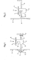
- FIG. 1 shows an assembly with an airbag module 10. It is shown a latching connection between an airbag module 10 and a vehicle-mounted component 11.
- the airbag module 10 is only by one of its first locking elements 12, here a latching hook, and a base plate 14 connected thereto, e.g. a generator support, a not shown, known module housing indicated.
- the module housing contains a folded gas bag (not shown) as well as a gas generator (also not shown) that provides inflation gas for inflating the gas bag.
- the vehicle-mounted component 11 is shown only schematically. Here it can be e.g. to act a hub of a steering wheel, a mounting plate in front of the steering wheel hub or a portion of an instrument panel. These are all familiar elements that will not be discussed here.
- a second locking element 16 is attached on the vehicle-fixed component 11.
- the second latching element 16 in this case a spring wire, has at least one elastically deflectable or displaceably arranged section which is temporarily moved sideways during the production of a latching connection between the first latching element 12 and the second latching element 16 and finally with a latching recess 18 of the first latching element 12 engages.
- the second latching element 16 may also be a rigid plate which is displaceable in the lateral direction by means of a spring (not shown).
- Other forms of the second locking element 16, in which a portion of the second locking element 16 is deflectable can be used here.
- the airbag module 10 is moved toward the second latching element 16 in the z-direction.
- a run-on slope 20 of the first locking element 12 in contact with the displaceable portion of the second locking element 16 and moves it to the side (to the left in Fig. 1, see arrow).
- a locking control device with a control element 22 is provided in the assembly.
- the control element 22 is formed by a part of the second latching element 16, in this case the section projecting furthest to the left.
- the control element 22 follows the lateral movement of the second detent element 16. If the gas bag module 10 is in the incorrectly locked state, the control element 22 is in a first position (shown in FIG. 1), namely deflected laterally to the left.
- the control element 22 does not have to be an integral part of the second detent element 16; it could also be a separate component 22 'coupled thereto (indicated by the dotted line in the figures).
- the control element 22 is arranged so that it bulges out a portion 23 of a trim part 24 at its maximum deflection shown in Figure 1.
- control element 22 can also project through an opening 26 in the trim part 24 (shown in dashed lines in FIG. 1).
- the control element 22 pushes the cowling 24 outwardly or protrudes through the opening 26 in the cowling 24.
- the control element 22 In the assembled state and from the outside (eg from outside the cowling 24), ie seen from the vehicle interior, the control element 22 is now in a first indicator position indicating a locking state of the latching connection. In this case it shows in the first indicator position through the Buckling of the lining part 24 or through the protruding through the opening 26 portion of the control element 22 that the airbag module 10 is in the incorrectly locked state.
- the elastic covering part 24 By the elastic covering part 24, the restoring force for the second locking element 16 can be supported or generated completely.
- the trim part 24 is e.g. the outer panel of a hub pot of a steering wheel or the outer panel of a dashboard or a part of an outer skin of a seat back.
- the portion 23 of the trim piece 24 is externally, i. from outside the panel from the vehicle interior, visible or tactile.
- control element 22 In the assembled state and from the outside, i. seen from the vehicle interior, the control element 22 is now in a second indicator position indicating a locking state of the latching connection, in this case that the gas bag module 10 is in the correctly locked state.
- control element 22 could also be designed and arranged such that the situation is reversed: then, in the correctly locked condition (which corresponds to the second indicator position), the control element 22 or component 22 'would bulge the trim panel 24 or protrude through the opening 26 while in the incorrectly locked state (which corresponds to the first indicator position), the control element 22 or the component 22 'would not be palpable or invisible.
- the second indicator position is different from the first one.
- control element 22 It would also be conceivable to make the control element 22 removable. Here it makes sense to use a separate component 22 'as the control element 22 as described above. When the gas bag module 10 is locked correctly, the control element 22 is then in the first position, in which it projects through the opening 26 and can be removed from the gas bag module. Here it is, of course possible to provide a coding to later prove that this particular locking connection was properly locked.
- the trim part 24 is preferably made of flexible polyurethane.
- first latching element 12 could be displaceable or deflectable and the second latching element 16 fixedly arranged.
- control element 22 could be formed on the first latching element 12 or coupled thereto.
- both locking elements 12, 16 can be formed deflectable or displaceable. A vertical deflection of the first and second locking element 12, 16 would be exploitable.
- the second locking element 16 is shown arranged on the vehicle-fixed component 11, it is of course at the discretion of the skilled person to replace the locking elements 12, 16 and instead to arrange the second locking element 16 on the gas bag module 10.
Landscapes
- Engineering & Computer Science (AREA)
- Mechanical Engineering (AREA)
- Air Bags (AREA)
Applications Claiming Priority (1)
| Application Number | Priority Date | Filing Date | Title |
|---|---|---|---|
| DE202005019961U DE202005019961U1 (de) | 2005-12-21 | 2005-12-21 | Gassackmodul mit Verriegelungskontrolleinrichtung |
Publications (3)
| Publication Number | Publication Date |
|---|---|
| EP1800968A2 true EP1800968A2 (fr) | 2007-06-27 |
| EP1800968A3 EP1800968A3 (fr) | 2007-08-08 |
| EP1800968B1 EP1800968B1 (fr) | 2010-02-24 |
Family
ID=36274276
Family Applications (1)
| Application Number | Title | Priority Date | Filing Date |
|---|---|---|---|
| EP06025113A Not-in-force EP1800968B1 (fr) | 2005-12-21 | 2006-12-05 | Dispositif à coussin gonflable, avec agrafe facilitant le montage-démontage |
Country Status (3)
| Country | Link |
|---|---|
| US (1) | US7597344B2 (fr) |
| EP (1) | EP1800968B1 (fr) |
| DE (2) | DE202005019961U1 (fr) |
Families Citing this family (3)
| Publication number | Priority date | Publication date | Assignee | Title |
|---|---|---|---|---|
| DE102007056227A1 (de) * | 2007-11-22 | 2009-06-04 | Continental Automotive Gmbh | Airbag-Satellit |
| US9783147B2 (en) * | 2015-08-18 | 2017-10-10 | Key Safety Systems, Inc. | Driver air bag with snap-in attachment mechanism |
| DE102020117454A1 (de) | 2020-07-02 | 2022-01-05 | Bayerische Motoren Werke Aktiengesellschaft | Verfahren zur Überwachung einer wenigstens einen Clipkörper umfassenden Clipverbindung an einem Bauteil |
Family Cites Families (10)
| Publication number | Priority date | Publication date | Assignee | Title |
|---|---|---|---|---|
| US4974873A (en) * | 1987-02-26 | 1990-12-04 | Honda Giken Kogyo Kabushiki Kaisha | Malfunction preventing device for air bag module in automobiles |
| US5505483A (en) * | 1993-04-28 | 1996-04-09 | Nippondenso Co., Ltd. | Airbag safety module for vehicle |
| US5380037A (en) * | 1993-10-25 | 1995-01-10 | General Motors Corporation | Snap-in inflatable restraint module mounting mechanism including latch elements |
| DE19854335A1 (de) | 1998-11-25 | 2000-06-15 | Autoliv Dev | Clipsverbindung mit Verriegelungsabfrage |
| DE19927032A1 (de) * | 1999-06-04 | 2000-12-14 | Petri Ag | Anordnung zur Verrastung eines Airbagmoduls mit einem Lenkrad |
| DE20017527U1 (de) * | 2000-10-12 | 2001-02-22 | TRW Automotive Safety Systems GmbH & Co. KG, 63743 Aschaffenburg | Fahrzeuglenkrad |
| GB2383301A (en) * | 2001-12-18 | 2003-06-25 | Autoliv Dev | Air bag unit with locating means |
| DE20204461U1 (de) * | 2002-03-20 | 2002-07-25 | TRW Automotive Safety Systems GmbH & Co. KG, 63743 Aschaffenburg | Baugruppe mit Rastelementen |
| DE20219124U1 (de) * | 2002-12-10 | 2003-04-17 | TRW Automotive Safety Systems GmbH, 63743 Aschaffenburg | Kontrollsystem für Rastverbindungen |
| DE202005020078U1 (de) * | 2005-12-21 | 2006-02-16 | Trw Automotive Safety Systems Gmbh | Gassackmodul |
-
2005
- 2005-12-21 DE DE202005019961U patent/DE202005019961U1/de not_active Expired - Lifetime
-
2006
- 2006-12-05 DE DE502006006231T patent/DE502006006231D1/de active Active
- 2006-12-05 EP EP06025113A patent/EP1800968B1/fr not_active Not-in-force
- 2006-12-15 US US11/639,702 patent/US7597344B2/en active Active
Non-Patent Citations (1)
| Title |
|---|
| None |
Also Published As
| Publication number | Publication date |
|---|---|
| US20070138770A1 (en) | 2007-06-21 |
| US7597344B2 (en) | 2009-10-06 |
| EP1800968A3 (fr) | 2007-08-08 |
| EP1800968B1 (fr) | 2010-02-24 |
| DE202005019961U1 (de) | 2006-04-13 |
| DE502006006231D1 (de) | 2010-04-08 |
Similar Documents
| Publication | Publication Date | Title |
|---|---|---|
| DE102017117534A1 (de) | Sitzschienenmodul für einen Fahrzeugsitz zur Fahrzeugsitzverzögerung im Crashfall | |
| DE102008015188A1 (de) | Fahrzeugüberkopfkonsolenvorrichtung mit einer absenkbaren Fahrzeuginsassenspiegelvorrichtung | |
| DE102020133574A1 (de) | Sicherheitsgurtvorrichtung | |
| DE202021105623U1 (de) | Fahrzeugcockpit-Modulanordnung | |
| EP1800968B1 (fr) | Dispositif à coussin gonflable, avec agrafe facilitant le montage-démontage | |
| WO2018188885A1 (fr) | Module sac gonflable, volant de direction et procédé permettant de relier un module sac gonflable à un volant de direction | |
| DE102021111989A1 (de) | Gurtführungsvorrichtung für einen Passagierrückhaltegurt eines Kraftfahrzeugs | |
| DE102022119183B4 (de) | Kraftfahrzeugsitz mit einer beleuchtbaren Blende und Kraftfahrzeug mit einem solchen Kraftfahrzeugsitz | |
| DE102021105013A1 (de) | Lasttragender Gurtaufroller | |
| DE102017117272A1 (de) | Gurtstraffer für einen Sicherheitsgurt eines Fahrzeuges | |
| DE60102092T2 (de) | Schaltereinheit für ein Lenkrad in einem Kraftfahrzeug | |
| DE102013011811A1 (de) | Gassackbaugruppe und lenkradbaugruppe | |
| DE202006020577U1 (de) | Baugruppe mit einer Instrumententafel für Kraftfahrzeuge und einem Kniegassack | |
| EP1407945A2 (fr) | Capteur de position magnétique | |
| DE202011001896U1 (de) | Vorrichtung zur Sitzbelegungserfassung für Fahrzeugsitze | |
| DE202015001912U1 (de) | Sitzbelegungssensoreinheit und Sitz | |
| EP1350962B1 (fr) | Ensemble de modules à éléments d'encliquetage | |
| DE102011120490A1 (de) | Anordnung eines Lenkrades und eines mit diesem verbundenen Airbag-Moduls bei einem Kraftfahrzeug | |
| DE10307535A1 (de) | Baugruppe für eine Sicherheitsgurtanordnung | |
| EP0284723B1 (fr) | Antivol de direction pour automobile | |
| EP1800970B1 (fr) | Module de sac de sécurité gonflable | |
| DE60109116T2 (de) | Kraftfahrzeugausrüstung enthaltend verbesserte Befestigungs- und elektrische Verbindungsmittel | |
| DE102011050151A1 (de) | Anordnung für einen Verstellmechanismus im Kfz-Bereich sowie ein Verfahren zur Verstellung eines derartigen Verstellmechanismus | |
| DE202005020078U1 (de) | Gassackmodul | |
| DE102009007401B4 (de) | Gassackmodul mit Hupenkontakt |
Legal Events
| Date | Code | Title | Description |
|---|---|---|---|
| PUAI | Public reference made under article 153(3) epc to a published international application that has entered the european phase |
Free format text: ORIGINAL CODE: 0009012 |
|
| AK | Designated contracting states |
Kind code of ref document: A2 Designated state(s): AT BE BG CH CY CZ DE DK EE ES FI FR GB GR HU IE IS IT LI LT LU LV MC NL PL PT RO SE SI SK TR |
|
| AX | Request for extension of the european patent |
Extension state: AL BA HR MK YU |
|
| PUAL | Search report despatched |
Free format text: ORIGINAL CODE: 0009013 |
|
| AK | Designated contracting states |
Kind code of ref document: A3 Designated state(s): AT BE BG CH CY CZ DE DK EE ES FI FR GB GR HU IE IS IT LI LT LU LV MC NL PL PT RO SE SI SK TR |
|
| AX | Request for extension of the european patent |
Extension state: AL BA HR MK YU |
|
| 17P | Request for examination filed |
Effective date: 20080204 |
|
| AKX | Designation fees paid |
Designated state(s): DE ES FR IT |
|
| GRAP | Despatch of communication of intention to grant a patent |
Free format text: ORIGINAL CODE: EPIDOSNIGR1 |
|
| GRAS | Grant fee paid |
Free format text: ORIGINAL CODE: EPIDOSNIGR3 |
|
| GRAA | (expected) grant |
Free format text: ORIGINAL CODE: 0009210 |
|
| AK | Designated contracting states |
Kind code of ref document: B1 Designated state(s): DE ES FR IT |
|
| REF | Corresponds to: |
Ref document number: 502006006231 Country of ref document: DE Date of ref document: 20100408 Kind code of ref document: P |
|
| REG | Reference to a national code |
Ref country code: DE Ref legal event code: R096 Ref document number: 502006006231 Country of ref document: DE Effective date: 20100408 |
|
| PG25 | Lapsed in a contracting state [announced via postgrant information from national office to epo] |
Ref country code: ES Free format text: LAPSE BECAUSE OF FAILURE TO SUBMIT A TRANSLATION OF THE DESCRIPTION OR TO PAY THE FEE WITHIN THE PRESCRIBED TIME-LIMIT Effective date: 20100604 |
|
| PLBE | No opposition filed within time limit |
Free format text: ORIGINAL CODE: 0009261 |
|
| STAA | Information on the status of an ep patent application or granted ep patent |
Free format text: STATUS: NO OPPOSITION FILED WITHIN TIME LIMIT |
|
| 26N | No opposition filed |
Effective date: 20101125 |
|
| REG | Reference to a national code |
Ref country code: DE Ref legal event code: R097 Ref document number: 502006006231 Country of ref document: DE Effective date: 20101125 |
|
| PG25 | Lapsed in a contracting state [announced via postgrant information from national office to epo] |
Ref country code: IT Free format text: LAPSE BECAUSE OF FAILURE TO SUBMIT A TRANSLATION OF THE DESCRIPTION OR TO PAY THE FEE WITHIN THE PRESCRIBED TIME-LIMIT Effective date: 20100224 |
|
| PGFP | Annual fee paid to national office [announced via postgrant information from national office to epo] |
Ref country code: FR Payment date: 20120104 Year of fee payment: 6 |
|
| REG | Reference to a national code |
Ref country code: FR Ref legal event code: ST Effective date: 20130830 |
|
| PG25 | Lapsed in a contracting state [announced via postgrant information from national office to epo] |
Ref country code: FR Free format text: LAPSE BECAUSE OF NON-PAYMENT OF DUE FEES Effective date: 20130102 |
|
| REG | Reference to a national code |
Ref country code: DE Ref legal event code: R081 Ref document number: 502006006231 Country of ref document: DE Owner name: ZF AUTOMOTIVE SAFETY GERMANY GMBH, DE Free format text: FORMER OWNER: TRW AUTOMOTIVE SAFETY SYSTEMS GMBH, 63743 ASCHAFFENBURG, DE Ref country code: DE Ref legal event code: R082 Ref document number: 502006006231 Country of ref document: DE Representative=s name: MEHNERT, BERNHARD, DE |
|
| P01 | Opt-out of the competence of the unified patent court (upc) registered |
Effective date: 20230628 |
|
| PGFP | Annual fee paid to national office [announced via postgrant information from national office to epo] |
Ref country code: DE Payment date: 20231231 Year of fee payment: 18 |
|
| REG | Reference to a national code |
Ref country code: DE Ref legal event code: R119 Ref document number: 502006006231 Country of ref document: DE |
|
| PG25 | Lapsed in a contracting state [announced via postgrant information from national office to epo] |
Ref country code: DE Free format text: LAPSE BECAUSE OF NON-PAYMENT OF DUE FEES Effective date: 20250701 |