EP1801027A1 - Récipient de déménagement d'une seule pièce - Google Patents
Récipient de déménagement d'une seule pièce Download PDFInfo
- Publication number
- EP1801027A1 EP1801027A1 EP05090348A EP05090348A EP1801027A1 EP 1801027 A1 EP1801027 A1 EP 1801027A1 EP 05090348 A EP05090348 A EP 05090348A EP 05090348 A EP05090348 A EP 05090348A EP 1801027 A1 EP1801027 A1 EP 1801027A1
- Authority
- EP
- European Patent Office
- Prior art keywords
- side wall
- cover element
- predetermined bending
- bending point
- removal container
- Prior art date
- Legal status (The legal status is an assumption and is not a legal conclusion. Google has not performed a legal analysis and makes no representation as to the accuracy of the status listed.)
- Withdrawn
Links
- 238000005452 bending Methods 0.000 claims description 96
- 239000012815 thermoplastic material Substances 0.000 claims description 7
- 239000000463 material Substances 0.000 abstract description 7
- 239000004033 plastic Substances 0.000 abstract description 7
- 229920003023 plastic Polymers 0.000 abstract description 7
- 229920001169 thermoplastic Polymers 0.000 abstract description 7
- 239000004416 thermosoftening plastic Substances 0.000 abstract description 6
- 239000004698 Polyethylene Substances 0.000 description 4
- -1 polyethylene Polymers 0.000 description 4
- 229920000573 polyethylene Polymers 0.000 description 4
- 238000004806 packaging method and process Methods 0.000 description 3
- 230000000295 complement effect Effects 0.000 description 2
- 238000011161 development Methods 0.000 description 2
- 230000018109 developmental process Effects 0.000 description 2
- 238000004519 manufacturing process Methods 0.000 description 2
- 239000011087 paperboard Substances 0.000 description 2
- 238000003860 storage Methods 0.000 description 2
- 230000015572 biosynthetic process Effects 0.000 description 1
- 238000005266 casting Methods 0.000 description 1
- 230000006835 compression Effects 0.000 description 1
- 238000007906 compression Methods 0.000 description 1
- 230000001419 dependent effect Effects 0.000 description 1
- 230000001856 erectile effect Effects 0.000 description 1
- 210000003127 knee Anatomy 0.000 description 1
- 238000003825 pressing Methods 0.000 description 1
- 230000006641 stabilisation Effects 0.000 description 1
- 238000011105 stabilization Methods 0.000 description 1
- 239000013589 supplement Substances 0.000 description 1
Images




Classifications
-
- B—PERFORMING OPERATIONS; TRANSPORTING
- B65—CONVEYING; PACKING; STORING; HANDLING THIN OR FILAMENTARY MATERIAL
- B65D—CONTAINERS FOR STORAGE OR TRANSPORT OF ARTICLES OR MATERIALS, e.g. BAGS, BARRELS, BOTTLES, BOXES, CANS, CARTONS, CRATES, DRUMS, JARS, TANKS, HOPPERS, FORWARDING CONTAINERS; ACCESSORIES, CLOSURES, OR FITTINGS THEREFOR; PACKAGING ELEMENTS; PACKAGES
- B65D43/00—Lids or covers for rigid or semi-rigid containers
- B65D43/14—Non-removable lids or covers
- B65D43/16—Non-removable lids or covers hinged for upward or downward movement
- B65D43/162—Non-removable lids or covers hinged for upward or downward movement the container, the lid and the hinge being made of one piece
-
- B—PERFORMING OPERATIONS; TRANSPORTING
- B65—CONVEYING; PACKING; STORING; HANDLING THIN OR FILAMENTARY MATERIAL
- B65D—CONTAINERS FOR STORAGE OR TRANSPORT OF ARTICLES OR MATERIALS, e.g. BAGS, BARRELS, BOTTLES, BOXES, CANS, CARTONS, CRATES, DRUMS, JARS, TANKS, HOPPERS, FORWARDING CONTAINERS; ACCESSORIES, CLOSURES, OR FITTINGS THEREFOR; PACKAGING ELEMENTS; PACKAGES
- B65D43/00—Lids or covers for rigid or semi-rigid containers
- B65D43/14—Non-removable lids or covers
- B65D43/22—Devices for holding in closed position, e.g. clips
-
- B—PERFORMING OPERATIONS; TRANSPORTING
- B65—CONVEYING; PACKING; STORING; HANDLING THIN OR FILAMENTARY MATERIAL
- B65D—CONTAINERS FOR STORAGE OR TRANSPORT OF ARTICLES OR MATERIALS, e.g. BAGS, BARRELS, BOTTLES, BOXES, CANS, CARTONS, CRATES, DRUMS, JARS, TANKS, HOPPERS, FORWARDING CONTAINERS; ACCESSORIES, CLOSURES, OR FITTINGS THEREFOR; PACKAGING ELEMENTS; PACKAGES
- B65D2251/00—Details relating to container closures
- B65D2251/10—Details of hinged closures
- B65D2251/1016—Means for locking the closure in closed position
- B65D2251/1025—Integral locking elements penetrating in an opening, e.g. a flap through a slit, a hook in an opening
-
- B—PERFORMING OPERATIONS; TRANSPORTING
- B65—CONVEYING; PACKING; STORING; HANDLING THIN OR FILAMENTARY MATERIAL
- B65D—CONTAINERS FOR STORAGE OR TRANSPORT OF ARTICLES OR MATERIALS, e.g. BAGS, BARRELS, BOTTLES, BOXES, CANS, CARTONS, CRATES, DRUMS, JARS, TANKS, HOPPERS, FORWARDING CONTAINERS; ACCESSORIES, CLOSURES, OR FITTINGS THEREFOR; PACKAGING ELEMENTS; PACKAGES
- B65D2251/00—Details relating to container closures
- B65D2251/10—Details of hinged closures
- B65D2251/1016—Means for locking the closure in closed position
- B65D2251/1033—Protuberances and cavities provided on a horizontal flange respectively of the container or base and the closure, and penetrating one into the other, e.g. of the press-button type
Definitions
- the invention relates to a one-piece removal container made of thermoplastic material.
- cartons made of cardboard are often used. These cartons are generally one-piece and have kinks defining a bottom, sidewalls and lid. When the carton is in use, the paperboard is folded such that sidewalls extend perpendicular to the bottom and the lid. When the carton is not in use, the fold is released such that sidewalls and bottom and lid are parallel to each other to provide a two-ply paperboard that can be easily stacked.
- cardboard boxes can often be used only once, since they are not very stable and therefore tear easily. In addition, the cardboard boxes can easily soften when wet and thus become unusable.
- Another disadvantage of such cartons is that the lid is only slightly inserted into each other and can easily jump in a falling cardboard so that the Umzugsgut or objects fall out. Although they are relatively inexpensive to produce, they represent a significant cost factor due to their high wear.
- the container has a bottom part and this opposite by bending fold perpendicular erectile end and side walls.
- the container is made of plastic.
- this container is more stable than corresponding containers made of cardboard, but it is a disadvantage that it has no lid. As a result, objects located in the container during transport can fall out. Furthermore, containers can if they have items contain poorly stacked, because without a lid no stable support for another container is provided.
- a container which has a body and a lid.
- the body is made of cardboard or thermoplastic material.
- the lid which has Biegefalzen, is folded into the body.
- the packaging box is used to hold food and consists of a shell formed from the bottom and side walls and a lid.
- the shell and the cover have on a circumferential edge surface for forming a clamp closure by means of a circumferential groove in the edge surface of the lid and a circumferential web engaging therein in the edge surface of the shell or vice versa.
- a packaging box is only for single use and can only be filled with a content of light weight.
- the invention has for its object to provide a removal container, which is stable, inexpensive to produce, stackable when empty and filled state and can be used several times.
- the removal container has a box element and a lid.
- the removal container is integrally formed and made of thermoplastic Made of plastic.
- the box member has a bottom and at least three side walls disposed at an angle to the bottom. Preferably, the box member on four side walls.
- the cover has at least one first cover element, which is connected to at least one first predetermined bending area in such a way with a first side wall, that it can be folded relative to the first side wall by the at least one first predetermined bending point area.
- the first predetermined kink region extends along the length of the interface between the first sidewall and the first lid member.
- a predetermined kink area is an area of increased flexibility and flexibility.
- the box member Due to the design of the box member, which has no predetermined kink areas, but is designed as a stable molded body having a bottom and angled thereto extending sidewalls, a stable box member for storage and transport of removal material is obtained, which has no potential breakages.
- the removal container has a lid, which prevents the falling out of Umzugsgut during transport and also forms a stable surface for more moving container, which can be securely stacked about it.
- the removal container made of thermoplastic material.
- the thermoplastic is advantageously polyethylene.
- Thermoplastics, in particular polyethylene are recyclable, ie, the removal container can be made on the one hand from recycled, thermoplastic plastic and on the other hand can be recycled in heavy wear. Therefore, the moving container is very inexpensive.
- the manufacturing costs of the removal container are further minimized by the integral formation of the removal container, since this only a tool for the production of the removal container is required, so that equipment costs and labor costs are reduced.
- the removal container is pressed in a pressing tool or injection-molded in a casting mold.
- Such a removal container is inexpensive to produce, stable, stackable and usable several times.
- the first predetermined bending point area comprises at least two, advantageously at least three, first predetermined bending points.
- the predetermined bending points are parallel to each other and represent predetermined bending lines.
- the first cover element advantageously extends almost parallel to the first side wall and therefore, when the removal container is closed, has to be folded 270 degrees into a position so that the first predetermined bending point region is subjected to a high tension during folding.
- the tension can become so great that the first predetermined bending point area does not withstand this mechanical load and ruptures.
- the configuration of the predetermined bending point area in the form of a plurality of predetermined bending points serves to reduce the voltage. If three predetermined bending points are provided between the cover element and the side wall, each predetermined bending point must bend when folding the cover element from the opened state of the removal container in its closed state only to about 90 degrees, so that the voltage at each individual predetermined bending point is smaller.
- predetermined bending points The greater the number of predetermined bending points, the easier it is for the first cover element to be folded. In the case of a plurality of predetermined bending points, the cover element can be folded over in a partially circular movement, with only a slight tension being applied to each predetermined bending point.
- a lower material stress at the predetermined bending points is achieved and, on the other hand, it is possible to fold the cover element without any effort.
- the risk of breakage is reduced in the Sollknickstellen Anlagen.
- the predetermined bending point is a point which has a smaller thickness than the surrounding material, in particular as the thickness of the cover element, which has the predetermined bending point.
- the smaller thickness increases the flexibility of the predetermined bending point.
- the first predetermined bending point region has two predetermined bending points
- the first predetermined bending point is arranged adjacent to the first side wall and to a first region of the predetermined bending point region which has a thickness which is greater than the thickness of the first predetermined bending point.
- a second predetermined bending point which has a thickness which is less than the thickness of the first region, adjoins this first region.
- the second predetermined buckling point adjoins the cover element, which has a thickness which is greater than the thickness of the second predetermined buckling point, wherein the first region and the predetermined bending points are parallel to one another.
- the predetermined bending point area comprises only one predetermined knee point
- the predetermined bending point is advantageously 1.5 to 3.5 cm, more preferably 2.0 to 3.0 cm, wide.
- each predetermined bending point is advantageously 0.1 to 2.0 cm, more preferably 0.5 to 1.5 cm, wide.
- the length of the predetermined bending point corresponds in each case to the length of the interface between the first side wall and the first cover element. Due to the width of the predetermined bending point, the voltage which is applied to the predetermined bending point during folding of the first cover element can be determined. The wider the predetermined kink point, the larger the area to which the voltage is applied and the lower the voltage at the individual points of the predetermined kink point that make up the predetermined kink point.
- the cover comprises at least one second cover element which is connected to at least one second side wall via a second predetermined bending point area.
- the second predetermined kink portion may include one or more predetermined kinks, each having a smaller thickness have as the second cover element.
- the removal container has, in particular, a second cover element when the material thickness of the first cover element is low, and serves to further stabilize the cover when stacking removal containers filled with removal material.
- the provision of a second cover element is advantageous if the removal container is made of recycled thermoplastic, in particular polyethylene. Recycled thermoplastic material is usually more brittle than unrecycled thermoplastic, so further stabilization of the lid by means of a second cover element is advantageous.
- the second cover member when oriented toward the first side wall, abuts the first side wall, while the first cover member, when folded in a direction facing the second side wall, extends over the second cover member in such a manner It rests on it along its entire surface. In this way the moving container is stabilized.
- the first lid member is formed such that its end remote from the first side wall is adjacent to the second lid member when oriented toward the second side wall.
- the second lid member is formed such that its end remote from the second side wall abuts the first lid member when oriented toward the first side wall. That is, the first and second cover members, when aligned with each other, together cover the space formed between the off-floor ends of the first and second side walls.
- the lid of the removal container may also have further cover elements which are connected to other side walls via at least one, but also two, or more predetermined bending points.
- At least one first closure means is advantageously integrally formed on the first cover element, while at least one second closure element is formed in one piece Closing means is integrally formed on the second side wall.
- the first or the second closure means are arranged on at least one edge region of the first cover element or the second side wall.
- the second closure means is complementary to the first closure means.
- At least one first closure means is integrally formed on the first lid member, while at least one second closure means is formed integrally on the second lid member.
- the second closure means is complementary to the first closure means.
- the first closure means is arranged at the end of the cover element, which is opposite to the end on which the first predetermined bending point region is arranged.
- the second closure means is arranged at the end of the second cover element, on which the second predetermined bending point region is arranged.
- the first and the second closure means are arranged centrally on the respective cover element.
- the first closure means and the second closure means can also be arranged in each case at the end of the respective cover element, which is opposite to the predetermined bending point area and at the same time arranged at the end of the respective cover element which adjoins the predetermined bending point area.
- the first closure means is arranged along at least one edge region of the first cover element, advantageously on two which extend at an angle to the first predetermined bending point region.
- the second closure means is arranged at edge regions of side walls, wherein the Side walls adjoin the first side wall.
- the second closure means is arranged on the second cover element along edge regions of the second cover element which extend at an angle to the second predetermined bending point.
- the first closure means preferably has at least one projection
- the second closure means has at least one opening.
- an opening is also understood to mean a depression or a through hole.
- a projection may be, for example, a pin.
- the opening is advantageously adapted in shape to the projection, so that the first closure means engage in the second closure means and can form a positive connection.
- the projection is advantageously formed perpendicular to the first cover element.
- the projection advantageously has a varying thickness, so that a notch is formed in the projection itself or adjacent to the cover element into which the opening can engage.
- the first closure means is at least one tab, which has at least one opening, that is about a recess or a through hole.
- the tab is advantageously flexible and has a low material thickness.
- the second closure means then preferably has at least one projection which is adapted in its shape to the at least one opening and is aligned perpendicular to the second cover element or to the second side wall.
- the first closure means is a through hole and the second closure means is also a through hole.
- the Removal container is then closed by means of a lock, a seal or a seal, which are performed through the through holes.
- the first closure means is a tab which has a predetermined bending point adjacent to the first cover element and a projection
- the second closure means is an opening formed in the second side wall, advantageously a through-hole.
- the projection is oriented perpendicular to the tab. The tab is folded to close the moving container such that the projection is inserted into the opening.
- At least two opposite side walls each have a carrying handle.
- the removal container may have at least two opposite side walls at least one opening or at least one projection, which are adapted to be attached to a carrying handle.
- the carrying handle comprises a soft-touch carrying handle.
- At least two opposite side walls each have at least one opening.
- the opening is designed in such a way that a person can reach in or out with his hands in order to be able to grip the removal container. Such openings facilitate the transport of the moving container.
- the floor has a length which is less than the length of the lid.
- the bottom advantageously has a width that is less than the width of the lid. That is, the moving container has a trapezoidal shape. By this shape, the moving containers can be stacked when they are empty. In the open state, this depends on at least one Lid element with respect to the side walls outwardly angled downwards. The predetermined bending point areas allow flaps to approx. 270 degrees.
- edges formed between the bottom and the side walls are rounded.
- the wearing comfort of the moving container is increased when the moving container is carried on the back or on the shoulder.
- the at least one first cover element has a raised edge region. If two closed removal containers are stacked one above the other, the raised edge region prevents the upper removal container from slipping off.
- the edge region contour is adapted to the bottom contour of the removal container, so that a seat for the bottom of the removal container is formed in the first cover element.
- the removal container according to the invention is designed so that it is stable, so that heavy objects can be transported in it, without having signs of wear after transport, such as bulges, kinks or cracks, has. Since it is made of thermoplastic material, in particular polyethylene, it can not soften even with moisture.
- the moving container 1 has a box member with short and long sides and a lid.
- the box element can also have four sides of equal length.
- the box member comprises a bottom 3 and four side walls 5a, 5b, 5c and 5d.
- the lid comprises a first lid member 7a.
- the first cover element 7a is connected to the first side wall 5a via a first predetermined bending point region.
- the first predetermined bending area comprises a first predetermined bending point 9a, a second predetermined bending point 9b and a third predetermined bending point 9c and allows the first cover element 7a to be folded relative to the first side wall 5a.
- first closure means two through holes 13 are arranged on the first cover element 7a.
- a second closure means are the Through holes 11 disposed on the second side wall 5c, which is opposite to the first side wall 5a.
- Fig. 1 the moving container 1 is shown in the open position.
- the first lid member 7a is folded by means of the predetermined buckling points 9a, 9b, 9c so as to extend angularly to the first side wall 5a and toward the second side wall 5c and to the upper end of the second side wall 5c rests.
- an opened plastic piece 15 is guided through the through holes 11 and 13, which is closed after passing through the through holes 11, 13, for example, by compression.
- opening of the removal container 1 is prevented, even if a pressure is exerted on it by a stacked over the closed removal container 1 further removal container 1.
- Fig. 2 shows a side view of the closed moving container 1, which is shown in Fig. 1 in plan view in the open position.
- the moving container 1 with the bottom 3, the first side wall 5a, the second side wall 5c, the fourth side wall 5d, the first lid member 7a and the plastic piece 15 (which is not part of the moving container according to the invention) is shown, the other elements are not visible.
- the first side wall 5a, the second side wall 5c and the third side wall 5d extend at an angle of 25 ° with respect to the surface normal of the bottom.
- the first cover element 7 a is arranged.
- the first cover element 7a is connected to the first side wall 5a by means of the first, second and third predetermined bending points 9a, 9b and 9c, which are arranged on the first cover element 7a.
- the first cover element 7a is angled with respect to the first side wall 5a so that it rests on the first side wall 5c. By the angular alignment of the side walls 5a, 5b, 5c and 5d is ensures that the bottom 3 has a smaller width and length than the first cover element 7a.
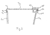
- FIG. 3 is a detail view of the upper portion of the moving container shown in FIG. 2.
- FIG. FIG. 3 shows the first side wall 5a and the first cover element 7a with the first predetermined bending point 9a, a second predetermined bending point 9b and a third predetermined bending point 9c.
- the first lid member 7a is folded toward the second side wall 5c.
- a through hole 13 is arranged, while on the second side wall 5c, a through hole 11 is arranged. Through the holes, a plastic piece 15 is guided, whose ends are so firmly compressed at the point 17 that a closed unit is formed.
- the moving container 41 comprises a box member having a bottom 43 and side walls 45 which extend at an angle to the bottom and of which the first side wall 45a and the second side wall 45c are shown.
- the removal container 41 comprises as lid cover opposing first and second cover elements 47a and 47c, which are arranged at the end remote from the bottom of the first side wall 45a and the second side wall 45c.
- the first cover element 47a or the second cover element 47c is connected to the first side wall 45a or the second side wall 45c via a first predetermined bending point 49a as the first predetermined bending point region or a second predetermined bending point 49c as the second predetermined bending point region.
- the moving container 41 is shown in a closed state, that is, the first lid member 47a and the second lid member 47c are folded by the first predetermined bending point 49a and the second predetermined bending point 49c so as to be angular to the first side wall 45a and the second side wall, respectively 45c is. Further, the second lid member 47c is abutted against the first side wall 45a where the first lid member 47a is disposed, while the first lid member 47a overlies the second lid member 47a Lid member 47c extends and rests on it.
- the first closure means the first cover element 47a has a tab 4113 with a hole 411, while the second side wall 45c has a pin 413 as the second closure means.
- the hole 411 can be arranged around the pin 413 so as to surround it.
- FIG. 5 is a detail view of the closing means of the moving container shown in FIG. 4.
- the second side wall 45c is shown, which is connected to the second cover member 47c via the second predetermined bending point 49c.
- the second lid member 47c is disposed so as to be angularly aligned with the second side wall 45c.
- the pin 413 is arranged as a second closing means in the vicinity of the second predetermined bending point 49c.
- the first cover element 47a which extends over the second cover element 47c, is shown.
- a tab 4113 is formed in one piece with a hole 411 and connected to the first cover element 47a via the third predetermined bending point 449.
- the tab 4413 is folded by means of the predetermined kink 449 almost perpendicular to the first lid member 45a, so that the hole 411 surrounds the pin 413, which is arranged on the second side wall 45c.
- Fig. 6 shows a plan view of an embodiment of a moving container according to the invention.
- the moving container 61 has a box member with short and long sides and a lid.
- the box member comprises a bottom 63 and four side walls 65a, 65b, 65c and 65d.
- the lid includes four lid members 67a, 67b, 67c and 67d.
- the first cover element 67a and the second cover element 67c are located on the long sides of the moving container 61. They are connected to the first side wall by means of a first predetermined buckling point 69a, which forms a first predetermined bending point region, or a second predetermined bending point 69c, which forms a second predetermined bending point region 65a and the second side wall 65c connected.
- the third lid member 67b and the Fourth cover element 67d are located on the short sides of the removal container 61. They are connected to the third side wall 65b or the fourth side wall by means of a third predetermined buckling point 69b, which forms a third predetermined bending point area, or a fourth predetermined buckling point 69d, which forms a fourth predetermined bending point area 65c connected.
- Closure means are disposed on the first lid member 67a and the second side wall 65c.
- the first closure means on the first cover element 67a is an integrally formed with the first cover element tab 613. It is connected via at least one predetermined bending point 6639 with the first cover element 67a.
- the tab 613 has a projection 6613 which protrudes perpendicular to the tab 613.
- the closure means on the second side wall 67c is a through-hole 611 whose shape is adapted to the projection 6613 of the tab 613 such that a positive connection is possible.
- the hole 611 and the projection 6613 can snap into one another such that in a closed removal container 61, a stable, positive click closure is obtained, which can not open by itself, even if a pressure on it by a further moving container stacked on the closed removal container 61 61 is exercised.
- the tab 613 serves to actuate the locking mechanism of the projection 6613 and the through hole 611, so that it can be opened or closed by a light handle. The manner of closure will be explained in detail later with reference to FIG.
- the moving container 61 is shown in the open position.
- the third lid member 67b and the fourth lid member 67d are folded so as to be directed to the inside of the moving container 61 and in a position that is angular, advantageously nearly perpendicular, to the third and fourth Side walls 65b and 65d is.
- the second lid member 67c is folded over the lid members 67b and 67d so as to overlay them and extend to the opposite first side wall 65a.
- the first lid member 67a is folded so as to extend over the second lid member 67c, and such that the protrusion 6613 is inserted into the through hole 11 of the second side wall 65c.
- Fig. 7 shows a cross-sectional view of the closed moving container 61, which is shown in Fig. 61 in plan view in the open position.
- the moving container 61 is provided with the bottom 63, the first side wall 65a, the second side wall 65c, the first lid member 67a, the second lid member 67c, the first predetermined buckling 69a and the second predetermined buckling 69c, and the closing means 611, 613 and 6613 shown, the other elements are not visible.
- the first side wall 65a, the second side wall 65c and the third side wall 65d extend at an angle of 25 ° with respect to the surface normal of the bottom.
- the first and second cover elements 67a and 67c are arranged at the end of the first and second side walls 65a and 65c remote from the bottom 63, respectively.
- the first and second cover element 67a or 67c is connected to the first side wall 65a and the second side wall 65c by means of the first and second predetermined buckling points 69a and 69c, respectively.
- the second lid member 67c is folded relative to the second side wall 65c so as to abut on the first side wall 65a.
- the first lid member 67a extends over the second cover member 67c.
- the angled orientation of the side walls 65a, 65b, 65c and 65d ensures that the bottom 63 has a smaller width and length than the first and second cover elements 67a and 67c, respectively.
- the first cover element 67a has, as closure means, the tab 613 and a projection 6613, while the second side wall 65c has a through-hole 611 as closure means.
- the protrusion 6613 is inserted into the through-hole 611 so that it can not come loose by itself.
- FIG. 8 is an enlarged view of the closure means portion of FIG. 7.
- the second side wall 65c and the second lid member 67c are shown. which are connected via the second predetermined buckling 69c.
- the first lid member 67a extends over the second lid member 67c.
- the tab 613 is arranged, which is foldable by means of the predetermined bending point 6139 with respect to the first cover element 67a.
- the tab 613 has the projection 6613 which is aligned perpendicular to the tab 613.
- the protrusion 6613 is inserted into the through hole 611 formed in the second side wall 67c so that the moving container 61 is closed.
- Fig. 9 is a cross-sectional view showing two stacked transfer containers 91 and 991, respectively, with only visible elements shown.
- the moving container 91 has a bottom 93 and four sidewalls extending angularly therefrom as a box member, of which the three side walls 95a, 95b and 95c are shown, and the fourth side wall is not shown.
- the lid of the moving container comprises a first lid member 97a and a second lid member 97c.
- the moving container 991 has a box member and a lid, the box member including bottom and side walls, while the lid comprises two cover members 997a and 997c.
- the bottom of the moving container 991 is not shown.
- the moving container 991 has three side walls 995a, 995b and 995c shown, the fourth side wall of the moving container 991 is not shown.
- the moving container 91 is in an open state.
- the removal container 91 has a first cover element 97a at the end of the first side wall 95a opposite the bottom 91.
- a second cover element 97 is arranged on the second side wall 95c.
- the first cover element 97a or the second cover element 97c comprises a first predetermined bending point 99a or 99c, by means of which it is angularly, almost vertically, folded with respect to the first side wall 99a and the second side wall 99c.
- the sidewalls 95a, 95b and 95c extend away from the floor 93 at an angle of> 0 ° with respect to the surface normal of the floor.
- the removal container 991 has a first cover element 997a at an end of a first side wall 995a opposite the bottom 993, and a second cover element 997c at a bottom end 993 of a second side wall 995c opposite the first side wall 995a.
- the first cover element 997a or the second cover element 997c is connected to the first side wall 995a and the second side wall 995c via a first predetermined bending point 999a as the first predetermined bending point region or a second predetermined bending point 999c as the second predetermined bending point region.
- the first lid member 995a and the second lid member 995c are formed so as to form one half each of the lid.
- the moving container 991 is in a locked state, so that the first lid member 997a is disposed nearly perpendicular to the first side wall 995a, while the second lid member 997c is disposed nearly perpendicular to the second side wall 995c.
- the end of the second lid member 997c facing the end of the lid member 997c adjacent to the side wall 995c is adjacent to the end of the first lid member 997a opposite to the end of the first lid member 997a adjacent to the first side wall 995a.
- the first lid member 997a and the second lid member 997c have a length and a width larger than the length and the width of the bottom 993.
- first tabs 9913 are respectively one first shutter means each having a further projection (not shown) which is perpendicular to the first projection 9913 and can be inserted into holes (not shown) located in the third side wall 995b.
- the moving containers 91 and 991 can be easily stacked with each other due to the different bottom width with respect to the width of the lid portion, so that they can be stored in a space-saving manner.
- Fig. 10 is an enlarged view of the lid portion of Fig. 9.
- the first side wall 995a is integrally connected to the first lid member 997a, which has the first predetermined buckling point 999a adjacent to the first side wall 995a, by means of which it is folded angularly with respect to the first side wall 995a.
- the second side wall 995c is integrally connected to the second lid member 995c via the second predetermined buckling point 999c.
- the four lugs 9913 integrally formed on the first cover element 997a and the second cover element 997c are folded parallel to the third side wall 995b by means of the predetermined bending point 9999 lying between the respective projection 9913 and the first cover element 997a and the second cover element 997c Side wall 995a and the second side wall 995c is arranged.
- Each tab 9913 has a further projection (not shown) formed perpendicular to it and one of each of the holes (not shown) formed in the third side wall 995b is inserted.
- the first cover element 997a and the third cover element 997c each have a first edge region 994a or a second edge region 994c, which is raised relative to the first region 996a or the second region 996c.
Landscapes
- Engineering & Computer Science (AREA)
- Mechanical Engineering (AREA)
- Stackable Containers (AREA)
Priority Applications (1)
| Application Number | Priority Date | Filing Date | Title |
|---|---|---|---|
| EP05090348A EP1801027A1 (fr) | 2005-12-23 | 2005-12-23 | Récipient de déménagement d'une seule pièce |
Applications Claiming Priority (1)
| Application Number | Priority Date | Filing Date | Title |
|---|---|---|---|
| EP05090348A EP1801027A1 (fr) | 2005-12-23 | 2005-12-23 | Récipient de déménagement d'une seule pièce |
Publications (1)
| Publication Number | Publication Date |
|---|---|
| EP1801027A1 true EP1801027A1 (fr) | 2007-06-27 |
Family
ID=36570703
Family Applications (1)
| Application Number | Title | Priority Date | Filing Date |
|---|---|---|---|
| EP05090348A Withdrawn EP1801027A1 (fr) | 2005-12-23 | 2005-12-23 | Récipient de déménagement d'une seule pièce |
Country Status (1)
| Country | Link |
|---|---|
| EP (1) | EP1801027A1 (fr) |
Citations (7)
| Publication number | Priority date | Publication date | Assignee | Title |
|---|---|---|---|---|
| US2885135A (en) * | 1954-09-07 | 1959-05-05 | Paper Maid Inc | Molded pulp container |
| US3629901A (en) * | 1968-04-30 | 1971-12-28 | Maria Hermine Wolf | Hinges |
| US3900550A (en) * | 1970-04-24 | 1975-08-19 | Dow Chemical Co | Method of enhancing flexure of plastic hinges |
| US5016777A (en) * | 1990-01-11 | 1991-05-21 | Morley Marvin | Expandable polystyrene container hinge and method of forming |
| US5204130A (en) * | 1991-07-11 | 1993-04-20 | Kraft General Foods, Inc. | Reclosable container for sliced food products |
| FR2706424A1 (fr) * | 1993-06-15 | 1994-12-23 | Allibert Manutention Sa | Bac équipé d'un couvercle à verrouillage perfectionné. |
| US20050218150A1 (en) * | 1996-01-24 | 2005-10-06 | Sambrailo Packaging, Inc. | Produce packaging container with dual hinged resealable tops |
-
2005
- 2005-12-23 EP EP05090348A patent/EP1801027A1/fr not_active Withdrawn
Patent Citations (7)
| Publication number | Priority date | Publication date | Assignee | Title |
|---|---|---|---|---|
| US2885135A (en) * | 1954-09-07 | 1959-05-05 | Paper Maid Inc | Molded pulp container |
| US3629901A (en) * | 1968-04-30 | 1971-12-28 | Maria Hermine Wolf | Hinges |
| US3900550A (en) * | 1970-04-24 | 1975-08-19 | Dow Chemical Co | Method of enhancing flexure of plastic hinges |
| US5016777A (en) * | 1990-01-11 | 1991-05-21 | Morley Marvin | Expandable polystyrene container hinge and method of forming |
| US5204130A (en) * | 1991-07-11 | 1993-04-20 | Kraft General Foods, Inc. | Reclosable container for sliced food products |
| FR2706424A1 (fr) * | 1993-06-15 | 1994-12-23 | Allibert Manutention Sa | Bac équipé d'un couvercle à verrouillage perfectionné. |
| US20050218150A1 (en) * | 1996-01-24 | 2005-10-06 | Sambrailo Packaging, Inc. | Produce packaging container with dual hinged resealable tops |
Similar Documents
| Publication | Publication Date | Title |
|---|---|---|
| DE69509505T2 (de) | Behälter oder behälterdeckel aus steifem flachmaterial sowie zuschnitt und verfahren zu dessen herstellung | |
| DE60219214T2 (de) | Kindersichere verpackung mit verschiebbarem einsatzabschnitt | |
| DE69501267T2 (de) | Zuschnitt zur Herstellung einer leicht zu öffnenden amerikanischen Schachtel, sowie so hergestellte Schachtel | |
| DE69404853T2 (de) | Schachtel oder schachteldeckel aus steifem flachmaterial mit handgriff, sowie zuschnitt und verfahren zur herstellung derselben | |
| DE3883396T2 (de) | Abschliessbare dose. | |
| EP1783058B1 (fr) | Emballage à l'épreuve des enfants | |
| DE69315956T2 (de) | Faltschachtel | |
| EP3981700A1 (fr) | Récipient pouvant être refermé, en particulier récipient à sécurité pour enfants pouvant être refermé | |
| DE9111080U1 (de) | Verpackungsdose | |
| EP3854714B1 (fr) | Boîte pliante | |
| DE69728305T2 (de) | Zuschnitte für Schachtel in der Form einer Schauverpackung und aus ihnen hergestellte Schachtel | |
| DE3037109A1 (de) | Packung mit klappdeckelverschluss | |
| EP4098573B1 (fr) | Emballage pliant | |
| DE69601027T2 (de) | Verpackungsschachtel mit sicherheitsverschluss | |
| EP2028114A1 (fr) | Boîte pliable | |
| EP1801027A1 (fr) | Récipient de déménagement d'une seule pièce | |
| DE69707199T2 (de) | Dokumentenhalter | |
| AT413813B (de) | Behälter mit deckel, mit drehverschluss, aus flachem material | |
| AT4610U1 (de) | Zigaretten-packung | |
| DE9203448U1 (de) | Zweischalenbehälter | |
| DE8017829U1 (de) | Behaelter fuer den Transport gefaehrlicher Fluessigkeiten | |
| DE29820547U1 (de) | Vielseitig verwendbare Faltschachtel | |
| DE202024101263U1 (de) | Behälter, und Zuschnitt zur Herstellung eines Behälters | |
| DE102023102090A1 (de) | Faltschachtel | |
| DE102023002689A1 (de) | Verpackungseinheit mit arretierbarem, innerem Trägerelement für Produkte |
Legal Events
| Date | Code | Title | Description |
|---|---|---|---|
| PUAI | Public reference made under article 153(3) epc to a published international application that has entered the european phase |
Free format text: ORIGINAL CODE: 0009012 |
|
| AK | Designated contracting states |
Kind code of ref document: A1 Designated state(s): AT BE BG CH CY CZ DE DK EE ES FI FR GB GR HU IE IS IT LI LT LU LV MC NL PL PT RO SE SI SK TR |
|
| AX | Request for extension of the european patent |
Extension state: AL BA HR MK YU |
|
| AKX | Designation fees paid | ||
| STAA | Information on the status of an ep patent application or granted ep patent |
Free format text: STATUS: THE APPLICATION IS DEEMED TO BE WITHDRAWN |
|
| 18D | Application deemed to be withdrawn |
Effective date: 20071228 |
|
| REG | Reference to a national code |
Ref country code: DE Ref legal event code: 8566 |