EP1801083A1 - Partikelförmige, korrosionsfeste Beschichtungszusammensetzung, beschichtete Turbinenkomponente und Beschichtungsverfahren dafür - Google Patents
Partikelförmige, korrosionsfeste Beschichtungszusammensetzung, beschichtete Turbinenkomponente und Beschichtungsverfahren dafür Download PDFInfo
- Publication number
- EP1801083A1 EP1801083A1 EP06126604A EP06126604A EP1801083A1 EP 1801083 A1 EP1801083 A1 EP 1801083A1 EP 06126604 A EP06126604 A EP 06126604A EP 06126604 A EP06126604 A EP 06126604A EP 1801083 A1 EP1801083 A1 EP 1801083A1
- Authority
- EP
- European Patent Office
- Prior art keywords
- cte
- corrosion resistant
- less
- particulates
- turbine
- Prior art date
- Legal status (The legal status is an assumption and is not a legal conclusion. Google has not performed a legal analysis and makes no representation as to the accuracy of the status listed.)
- Ceased
Links
- 230000007797 corrosion Effects 0.000 title claims abstract description 180
- 238000005260 corrosion Methods 0.000 title claims abstract description 180
- 238000000576 coating method Methods 0.000 title claims abstract description 129
- 239000011248 coating agent Substances 0.000 title claims abstract description 96
- 238000000034 method Methods 0.000 title abstract description 16
- 239000008199 coating composition Substances 0.000 title description 43
- GOHCTCOGYKAJLZ-UHFFFAOYSA-N ctep Chemical compound CC=1N(C=2C=CC(OC(F)(F)F)=CC=2)C(C)=NC=1C#CC1=CC=NC(Cl)=C1 GOHCTCOGYKAJLZ-UHFFFAOYSA-N 0.000 claims abstract description 87
- 229910052751 metal Inorganic materials 0.000 claims abstract description 69
- 239000002184 metal Substances 0.000 claims abstract description 69
- 239000002245 particle Substances 0.000 claims abstract description 67
- 239000000758 substrate Substances 0.000 claims abstract description 57
- 239000000203 mixture Substances 0.000 claims abstract description 48
- 239000011230 binding agent Substances 0.000 claims abstract description 44
- 238000007496 glass forming Methods 0.000 claims abstract description 17
- 239000007787 solid Substances 0.000 claims abstract description 15
- PXHVJJICTQNCMI-UHFFFAOYSA-N Nickel Chemical group [Ni] PXHVJJICTQNCMI-UHFFFAOYSA-N 0.000 claims description 31
- 239000007788 liquid Substances 0.000 claims description 16
- PNEYBMLMFCGWSK-UHFFFAOYSA-N aluminium oxide Inorganic materials [O-2].[O-2].[O-2].[Al+3].[Al+3] PNEYBMLMFCGWSK-UHFFFAOYSA-N 0.000 claims description 15
- 229910052759 nickel Inorganic materials 0.000 claims description 15
- 229910019142 PO4 Inorganic materials 0.000 claims description 14
- 239000010452 phosphate Substances 0.000 claims description 14
- NBIIXXVUZAFLBC-UHFFFAOYSA-K phosphate Chemical compound [O-]P([O-])([O-])=O NBIIXXVUZAFLBC-UHFFFAOYSA-K 0.000 claims description 12
- 229910045601 alloy Chemical group 0.000 claims description 11
- 239000000956 alloy Chemical group 0.000 claims description 11
- 229910001092 metal group alloy Inorganic materials 0.000 claims description 10
- XEEYBQQBJWHFJM-UHFFFAOYSA-N Iron Chemical group [Fe] XEEYBQQBJWHFJM-UHFFFAOYSA-N 0.000 claims description 8
- 239000010941 cobalt Chemical group 0.000 claims description 8
- GUTLYIVDDKVIGB-UHFFFAOYSA-N cobalt atom Chemical group [Co] GUTLYIVDDKVIGB-UHFFFAOYSA-N 0.000 claims description 8
- 229910017052 cobalt Inorganic materials 0.000 claims description 7
- 241000588731 Hafnia Species 0.000 claims description 6
- KDLHZDBZIXYQEI-UHFFFAOYSA-N Palladium Chemical group [Pd] KDLHZDBZIXYQEI-UHFFFAOYSA-N 0.000 claims description 6
- BASFCYQUMIYNBI-UHFFFAOYSA-N platinum Chemical group [Pt] BASFCYQUMIYNBI-UHFFFAOYSA-N 0.000 claims description 6
- CJNBYAVZURUTKZ-UHFFFAOYSA-N hafnium(IV) oxide Inorganic materials O=[Hf]=O CJNBYAVZURUTKZ-UHFFFAOYSA-N 0.000 claims description 5
- CPLXHLVBOLITMK-UHFFFAOYSA-N Magnesium oxide Chemical compound [Mg]=O CPLXHLVBOLITMK-UHFFFAOYSA-N 0.000 claims description 4
- XUIMIQQOPSSXEZ-UHFFFAOYSA-N Silicon Chemical group [Si] XUIMIQQOPSSXEZ-UHFFFAOYSA-N 0.000 claims description 4
- QCWXUUIWCKQGHC-UHFFFAOYSA-N Zirconium Chemical group [Zr] QCWXUUIWCKQGHC-UHFFFAOYSA-N 0.000 claims description 4
- QDOXWKRWXJOMAK-UHFFFAOYSA-N dichromium trioxide Chemical compound O=[Cr]O[Cr]=O QDOXWKRWXJOMAK-UHFFFAOYSA-N 0.000 claims description 4
- 229910052742 iron Inorganic materials 0.000 claims description 4
- 229910052746 lanthanum Inorganic materials 0.000 claims description 4
- FZLIPJUXYLNCLC-UHFFFAOYSA-N lanthanum atom Chemical group [La] FZLIPJUXYLNCLC-UHFFFAOYSA-N 0.000 claims description 4
- 239000010703 silicon Chemical group 0.000 claims description 4
- GUVRBAGPIYLISA-UHFFFAOYSA-N tantalum atom Chemical group [Ta] GUVRBAGPIYLISA-UHFFFAOYSA-N 0.000 claims description 4
- 229910052727 yttrium Inorganic materials 0.000 claims description 4
- VWQVUPCCIRVNHF-UHFFFAOYSA-N yttrium atom Chemical group [Y] VWQVUPCCIRVNHF-UHFFFAOYSA-N 0.000 claims description 4
- 229910052726 zirconium Inorganic materials 0.000 claims description 4
- 229910052735 hafnium Inorganic materials 0.000 claims description 3
- VBJZVLUMGGDVMO-UHFFFAOYSA-N hafnium atom Chemical group [Hf] VBJZVLUMGGDVMO-UHFFFAOYSA-N 0.000 claims description 3
- 229910052763 palladium Inorganic materials 0.000 claims description 3
- 229910052697 platinum Inorganic materials 0.000 claims description 3
- 229910052710 silicon Inorganic materials 0.000 claims description 3
- 229910052715 tantalum Inorganic materials 0.000 claims description 3
- 239000000395 magnesium oxide Substances 0.000 claims description 2
- 229910052702 rhenium Inorganic materials 0.000 claims description 2
- WUAPFZMCVAUBPE-UHFFFAOYSA-N rhenium atom Chemical group [Re] WUAPFZMCVAUBPE-UHFFFAOYSA-N 0.000 claims description 2
- 229910001233 yttria-stabilized zirconia Inorganic materials 0.000 claims description 2
- 239000010410 layer Substances 0.000 description 80
- 229910052782 aluminium Inorganic materials 0.000 description 18
- 229910052804 chromium Inorganic materials 0.000 description 17
- 239000011651 chromium Substances 0.000 description 17
- 238000009826 distribution Methods 0.000 description 17
- 239000007789 gas Substances 0.000 description 13
- 239000000463 material Substances 0.000 description 13
- 235000021317 phosphate Nutrition 0.000 description 13
- XAGFODPZIPBFFR-UHFFFAOYSA-N aluminium Chemical compound [Al] XAGFODPZIPBFFR-UHFFFAOYSA-N 0.000 description 12
- 150000002739 metals Chemical class 0.000 description 12
- -1 platinum group metals Chemical class 0.000 description 12
- 229910000601 superalloy Inorganic materials 0.000 description 12
- 239000000919 ceramic Substances 0.000 description 11
- 230000002902 bimodal effect Effects 0.000 description 7
- 238000000151 deposition Methods 0.000 description 7
- 239000000565 sealant Substances 0.000 description 7
- VYZAMTAEIAYCRO-UHFFFAOYSA-N Chromium Chemical compound [Cr] VYZAMTAEIAYCRO-UHFFFAOYSA-N 0.000 description 6
- MCMNRKCIXSYSNV-UHFFFAOYSA-N Zirconium dioxide Chemical compound O=[Zr]=O MCMNRKCIXSYSNV-UHFFFAOYSA-N 0.000 description 6
- 229910002076 stabilized zirconia Inorganic materials 0.000 description 6
- VYPSYNLAJGMNEJ-UHFFFAOYSA-N Silicium dioxide Chemical class O=[Si]=O VYPSYNLAJGMNEJ-UHFFFAOYSA-N 0.000 description 5
- ZCDOYSPFYFSLEW-UHFFFAOYSA-N chromate(2-) Chemical compound [O-][Cr]([O-])(=O)=O ZCDOYSPFYFSLEW-UHFFFAOYSA-N 0.000 description 5
- 238000009792 diffusion process Methods 0.000 description 5
- 239000011159 matrix material Substances 0.000 description 5
- RUDFQVOCFDJEEF-UHFFFAOYSA-N oxygen(2-);yttrium(3+) Chemical class [O-2].[O-2].[O-2].[Y+3].[Y+3] RUDFQVOCFDJEEF-UHFFFAOYSA-N 0.000 description 5
- 239000004094 surface-active agent Substances 0.000 description 5
- 230000008901 benefit Effects 0.000 description 4
- 238000005422 blasting Methods 0.000 description 4
- 150000004649 carbonic acid derivatives Chemical class 0.000 description 4
- 238000005229 chemical vapour deposition Methods 0.000 description 4
- 150000001805 chlorine compounds Chemical class 0.000 description 4
- 230000008569 process Effects 0.000 description 4
- 150000003839 salts Chemical class 0.000 description 4
- 235000002639 sodium chloride Nutrition 0.000 description 4
- LSNNMFCWUKXFEE-UHFFFAOYSA-L sulfite Chemical class [O-]S([O-])=O LSNNMFCWUKXFEE-UHFFFAOYSA-L 0.000 description 4
- XLYOFNOQVPJJNP-UHFFFAOYSA-N water Substances O XLYOFNOQVPJJNP-UHFFFAOYSA-N 0.000 description 4
- 229910000531 Co alloy Inorganic materials 0.000 description 3
- LYCAIKOWRPUZTN-UHFFFAOYSA-N Ethylene glycol Chemical compound OCCO LYCAIKOWRPUZTN-UHFFFAOYSA-N 0.000 description 3
- RTAQQCXQSZGOHL-UHFFFAOYSA-N Titanium Chemical compound [Ti] RTAQQCXQSZGOHL-UHFFFAOYSA-N 0.000 description 3
- ILRRQNADMUWWFW-UHFFFAOYSA-K aluminium phosphate Chemical class O1[Al]2OP1(=O)O2 ILRRQNADMUWWFW-UHFFFAOYSA-K 0.000 description 3
- 239000002956 ash Substances 0.000 description 3
- JOPOVCBBYLSVDA-UHFFFAOYSA-N chromium(6+) Chemical compound [Cr+6] JOPOVCBBYLSVDA-UHFFFAOYSA-N 0.000 description 3
- 230000001419 dependent effect Effects 0.000 description 3
- 239000000428 dust Substances 0.000 description 3
- 230000009969 flowable effect Effects 0.000 description 3
- 239000010881 fly ash Substances 0.000 description 3
- 238000010438 heat treatment Methods 0.000 description 3
- GVALZJMUIHGIMD-UHFFFAOYSA-H magnesium phosphate Chemical class [Mg+2].[Mg+2].[Mg+2].[O-]P([O-])([O-])=O.[O-]P([O-])([O-])=O GVALZJMUIHGIMD-UHFFFAOYSA-H 0.000 description 3
- 239000004137 magnesium phosphate Substances 0.000 description 3
- 235000010994 magnesium phosphates Nutrition 0.000 description 3
- 238000002844 melting Methods 0.000 description 3
- 230000008018 melting Effects 0.000 description 3
- 150000004767 nitrides Chemical class 0.000 description 3
- 230000003647 oxidation Effects 0.000 description 3
- 238000007254 oxidation reaction Methods 0.000 description 3
- 239000002694 phosphate binding agent Substances 0.000 description 3
- 230000003068 static effect Effects 0.000 description 3
- 239000000126 substance Substances 0.000 description 3
- 150000003467 sulfuric acid derivatives Chemical class 0.000 description 3
- 239000010936 titanium Substances 0.000 description 3
- CSCPPACGZOOCGX-UHFFFAOYSA-N Acetone Chemical compound CC(C)=O CSCPPACGZOOCGX-UHFFFAOYSA-N 0.000 description 2
- LFQSCWFLJHTTHZ-UHFFFAOYSA-N Ethanol Chemical compound CCO LFQSCWFLJHTTHZ-UHFFFAOYSA-N 0.000 description 2
- KRHYYFGTRYWZRS-UHFFFAOYSA-N Fluorane Chemical compound F KRHYYFGTRYWZRS-UHFFFAOYSA-N 0.000 description 2
- VEXZGXHMUGYJMC-UHFFFAOYSA-N Hydrochloric acid Chemical compound Cl VEXZGXHMUGYJMC-UHFFFAOYSA-N 0.000 description 2
- KFZMGEQAYNKOFK-UHFFFAOYSA-N Isopropanol Chemical compound CC(C)O KFZMGEQAYNKOFK-UHFFFAOYSA-N 0.000 description 2
- NBIIXXVUZAFLBC-UHFFFAOYSA-N Phosphoric acid Chemical compound OP(O)(O)=O NBIIXXVUZAFLBC-UHFFFAOYSA-N 0.000 description 2
- QAOWNCQODCNURD-UHFFFAOYSA-L Sulfate Chemical compound [O-]S([O-])(=O)=O QAOWNCQODCNURD-UHFFFAOYSA-L 0.000 description 2
- GWEVSGVZZGPLCZ-UHFFFAOYSA-N Titan oxide Chemical compound O=[Ti]=O GWEVSGVZZGPLCZ-UHFFFAOYSA-N 0.000 description 2
- QXZUUHYBWMWJHK-UHFFFAOYSA-N [Co].[Ni] Chemical group [Co].[Ni] QXZUUHYBWMWJHK-UHFFFAOYSA-N 0.000 description 2
- 230000002411 adverse Effects 0.000 description 2
- 239000008365 aqueous carrier Substances 0.000 description 2
- GVEHJMMRQRRJPM-UHFFFAOYSA-N chromium(2+);methanidylidynechromium Chemical compound [Cr+2].[Cr]#[C-].[Cr]#[C-] GVEHJMMRQRRJPM-UHFFFAOYSA-N 0.000 description 2
- IKZBVTPSNGOVRJ-UHFFFAOYSA-K chromium(iii) phosphate Chemical class [Cr+3].[O-]P([O-])([O-])=O IKZBVTPSNGOVRJ-UHFFFAOYSA-K 0.000 description 2
- 239000000567 combustion gas Substances 0.000 description 2
- 230000007423 decrease Effects 0.000 description 2
- 238000005516 engineering process Methods 0.000 description 2
- 230000001788 irregular Effects 0.000 description 2
- 229910000157 magnesium phosphate Inorganic materials 0.000 description 2
- 229960002261 magnesium phosphate Drugs 0.000 description 2
- 239000003960 organic solvent Substances 0.000 description 2
- 238000012856 packing Methods 0.000 description 2
- 238000005240 physical vapour deposition Methods 0.000 description 2
- 239000000049 pigment Substances 0.000 description 2
- 239000000843 powder Substances 0.000 description 2
- 239000002356 single layer Substances 0.000 description 2
- 238000004901 spalling Methods 0.000 description 2
- 238000005507 spraying Methods 0.000 description 2
- 230000009974 thixotropic effect Effects 0.000 description 2
- 229910052719 titanium Inorganic materials 0.000 description 2
- 229910003470 tongbaite Inorganic materials 0.000 description 2
- 239000011800 void material Substances 0.000 description 2
- LXOFYPKXCSULTL-UHFFFAOYSA-N 2,4,7,9-tetramethyldec-5-yne-4,7-diol Chemical compound CC(C)CC(C)(O)C#CC(C)(O)CC(C)C LXOFYPKXCSULTL-UHFFFAOYSA-N 0.000 description 1
- 229910000838 Al alloy Inorganic materials 0.000 description 1
- 229910000951 Aluminide Inorganic materials 0.000 description 1
- QGZKDVFQNNGYKY-UHFFFAOYSA-O Ammonium Chemical compound [NH4+] QGZKDVFQNNGYKY-UHFFFAOYSA-O 0.000 description 1
- 239000004135 Bone phosphate Substances 0.000 description 1
- ZOXJGFHDIHLPTG-UHFFFAOYSA-N Boron Chemical compound [B] ZOXJGFHDIHLPTG-UHFFFAOYSA-N 0.000 description 1
- OKTJSMMVPCPJKN-UHFFFAOYSA-N Carbon Chemical compound [C] OKTJSMMVPCPJKN-UHFFFAOYSA-N 0.000 description 1
- 229910000640 Fe alloy Inorganic materials 0.000 description 1
- FYYHWMGAXLPEAU-UHFFFAOYSA-N Magnesium Chemical compound [Mg] FYYHWMGAXLPEAU-UHFFFAOYSA-N 0.000 description 1
- ZOKXTWBITQBERF-UHFFFAOYSA-N Molybdenum Chemical compound [Mo] ZOKXTWBITQBERF-UHFFFAOYSA-N 0.000 description 1
- 229910000990 Ni alloy Inorganic materials 0.000 description 1
- GRYLNZFGIOXLOG-UHFFFAOYSA-N Nitric acid Chemical compound O[N+]([O-])=O GRYLNZFGIOXLOG-UHFFFAOYSA-N 0.000 description 1
- NPXOKRUENSOPAO-UHFFFAOYSA-N Raney nickel Chemical compound [Al].[Ni] NPXOKRUENSOPAO-UHFFFAOYSA-N 0.000 description 1
- 229910000831 Steel Inorganic materials 0.000 description 1
- WGLPBDUCMAPZCE-UHFFFAOYSA-N Trioxochromium Chemical compound O=[Cr](=O)=O WGLPBDUCMAPZCE-UHFFFAOYSA-N 0.000 description 1
- 230000002378 acidificating effect Effects 0.000 description 1
- 230000009471 action Effects 0.000 description 1
- 150000001298 alcohols Chemical class 0.000 description 1
- 150000004645 aluminates Chemical class 0.000 description 1
- 229910000147 aluminium phosphate Inorganic materials 0.000 description 1
- 150000001412 amines Chemical group 0.000 description 1
- 239000002280 amphoteric surfactant Substances 0.000 description 1
- 239000003945 anionic surfactant Substances 0.000 description 1
- QVGXLLKOCUKJST-UHFFFAOYSA-N atomic oxygen Chemical compound [O] QVGXLLKOCUKJST-UHFFFAOYSA-N 0.000 description 1
- 230000015572 biosynthetic process Effects 0.000 description 1
- BUOSLGZEBFSUDD-BGPZCGNYSA-N bis[(1s,3s,4r,5r)-4-methoxycarbonyl-8-methyl-8-azabicyclo[3.2.1]octan-3-yl] 2,4-diphenylcyclobutane-1,3-dicarboxylate Chemical compound O([C@H]1C[C@@H]2CC[C@@H](N2C)[C@H]1C(=O)OC)C(=O)C1C(C=2C=CC=CC=2)C(C(=O)O[C@@H]2[C@@H]([C@H]3CC[C@H](N3C)C2)C(=O)OC)C1C1=CC=CC=C1 BUOSLGZEBFSUDD-BGPZCGNYSA-N 0.000 description 1
- 229910052796 boron Inorganic materials 0.000 description 1
- 239000000872 buffer Substances 0.000 description 1
- 229910002084 calcia-stabilized zirconia Inorganic materials 0.000 description 1
- 239000001506 calcium phosphate Substances 0.000 description 1
- 235000011010 calcium phosphates Nutrition 0.000 description 1
- 229910052799 carbon Inorganic materials 0.000 description 1
- 125000002091 cationic group Chemical group 0.000 description 1
- 239000003093 cationic surfactant Substances 0.000 description 1
- 229910002086 ceria-stabilized zirconia Inorganic materials 0.000 description 1
- CETPSERCERDGAM-UHFFFAOYSA-N ceric oxide Chemical compound O=[Ce]=O CETPSERCERDGAM-UHFFFAOYSA-N 0.000 description 1
- 229910000422 cerium(IV) oxide Inorganic materials 0.000 description 1
- 239000003795 chemical substances by application Substances 0.000 description 1
- 229910000423 chromium oxide Inorganic materials 0.000 description 1
- 229910000151 chromium(III) phosphate Inorganic materials 0.000 description 1
- 239000011247 coating layer Substances 0.000 description 1
- 229940117583 cocamine Drugs 0.000 description 1
- 230000001427 coherent effect Effects 0.000 description 1
- 239000003086 colorant Substances 0.000 description 1
- 238000002485 combustion reaction Methods 0.000 description 1
- 239000000306 component Substances 0.000 description 1
- 150000001875 compounds Chemical class 0.000 description 1
- 238000001816 cooling Methods 0.000 description 1
- 125000004122 cyclic group Chemical group 0.000 description 1
- 230000003247 decreasing effect Effects 0.000 description 1
- 230000032798 delamination Effects 0.000 description 1
- 235000011180 diphosphates Nutrition 0.000 description 1
- 238000007598 dipping method Methods 0.000 description 1
- 229910001651 emery Inorganic materials 0.000 description 1
- 239000000446 fuel Substances 0.000 description 1
- 229940083124 ganglion-blocking antiadrenergic secondary and tertiary amines Drugs 0.000 description 1
- 239000002223 garnet Substances 0.000 description 1
- 150000002334 glycols Chemical group 0.000 description 1
- 238000000227 grinding Methods 0.000 description 1
- 229910000856 hastalloy Inorganic materials 0.000 description 1
- 239000012535 impurity Substances 0.000 description 1
- 229910001026 inconel Inorganic materials 0.000 description 1
- 150000002484 inorganic compounds Chemical class 0.000 description 1
- 229910010272 inorganic material Inorganic materials 0.000 description 1
- 229910052741 iridium Inorganic materials 0.000 description 1
- GKOZUEZYRPOHIO-UHFFFAOYSA-N iridium atom Chemical compound [Ir] GKOZUEZYRPOHIO-UHFFFAOYSA-N 0.000 description 1
- WBJZTOZJJYAKHQ-UHFFFAOYSA-K iron(3+) phosphate Chemical class [Fe+3].[O-]P([O-])([O-])=O WBJZTOZJJYAKHQ-UHFFFAOYSA-K 0.000 description 1
- 238000010329 laser etching Methods 0.000 description 1
- 238000011068 loading method Methods 0.000 description 1
- 229910002085 magnesia-stabilized zirconia Inorganic materials 0.000 description 1
- 229910052749 magnesium Inorganic materials 0.000 description 1
- 239000011777 magnesium Substances 0.000 description 1
- 238000004519 manufacturing process Methods 0.000 description 1
- 230000000873 masking effect Effects 0.000 description 1
- 230000013011 mating Effects 0.000 description 1
- 150000001247 metal acetylides Chemical class 0.000 description 1
- 229910044991 metal oxide Inorganic materials 0.000 description 1
- 150000004706 metal oxides Chemical class 0.000 description 1
- 229910001463 metal phosphate Inorganic materials 0.000 description 1
- 238000005459 micromachining Methods 0.000 description 1
- 238000012986 modification Methods 0.000 description 1
- 230000004048 modification Effects 0.000 description 1
- 229910052750 molybdenum Inorganic materials 0.000 description 1
- 239000011733 molybdenum Substances 0.000 description 1
- 229910001235 nimonic Inorganic materials 0.000 description 1
- 229910052758 niobium Inorganic materials 0.000 description 1
- 239000010955 niobium Substances 0.000 description 1
- GUCVJGMIXFAOAE-UHFFFAOYSA-N niobium atom Chemical compound [Nb] GUCVJGMIXFAOAE-UHFFFAOYSA-N 0.000 description 1
- 229910017604 nitric acid Inorganic materials 0.000 description 1
- 239000002736 nonionic surfactant Substances 0.000 description 1
- 239000011368 organic material Substances 0.000 description 1
- 229910052760 oxygen Inorganic materials 0.000 description 1
- 239000001301 oxygen Substances 0.000 description 1
- 238000001556 precipitation Methods 0.000 description 1
- 230000002028 premature Effects 0.000 description 1
- 238000002203 pretreatment Methods 0.000 description 1
- 230000001737 promoting effect Effects 0.000 description 1
- BDERNNFJNOPAEC-UHFFFAOYSA-N propan-1-ol Chemical compound CCCO BDERNNFJNOPAEC-UHFFFAOYSA-N 0.000 description 1
- 239000011253 protective coating Substances 0.000 description 1
- 238000010298 pulverizing process Methods 0.000 description 1
- 230000002829 reductive effect Effects 0.000 description 1
- 230000008439 repair process Effects 0.000 description 1
- 229910052703 rhodium Inorganic materials 0.000 description 1
- 239000010948 rhodium Substances 0.000 description 1
- MHOVAHRLVXNVSD-UHFFFAOYSA-N rhodium atom Chemical compound [Rh] MHOVAHRLVXNVSD-UHFFFAOYSA-N 0.000 description 1
- 238000005096 rolling process Methods 0.000 description 1
- HBMJWWWQQXIZIP-UHFFFAOYSA-N silicon carbide Chemical compound [Si+]#[C-] HBMJWWWQQXIZIP-UHFFFAOYSA-N 0.000 description 1
- 229910010271 silicon carbide Inorganic materials 0.000 description 1
- 239000000377 silicon dioxide Substances 0.000 description 1
- 229910052814 silicon oxide Inorganic materials 0.000 description 1
- 229960000776 sodium tetradecyl sulfate Drugs 0.000 description 1
- DGSDBJMBHCQYGN-UHFFFAOYSA-M sodium;2-ethylhexyl sulfate Chemical compound [Na+].CCCCC(CC)COS([O-])(=O)=O DGSDBJMBHCQYGN-UHFFFAOYSA-M 0.000 description 1
- HHURSJAUVYNJBT-UHFFFAOYSA-M sodium;heptadecyl sulfate Chemical compound [Na+].CCCCCCCCCCCCCCCCCOS([O-])(=O)=O HHURSJAUVYNJBT-UHFFFAOYSA-M 0.000 description 1
- UPUIQOIQVMNQAP-UHFFFAOYSA-M sodium;tetradecyl sulfate Chemical compound [Na+].CCCCCCCCCCCCCCOS([O-])(=O)=O UPUIQOIQVMNQAP-UHFFFAOYSA-M 0.000 description 1
- 239000007921 spray Substances 0.000 description 1
- 239000010959 steel Substances 0.000 description 1
- 230000002459 sustained effect Effects 0.000 description 1
- 229910001936 tantalum oxide Inorganic materials 0.000 description 1
- OGIDPMRJRNCKJF-UHFFFAOYSA-N titanium oxide Inorganic materials [Ti]=O OGIDPMRJRNCKJF-UHFFFAOYSA-N 0.000 description 1
- QORWJWZARLRLPR-UHFFFAOYSA-H tricalcium bis(phosphate) Chemical class [Ca+2].[Ca+2].[Ca+2].[O-]P([O-])([O-])=O.[O-]P([O-])([O-])=O QORWJWZARLRLPR-UHFFFAOYSA-H 0.000 description 1
- TWQULNDIKKJZPH-UHFFFAOYSA-K trilithium;phosphate Chemical class [Li+].[Li+].[Li+].[O-]P([O-])([O-])=O TWQULNDIKKJZPH-UHFFFAOYSA-K 0.000 description 1
- GPRLSGONYQIRFK-MNYXATJNSA-N triton Chemical compound [3H+] GPRLSGONYQIRFK-MNYXATJNSA-N 0.000 description 1
- WFKWXMTUELFFGS-UHFFFAOYSA-N tungsten Chemical compound [W] WFKWXMTUELFFGS-UHFFFAOYSA-N 0.000 description 1
- 229910052721 tungsten Inorganic materials 0.000 description 1
- 239000010937 tungsten Substances 0.000 description 1
- LRXTYHSAJDENHV-UHFFFAOYSA-H zinc phosphate Chemical class [Zn+2].[Zn+2].[Zn+2].[O-]P([O-])([O-])=O.[O-]P([O-])([O-])=O LRXTYHSAJDENHV-UHFFFAOYSA-H 0.000 description 1
- 239000002888 zwitterionic surfactant Substances 0.000 description 1
Images


Classifications
-
- C—CHEMISTRY; METALLURGY
- C23—COATING METALLIC MATERIAL; COATING MATERIAL WITH METALLIC MATERIAL; CHEMICAL SURFACE TREATMENT; DIFFUSION TREATMENT OF METALLIC MATERIAL; COATING BY VACUUM EVAPORATION, BY SPUTTERING, BY ION IMPLANTATION OR BY CHEMICAL VAPOUR DEPOSITION, IN GENERAL; INHIBITING CORROSION OF METALLIC MATERIAL OR INCRUSTATION IN GENERAL
- C23C—COATING METALLIC MATERIAL; COATING MATERIAL WITH METALLIC MATERIAL; SURFACE TREATMENT OF METALLIC MATERIAL BY DIFFUSION INTO THE SURFACE, BY CHEMICAL CONVERSION OR SUBSTITUTION; COATING BY VACUUM EVAPORATION, BY SPUTTERING, BY ION IMPLANTATION OR BY CHEMICAL VAPOUR DEPOSITION, IN GENERAL
- C23C24/00—Coating starting from inorganic powder
- C23C24/08—Coating starting from inorganic powder by application of heat or pressure and heat
-
- C—CHEMISTRY; METALLURGY
- C03—GLASS; MINERAL OR SLAG WOOL
- C03C—CHEMICAL COMPOSITION OF GLASSES, GLAZES OR VITREOUS ENAMELS; SURFACE TREATMENT OF GLASS; SURFACE TREATMENT OF FIBRES OR FILAMENTS MADE FROM GLASS, MINERALS OR SLAGS; JOINING GLASS TO GLASS OR OTHER MATERIALS
- C03C1/00—Ingredients generally applicable to manufacture of glasses, glazes, or vitreous enamels
- C03C1/006—Ingredients generally applicable to manufacture of glasses, glazes, or vitreous enamels to produce glass through wet route
- C03C1/008—Ingredients generally applicable to manufacture of glasses, glazes, or vitreous enamels to produce glass through wet route for the production of films or coatings
-
- C—CHEMISTRY; METALLURGY
- C03—GLASS; MINERAL OR SLAG WOOL
- C03C—CHEMICAL COMPOSITION OF GLASSES, GLAZES OR VITREOUS ENAMELS; SURFACE TREATMENT OF GLASS; SURFACE TREATMENT OF FIBRES OR FILAMENTS MADE FROM GLASS, MINERALS OR SLAGS; JOINING GLASS TO GLASS OR OTHER MATERIALS
- C03C8/00—Enamels; Glazes; Fusion seal compositions being frit compositions having non-frit additions
- C03C8/02—Frit compositions, i.e. in a powdered or comminuted form
- C03C8/08—Frit compositions, i.e. in a powdered or comminuted form containing phosphorus
-
- C—CHEMISTRY; METALLURGY
- C03—GLASS; MINERAL OR SLAG WOOL
- C03C—CHEMICAL COMPOSITION OF GLASSES, GLAZES OR VITREOUS ENAMELS; SURFACE TREATMENT OF GLASS; SURFACE TREATMENT OF FIBRES OR FILAMENTS MADE FROM GLASS, MINERALS OR SLAGS; JOINING GLASS TO GLASS OR OTHER MATERIALS
- C03C8/00—Enamels; Glazes; Fusion seal compositions being frit compositions having non-frit additions
- C03C8/14—Glass frit mixtures having non-frit additions, e.g. opacifiers, colorants, mill-additions
-
- C—CHEMISTRY; METALLURGY
- C23—COATING METALLIC MATERIAL; COATING MATERIAL WITH METALLIC MATERIAL; CHEMICAL SURFACE TREATMENT; DIFFUSION TREATMENT OF METALLIC MATERIAL; COATING BY VACUUM EVAPORATION, BY SPUTTERING, BY ION IMPLANTATION OR BY CHEMICAL VAPOUR DEPOSITION, IN GENERAL; INHIBITING CORROSION OF METALLIC MATERIAL OR INCRUSTATION IN GENERAL
- C23C—COATING METALLIC MATERIAL; COATING MATERIAL WITH METALLIC MATERIAL; SURFACE TREATMENT OF METALLIC MATERIAL BY DIFFUSION INTO THE SURFACE, BY CHEMICAL CONVERSION OR SUBSTITUTION; COATING BY VACUUM EVAPORATION, BY SPUTTERING, BY ION IMPLANTATION OR BY CHEMICAL VAPOUR DEPOSITION, IN GENERAL
- C23C22/00—Chemical surface treatment of metallic material by reaction of the surface with a reactive liquid, leaving reaction products of surface material in the coating, e.g. conversion coatings, passivation of metals
- C23C22/73—Chemical surface treatment of metallic material by reaction of the surface with a reactive liquid, leaving reaction products of surface material in the coating, e.g. conversion coatings, passivation of metals characterised by the process
- C23C22/74—Chemical surface treatment of metallic material by reaction of the surface with a reactive liquid, leaving reaction products of surface material in the coating, e.g. conversion coatings, passivation of metals characterised by the process for obtaining burned-in conversion coatings
-
- C—CHEMISTRY; METALLURGY
- C23—COATING METALLIC MATERIAL; COATING MATERIAL WITH METALLIC MATERIAL; CHEMICAL SURFACE TREATMENT; DIFFUSION TREATMENT OF METALLIC MATERIAL; COATING BY VACUUM EVAPORATION, BY SPUTTERING, BY ION IMPLANTATION OR BY CHEMICAL VAPOUR DEPOSITION, IN GENERAL; INHIBITING CORROSION OF METALLIC MATERIAL OR INCRUSTATION IN GENERAL
- C23D—ENAMELLING OF, OR APPLYING A VITREOUS LAYER TO, METALS
- C23D5/00—Coating with enamels or vitreous layers
-
- C—CHEMISTRY; METALLURGY
- C03—GLASS; MINERAL OR SLAG WOOL
- C03C—CHEMICAL COMPOSITION OF GLASSES, GLAZES OR VITREOUS ENAMELS; SURFACE TREATMENT OF GLASS; SURFACE TREATMENT OF FIBRES OR FILAMENTS MADE FROM GLASS, MINERALS OR SLAGS; JOINING GLASS TO GLASS OR OTHER MATERIALS
- C03C2207/00—Compositions specially applicable for the manufacture of vitreous enamels
-
- Y—GENERAL TAGGING OF NEW TECHNOLOGICAL DEVELOPMENTS; GENERAL TAGGING OF CROSS-SECTIONAL TECHNOLOGIES SPANNING OVER SEVERAL SECTIONS OF THE IPC; TECHNICAL SUBJECTS COVERED BY FORMER USPC CROSS-REFERENCE ART COLLECTIONS [XRACs] AND DIGESTS
- Y02—TECHNOLOGIES OR APPLICATIONS FOR MITIGATION OR ADAPTATION AGAINST CLIMATE CHANGE
- Y02T—CLIMATE CHANGE MITIGATION TECHNOLOGIES RELATED TO TRANSPORTATION
- Y02T50/00—Aeronautics or air transport
- Y02T50/60—Efficient propulsion technologies, e.g. for aircraft
-
- Y—GENERAL TAGGING OF NEW TECHNOLOGICAL DEVELOPMENTS; GENERAL TAGGING OF CROSS-SECTIONAL TECHNOLOGIES SPANNING OVER SEVERAL SECTIONS OF THE IPC; TECHNICAL SUBJECTS COVERED BY FORMER USPC CROSS-REFERENCE ART COLLECTIONS [XRACs] AND DIGESTS
- Y10—TECHNICAL SUBJECTS COVERED BY FORMER USPC
- Y10T—TECHNICAL SUBJECTS COVERED BY FORMER US CLASSIFICATION
- Y10T428/00—Stock material or miscellaneous articles
- Y10T428/12—All metal or with adjacent metals
- Y10T428/12493—Composite; i.e., plural, adjacent, spatially distinct metal components [e.g., layers, joint, etc.]
- Y10T428/12535—Composite; i.e., plural, adjacent, spatially distinct metal components [e.g., layers, joint, etc.] with additional, spatially distinct nonmetal component
- Y10T428/12611—Oxide-containing component
-
- Y—GENERAL TAGGING OF NEW TECHNOLOGICAL DEVELOPMENTS; GENERAL TAGGING OF CROSS-SECTIONAL TECHNOLOGIES SPANNING OVER SEVERAL SECTIONS OF THE IPC; TECHNICAL SUBJECTS COVERED BY FORMER USPC CROSS-REFERENCE ART COLLECTIONS [XRACs] AND DIGESTS
- Y10—TECHNICAL SUBJECTS COVERED BY FORMER USPC
- Y10T—TECHNICAL SUBJECTS COVERED BY FORMER US CLASSIFICATION
- Y10T428/00—Stock material or miscellaneous articles
- Y10T428/25—Web or sheet containing structurally defined element or component and including a second component containing structurally defined particles
- Y10T428/252—Glass or ceramic [i.e., fired or glazed clay, cement, etc.] [porcelain, quartz, etc.]
-
- Y—GENERAL TAGGING OF NEW TECHNOLOGICAL DEVELOPMENTS; GENERAL TAGGING OF CROSS-SECTIONAL TECHNOLOGIES SPANNING OVER SEVERAL SECTIONS OF THE IPC; TECHNICAL SUBJECTS COVERED BY FORMER USPC CROSS-REFERENCE ART COLLECTIONS [XRACs] AND DIGESTS
- Y10—TECHNICAL SUBJECTS COVERED BY FORMER USPC
- Y10T—TECHNICAL SUBJECTS COVERED BY FORMER US CLASSIFICATION
- Y10T428/00—Stock material or miscellaneous articles
- Y10T428/26—Web or sheet containing structurally defined element or component, the element or component having a specified physical dimension
Definitions
- This invention broadly relates to a corrosion resistant coating composition comprising a particulate corrosion resistant component, and a glass-forming binder component.
- This invention also broadly relates to an article comprising a turbine component coated with at least one layer of this composition.
- This invention further broadly relates to a method for coating the article with at least one layer of this composition.
- the compressors and turbine of the turbine engine can comprise turbine disks (sometimes termed “turbine rotors”) or turbine shafts, as well as a number of blades mounted to the turbine disks/shafts and extending radially outwardly therefrom into the gas flow path, and rotating. Also included in the turbine engine are rotating, as well as static, seal elements that channel the airflow used for cooling certain components such as turbine blades and vanes. As the maximum operating temperature of the turbine engine increases, the turbine disks/shafts and seal elements are subjected to higher temperatures. As a result, oxidation and corrosion of the disks/shafts and seal elements have become of greater concern.
- Metal salts such as alkaline sulfate, sulfites, chlorides, carbonates, oxides, and other corrodant salt deposits resulting from ingested dirt, fly ash, volcanic ash, concrete dust, sand, sea salt, etc. are a major source of the corrosion, but other elements in the bleed gas environment can also accelerate the corrosion.
- Alkaline sulfate corrosion in the temperature range and atmospheric region of interest results in pitting of the turbine disk/shaft and seal element substrate at temperatures typically starting around 1000°F (538°C). This pitting corrosion has been shown to occur on critical turbine disk/shaft and seal elements. The oxidation and corrosion damage can lead to premature removal and replacement of the disks and seal elements unless the damage is reduced or repaired.
- Turbine disks/shafts and seal elements for use at the highest operating temperatures are typically made of nickel-base superalloys selected for good elevated temperature mechanical properties such as fatigue resistance. These superalloys have resistance to oxidation and corrosion damage, but that resistance may not be sufficient to protect them at sustained operating temperatures now being reached in gas turbine engines. Disks and other rotor components made from newer generation alloys may also contain lower levels of chromium, and may therefore be more susceptible to corrosion attack.
- Corrosion resistant coating compositions have been suggested for use with various gas turbine components. These include aqueous corrosion resistant coating compositions comprising phosphate/chromate binder systems and aluminum/alumina particles. See, for example, U.S. Pat. No. 4,537,632 (Mosser), issued August 27, 1985 and U.S. Pat. No. 4,606,967 (Mosser), issued August 19, 1986 (spheroidal aluminum particles); and U.S. Pat. No. 4,544,408 (Mosser et al), issued October 1, 1985 (dispersible hydrated alumina particles). Corrosion resistant diffusion coatings can also be formed from aluminum or chromium, or from the respective oxides (i.e., alumina or chromia).
- Another corrosion resistant coating that has been used comprises an alumina pigment in a chromate-phosphate binder having hexavalent chromium (commercially marketed by Sermatech International as SermaFlow® N3000). While such a hexavalent chromium-containing coating is effective at low temperatures, it has a lower coefficient of thermal expansion relative to the underlying metal substrate (e.g. superalloy) so that at the higher temperatures experienced by newer gas turbine engines, this hexavalent chromium-containing coating may spall, even when applied at thicknesses of as thin as 0.5 to 2.5 mils (12.7 to 63.5 microns).
- this coating may delaminate after one thermal cycle at 1300°F (704°C). While this delamination problem is most evident on the newer high performance gas turbine engines, this problem may also occur with other gas turbine engines because of the temperature extremes dictated by engine operation.
- compositions, article and method of this invention provide a number of significant benefits and advantages in providing corrosion resistant coatings on metal substrates for turbine components. These benefits and advantages include, but are not limited to: (1) minimizing or avoiding possible adverse affects on the fatigue life of the turbine disks/shafts and seal elements that the coating is applied to; (2) improving the strain tolerance of the coating to make the coating less prone to spalling; and (3) using less complicated and expensive processes (e.g., liquid spray techniques) for applying the corrosion resistant coating to the metal substrate.
- the term "particulate” refers to a particle, powder, flake, etc., that inherently exists in a relatively small form (e.g., a maximum particle size of about 62.5 microns or less, and typically a median ESD of about 25 microns or less) and may be formed by, for example, grinding, shredding, fragmenting, pulverizing, atomizing, or otherwise subdividing a larger form of the material into a relatively small form.
- Particulates useful in the corrosion resistant particulate components herein may have a maximum particle size in the range of from about 18.5 or less, to about 62.5 microns or less, and a maximum median particle size (as determined by the median ESD) in the range of from about 7.5 microns or less, to about 25 microns or less, more typically in the range of from about 3.8 microns or less, to about 12.5 microns or less.
- the maximum particle size of the particulates useful herein is primarily dependent on the CTE p thereof and is abbreviated herein as "A p " and is defined herein in terms of microns.
- ESD equivalent spherical diameter
- Particles useful herein may have a spherical shape, nearly spherical shape, irregular shape, etc., or any combination of shapes.
- median ESD refers to the ESD for which 50% (by volume) of the population of particles have an ESD below that value. See commonly assigned U.S. Pat. No. 6,544,351 (Wang et al.), issued April 8, 2003 , the relevant disclosures of which are incorporated by reference.
- M p The maximum median ESD of the corrosion resistant particulates useful herein is primarily dependent on the CTE p thereof and is abbreviated herein as "M p " and is defined herein in terms of microns
- unimodal particle size distribution refers to a particle size distribution comprising one particle size fraction.
- a unimodal particle size distribution has essentially a single peak.
- the term "bimodal particle size distribution” refers to a particle size distribution that comprises a larger particle size fraction and a smaller particle size fraction.
- a bimodal particle size distribution When graphically plotted (i.e., by particle count as a function of particle size), a bimodal particle size distribution has essentially two distinct peaks. Bimodal particle size distributions provide a greater solids packing density for the corrosion resistant particulate component.
- the larger particle size fraction may comprise particulates having a median ESD at least about 5 times (typically in the range of from about 7 to about 10 times) that of the median ESD of the particulates comprising the smaller particulate size fraction.
- the larger particle size fraction typically comprises from about 60 to about 95% by volume of the corrosion resistant particulate component, while the smaller particle size fraction typically comprises from about 5 to about 40% by volume of the corrosion resistant particulate component.
- polymodal particle size distribution refers to a particle size distribution that comprises three or more particle size fractions. When graphically plotted (i.e., by particle count as a function of particle size), a polymodal particle size distribution has three or more distinct peaks.
- solid at a temperature of about 1300°F (704°C) or greater refers to a particulate comprising a ceramic, metal, etc., and combinations thereof that are solid (i.e., do not melt or are not molten) at a temperature of about 1300°F (704°C) or greater (e.g., above the melting point of aluminum), and typically are solid at a temperature of about 1400°F (760°C) or greater.
- the particular temperature at which the particulates should be solid will depend, at least in part, on the maximum operating temperature of the environment that the coated component is exposed to, and is desirably in excess of the maximum operating temperature of the environment that the coated component is exposed to.
- the term "substantially free” means the indicated compound, material, component, etc., is minimally present (e.g., trace amount) or not present at all, e.g., at a level of about 0.5% or less, more typically at a level of about 0.1% or less, unless otherwise specified.
- metal can refer to a single metal (other than solely aluminum) or a metal alloy, i.e., a blend of at least two metals (for example, may include nickel-aluminum alloys, etc.).
- Metals may include chromium, zirconium, nickel, cobalt, iron, titanium, yttrium, magnesium, platinum group metals (e.g., platinum, palladium, rhodium, iridium, etc.), hafnium, silicon, tantalum, lanthanum, etc., alloys of any of these metals, and alloys of any of these metals with aluminum, e.g., overlay metal alloys.
- Illustrative corrosion resistant alloys useful herein may include, but are not limited to overlay metal alloys, other corrosion resistant superalloys with chromium or aluminum levels above that of R88DT (16.0 wt% Cr, 2.1 wt% Al), such as IN601 (23.0 wt% Cr), IN625 (21.5 wt% Cr), IN718 (19 wt% Cr), GTD222 (22.5 wt% Cr), Hastelloy X (22.0 wt% Cr), Udimet 500 (19.0 wt % Cr, 3.0 wt% Al), René N2 (6.6 wt% Al), René 77 (4.3 wt% Al), MarM 509 (23.5 wt% Cr), HS 188 (22.0 wt% Cr), etc.
- overlay metal alloys such as IN601 (23.0 wt% Cr), IN625 (21.5 wt% Cr), IN718 (19 wt% Cr), GTD222 (22.5 wt% Cr), Hastelloy
- ceramic refers to an oxide, carbide, nitride, etc., of a metal. Ceramics suitable for use herein may include oxides carbides, nitrides, etc., of any of the metals referred to herein, combinations of such oxides, carbide, nitride,, etc., including, but not limited to zirconia and phase-stabilized zirconias (i.e., various metal oxides, for example, yttrium oxides blended with zirconia), such as yttria-stabilized zirconias, ceria-stabilized zirconias, calcia-stabilized zirconias, scandia-stabilized zirconias, magnesia-stabilized zirconias, ytterbia-stabilized zirconias, etc., as well as mixtures of such stabilized zirconias.
- zirconia and phase-stabilized zirconias i.e., various metal oxides, for example,
- Suitable yttria-stabilized zirconias can comprise from about 1 to about 65% yttria (based on the combined weight of yttria and zirconia), and more typically from about 3 to about 10% yttria.
- Suitable ceramics for use herein may include alumina, chromia, silica, titania, ceria, magnesia, hafnia (including phase stabilized hafnias such as yttria-stabilized hafnia), yttria aluminum garnet (YAG), lanthanum hexaluminate, and other metal aluminates, chromium carbide (Cr 2 C 3 ), etc., or combinations thereof.
- Suitable ceramics for use herein will have: (1) a corrosion resistance greater than that of an R88DT alloy; and (2) a CTE that is at least equal to, and more typically greater than, the CTE of alumina.
- overlay metal alloy refers to metal alloys having the formula MCr, MAl, MCrAl, MCrAlX, or MAlX, wherein M is nickel, cobalt, iron, etc., or an alloy thereof, and wherein X is hafnium, zirconium, yttrium, tantalum, platinum, palladium, rhenium, silicon, lanthanum, etc., or a combination thereof.
- the overlay metal alloys used herein are MCrAlY alloys, and more typically wherein M is nickel, cobalt, or a nickel-cobalt alloy and wherein X is yttrium (i.e., Y).
- Illustrative MCrAlY alloys useful herein may include, but are not limited to those comprising 22.0 wt% Cr, 10.0 wt% Al, 1.00Y, the balance being nickel (i.e., M is nickel), or 32.0 wt% Ni, 21.0 wt% Cr, 8.0 wt% Al, 0.50 Y, the balance being cobalt (i.e., M is nickel-cobalt alloy).
- corrosion resistant particulate refers to particulates comprising metals, ceramics or combinations thereof that provide greater resistance than that of the metals comprising the substrate against corrosion caused by various corrodants, including metal (e.g., alkaline) sulfates, sulfites, chlorides, carbonates, oxides, and other corrodant salt deposits resulting from ingested dirt, fly ash, volcanic ash, concrete dust, sand, sea salt, etc., at temperatures greater than of about 1000°F (538°C), and typically about 1300°F (704°C) or greater (e.g., above the melting point of aluminum).
- metal e.g., alkaline
- sulfates e.g., alkaline
- sulfites e.g., chlorides, carbonates, oxides, and other corrodant salt deposits resulting from ingested dirt, fly ash, volcanic ash, concrete dust, sand, sea salt, etc.
- corrosion resistant coating refers to coatings that, after curing of the deposited corrosion resistant coating composition, comprise at least one layer having an amorphous, glassy matrix and having embedded therein, encapsulated therein, enclosed thereby, or otherwise adhered thereto, particulates from the corrosion resistant particulate component.
- Embodiments of the corrosion resistant coatings of this invention can provide resistance against corrosion caused by various corrodants, including metal (e.g., alkaline) sulfates, sulfites, chlorides, carbonates, oxides, and other corrodant salt deposits resulting from ingested dirt, fly ash, volcanic ash, concrete dust, sand, sea salt, etc., at temperatures of about 1000°F (538°C) or greater, typically about 1300°F (704°C) or greater (e.g., above the melting point of aluminum), and comprise ceramics, metals, etc., and combinations thereof.
- metal e.g., alkaline
- sulfates e.g., alkaline
- sulfites e.g., chlorides, carbonates, oxides, and other corrodant salt deposits resulting from ingested dirt, fly ash, volcanic ash, concrete dust, sand, sea salt, etc.
- the embodiments of the corrosion resistant coatings of this invention may be homogeneous or substantially homogeneous throughout in the terms of the composition of the particulate and binder components, or may comprise a discrete layer(s) that comprises a homogenous or substantially homogeneous composition of the particulate and binder components.
- some embodiments of the corrosion resistant coatings of this invention may be a single layer comprising particulates throughout that have a particular CTE value, or may be a plurality of layers of differing composition, e.g., an inner layer adjacent to the metal substrate that comprises particulates having a higher CTE value to more closely match the CTE of the metal substrate, an intermediate layer (or layers) that comprises particulates having a lower CTE value that is compatible with the CTE of the inner layer, and an outer layer that consists essentially of a composition that is similar to a glass-forming binder component but without particulates, e.g., a sealant composition that forms a glassy top coat.
- the maximum thickness of the corrosion resistant coatings useful herein are primarily dependent on the CTE p of the corrosion resistant particulates.
- the thickness of the corrosion resistant coating is abbreviated herein as "T c " and is defined herein in terms of mils.
- glass-forming binder component refers to a component comprising a typically inorganic compound, composition, etc., that, when cured, forms an amorphous, glassy matrix to which the particulates in the particulate component are embedded in, are encapsulated in, are enclosed by, or otherwise adhered to.
- Binder components suitable for use herein typically comprise a phosphate binder, with or without other binder materials. These phosphate binders may be in the form of phosphoric acid or more typically the respective phosphate compounds/compositions, including orthophosphates, pyrophosphates, etc. These phosphate compounds/compositions may be monobasic, dibasic, tribasic or any combination thereof.
- Phosphate-containing binder components may comprise one or more metal phosphates, including aluminum phosphates, magnesium phosphates, chromium phosphates, zinc phosphates, iron phosphates, lithium phosphates, calcium phosphates, etc, or any combination thereof.
- the phosphate-containing binder component comprises an aluminum phosphate, a magnesium phosphate, a chromium phosphate, or a combination thereof.
- the phosphate-containing binder component may optionally comprise other binder materials, including one or more chromates, molybdates, etc. See, for example, U.S. Pat. No. 3,248,249 (Collins, Jr.), issued April 26, 1966 ; U.S. Pat. No.
- the phosphate-containing binder component can also be substantially free of other binder materials, e.g., a substantially chromate free phosphate-containing binder component. See, for example, U.S. Pat. No. 6,368,394 (Hughes et al), issued April 9, 2002 (substantially chromate free phosphate binder component), the relevant portion of which is incorporated by reference.
- liquid carrier component refers to any carrier component that is liquid at ambient temperatures and in which the corrosion resistant particulate component and glass-forming binder component is typically carried in, dispersed in, dissolved in, etc.
- Liquid carrier components include aqueous systems (e.g., comprising water), organic systems (e.g., comprising alcohols such as ethanol, propanol, isopropanol, etc., other liquid organic materials or solvents such as ethylene glycol, acetone, etc.) or any combination thereof.
- aqueous systems e.g., comprising water
- organic systems e.g., comprising alcohols such as ethanol, propanol, isopropanol, etc., other liquid organic materials or solvents such as ethylene glycol, acetone, etc.
- These liquid carrier components may comprise other optional materials such as surfactants, buffers, etc.
- Aqueous carrier components may consist essentially of water, i.e., is substantially free of other optional materials, but more typically comprises other optional materials such as compatible organic solvents, surfactants, etc.
- Suitable surfactants for use in aqueous carrier components may include nonionic surfactants, anionic surfactants, cationic surfactants, amphoteric surfactants, zwitterionic surfactants, or any combination thereof.
- surfactants suitable for use herein include ethoxylated alkyl phenols or aliphatic alcohols such as those sold under various trade names or trademarks including Igepal, Levelene, Neutronyx, Surfonic and Triton, nonionic tertiary glycols such as Surfynol 104, cationic secondary and tertiary amines of the polyoxy cocamine type exemplified by Armak Ethomeen C/20 and Emery 6601, quaternary amines such as Armak Ethoquad R/13-50, as well as sodium heptadecyl sulfate, sodium tetradecyl sulfate and sodium 2-ethylhexyl sulfate.
- the inclusion of surfactants may be for the purpose of improving the wettability of the particulate component, reducing the surface tension of the corrosion resistant coating composition, promoting the formation of improved smoothness in the resultant corrosion resistant coating, etc.
- corrosion resistant coating composition refers to any embodiment of the coating composition of this invention comprising the corrosion resistant particulate component, the glass-forming binder component, optionally a liquid carrier component, etc., and which is used to form at least one layer of the corrosion resistant coating of this invention.
- the ratio of the corrosion resistant particulate component to glass-forming binder component is typically in the range from about 0.1 to about 10, more typically in the range of from about 0.5 to about 5.
- the optional liquid carrier component when included, typically comprises the balance of the corrosion resistant coating composition of this invention.
- the embodiments of the corrosion resistant coating compositions of this invention may be formulated as flowable solids (e.g., flowable powders), may be formulated as cast tapes comprising a blend, mixture or other combination of the particulate and binder components, with or without a supporting structure such as a film, strip, etc., or may be formulated as liquids.
- the embodiments of the corrosion resistant coating compositions of this invention may comprise other optional components such as colorants or pigments, viscosity modifying or controlling agents, etc.
- the embodiments of the corrosion resistant coating compositions of this invention are formulated as liquid compositions.
- the embodiments of the liquid corrosion resistant coating compositions of this invention may be of any desired consistency, flowability, viscosity, etc., including thixotropic or non-thixotropic compositions.
- the embodiments of the aqueous corrosion resistant coating compositions of this invention often have an acidic pH (i.e., below about 7).
- the pH is typically in the range of from about 0 to about 3, and more typically in the range of from about 1 to about 3.
- curing refers to any treatment condition or combination of treatment conditions that causes the corrosion resistant coating composition to thereby form the corrosion resistant coating. Typically, curing occurs by heating the corrosion resistant coating composition at a temperature of at least about 250°F (121°C), more typically at a temperature of at least about 500°F (260°C).
- turbine component refers to any turbine component that comprises a metal substrate (i.e., the substrate is formed from metals or metal alloys), and includes turbine components comprising airfoils (e.g., blades, vanes, etc.), turbine disks (also referred to sometimes as “turbine rotors”), turbine shafts, turbine seal elements that are either rotating or static, including forward, interstage and aft turbine seals, turbine blade retainers, other static turbine components, etc.
- airfoils e.g., blades, vanes, etc.
- turbine disks also referred to sometimes as “turbine rotors”
- turbine shafts e.g., turbine shafts, turbine seal elements that are either rotating or static, including forward, interstage and aft turbine seals, turbine blade retainers, other static turbine components, etc.
- the turbine component for which the embodiments of the corrosion resistant coatings of this invention are particularly advantageous are those that experience a service operating temperature of at least about 1000°F (538°C), more typically at least about 1200°F (649°C), and typically in the range of from about 1200° to about 1600°F (from about 649° to about 871°C). These components are usually exposed to compressor bleed air or gas path environments having ingested corrosive components, typically metal sulfates, sulfites, chlorides, carbonates, etc., that can deposit on the surface of the component.
- the embodiments of the corrosion resistant coatings of this invention are particularly useful when formed on all or selected portions of the surfaces of the component, such as the surfaces of turbine disks/shafts and turbine seal elements.
- the rim and blade slots of the hub of a turbine disk may have the corrosion resistant coating of this invention, while the bore region and inner portion of the turbine disk may or may not have this coating.
- the contact points or mating surfaces between these components such as the disk post pressure faces, as well as the contact points between the disks, shafts and/or seals, may be void or absent of the corrosion resistant coating so as to retain desired or specified as produced dimensions, but do not necessarily need to be void or absent of the coating.
- CTE refers to the coefficient of thermal expansion of a material with reference to a temperature of about 1200°F (649°C) unless otherwise specified, and is referred to herein in units of 10 -6 /°F.
- alumina which has a coefficient of thermal expansion of about 4 to 5 x 10 -6 /°F at about 1200°F (649°C) is referred to herein as having a CTE of about 4 to 5.
- the average CTE of the corrosion resistant particulates comprising the corrosion resistant particulate component is referred to herein by the abbreviation "CTE p .”
- Materials useful for corrosion resistant particulates herein have CTE p values of at least about 4, and typically in the range of from about 4 to about 12.
- the term “comprising” means various particulates, materials, coatings, compositions, components, layers, steps, etc., can be conjointly employed in the present invention. Accordingly, the term “comprising” encompasses the more restrictive terms “consisting essentially of” and “consisting of.”
- Corrosion resistant coating compositions comprising corrosion resistant ceramics and/or metal particulates and phosphate-containing binder systems, with or without additional chromate binders or other binder materials, may be used to provide corrosion resistant coatings for turbine seals and other turbine components such as turbine disks and shafts.
- corrosion resistant coatings for turbine seals and other turbine components such as turbine disks and shafts.
- the ability to easily and inexpensively form such corrosion resistant coatings over metal substrates of turbine components such as turbine seals, turbine disks, turbine shafts and turbine blades makes them desirable.
- these compositions can be delivered by relatively easy and inexpensive techniques, for example, by spraying an aqueous coating composition comprising the corrosion resistant particulates and phosphate-containing binder system (with or without other binder materials) over or on the metal substrate of the component, followed by heating to a curing temperature of, for example, at least about 250°F (121°C), more typically at least about 500°F (260°C) to provide a corrosion resistant coating comprising corrosion resistant particulates adhered to or within a glassy phosphate-containing binder matrix.
- a curing temperature of, for example, at least about 250°F (121°C), more typically at least about 500°F (260°C) to provide a corrosion resistant coating comprising corrosion resistant particulates adhered to or within a glassy phosphate-containing binder matrix.
- the size of the corrosion resistant particulates used, as well as the coating thickness should be controlled based on the CTE p of the corrosion resistant particulate to avoid or minimize problems, such as spallation, while at the same time providing effective corrosion resistance for the underlying metal substrate.
- Many metal substrates comprise metals or metal alloys (e.g., superalloys) that have CTEs equal or close to about 8 (e.g., in the range of from about 7 to about 9).
- the CTE p of the corrosion resistant particulates varies from about 8, e.g., decreases to about 4 (i.e., lower CTE particulates) or increases to, for example, about 12 (i.e., higher CTE particulates), the potential for CTE mismatches with the underlying metal substrate increase, thus increasing the potential for spallation of the coating.
- alumina particulates having a CTE of about 4 or 5 a relatively thin coating thickness of about 2.5 mils (63.5 microns) or less, more typically to about 1.5 mils (38.1 microns) or less, may be necessary to avoid spallation due to the CTE mismatch with the metal substrate.
- coatings having such relatively thin thicknesses e.g., about 8.5 mils (215.9 microns) or less for coatings comprising particulates with CTEs at or about 8, to about 2.5 mils (63.5 microns) or less for coatings comprising particulates with CTEs at or about 4 or 12
- the particulates in corrosion resistant coating compositions may vary greatly in particle size and in particle size distribution.
- corrosion resistant coating compositions comprising alumina particulates may have particles ranging in size from about 0.1 to about 10 microns or larger.
- the coating may need to be applied at a thickness of about 0.5 mils (12.5 microns) or greater. Having to apply layers of the coating at thicknesses of about 0.5 mils (12.5 microns) or greater makes it much more difficult to achieve the degree of thickness control required to achieve the desired corrosion resistant protection for the underlying metal substrate.
- corrosion resistant coatings such as thin diffusion coatings of alumina or chromia
- these alternative coatings such as diffusion coatings need to be applied by more complicated processes or techniques such as physical vapor deposition (PVD), chemical vapor deposition (CVD), pack cementation, etc.
- PVD physical vapor deposition
- CVD chemical vapor deposition
- pack cementation etc.
- compositions, coatings and methods of this invention solve these problems by achieving greater control of coating thicknesses, e.g., thinner coating thicknesses of about 2.5 mils (63.5 microns) or less for corrosion resistant particulates having CTEs approaching about 4 or about 12, to about 8.5 mils (215.9 microns) or less for corrosion resistant particulates having CTEs approaching that of the metal substrate, e.g., about 8.
- This greater coating thickness control is achieved through the use of corrosion resistant coating particulates having a maximum median ESD (M p ), in microns, that is related to the CTE p of the particulates.
- the maximum median particle size of the corrosion resistant particulates are defined by one of the following formulas: (1) for a CTE p of 8 or less, an Mp equal to or less than (4.375 x CTE p ) - 10; and (2) for a CTE p of greater than 8, an Mp equal to or less than (-4.375 x CTE p ) + 60, wherein CTE p is the average CTE of the particulates and Mp is the median ESD of the particulates.
- Formulas (1) and (2) typically provide particle size distributions of the corrosion resistant particulates such that the deposited particulates comprise about 20% or less of the maximum coating thickness.
- the maximum median particle size of the corrosion resistant particulates useful herein are defined by one of the following formulas: (3) for a CTE p of 8 or less, an Mp equal to or less than (2.1875 x CTE p ) - 5; and (4) for a CTE p of greater than 8, an Mp equal to or less than (-2.1875 x CTE p ) + 30.
- Formulas (3) and (4) typically provide particle size distributions of the corrosion resistant particulates such that the deposited particulates comprise about 10% or less of the maximum coating thickness.
- the maximum particle size (Ap), in microns, of the corrosion resistant particulates typically useful herein is defined by one of the following formulas: (5) for a CTE p of 8 or less, an Ap equal to or less than (10.938 x CTE p ) - 25; and (6) for a CTE p of greater than 8, an Ap equal to or less than (-10.938 x CTE p ) + 150.
- Formulas (5) and (6) typically provide maximum particle sizes of the corrosion resistant particulates such that the larger deposited particulates comprise about 50% or less of the maximum coating thickness.
- the maximum thicknesses of the corrosion resistant coating are also controlled by correlating the coating thickness (T c ), in mils, with the CTE p of the corrosion resistant particulates used.
- T c coating thickness
- the maximum coating thickness is defined by one of the following formulas: (7) for a CTE p of 8 or less, a T c equal to or less than (1.5 x CTE p ) - 3.5; and (8) for a CTE p of greater than 8, a T c equal to or less than (-1.5 x CTE p ) + 20.5.
- the maximum thickness is defined by one of the following formulas: (9) for a CTE p of 8 or less, a T c equal to or less than (0.875 x CTE p ) - 2; and (10) for a CTE p of greater than 8, a T c equal to or less than (-0.875 x CTE p ) + 12.
- the maximum thickness of the resultant coating may be decreased, e.g., to about 2.5 mils (63.5 microns) or less, more typically to about 1.5 mils (38.1 microns) or less, and still achieve effective corrosion resistant protection.
- These lower median (as well as maximum) particle sizes also enable a plurality of thinner layers of the composition to be applied with potentially greater thickness control. This greater thickness control provides the ability to achieve effective corrosion protection for the metal substrate that may be less susceptible to cyclic spallation, especially if there are significant differences in CTE between the coating particulates and the underlying metal substrate.
- Embodiments of the compositions may also use corrosion resistant particulate components having a bimodal particle size distributions comprising a larger particle size fraction having a median ESD at least about 5 times (typically in the range of from about 7 to about 10 times) that of the median ESD of the particulates comprising the smaller particulate size fraction.
- the use of corrosion resistant particulate components having a bimodal particle size distribution may increase the packing efficiency of the corrosion resistant particulate component, and further facilitate achieving corrosion resistance with thinner coatings comprising such corrosion resistant particulate components.
- Embodiments of the compositions of this invention may also employ compositions comprising corrosion resistant particulates of various ceramics and/ metals of differing CTE values for depositing a plurality of coating layers, further increasing the ability to make such coatings more CTE-compatible with the underlying metal substrate.
- a turbine engine rotor component 30 is provided that can be of any operable type, for example, a turbine disk 32 or a turbine seal element 34.
- FIG. 1 a turbine engine rotor component 30 is provided that can be of any operable type, for example, a turbine disk 32 or a turbine seal element 34.
- FIG. 1 schematically illustrates a stage 1 turbine disk 36, a stage 1 turbine blade 38 mounted to the turbine disk 36, a stage 2 turbine disk 40, a stage 2 turbine blade 42 mounted to the turbine disk 40, a forward turbine seal 44 that also functions as a forward blade retainer for blade 38, an aft turbine seal 46, and an interstage turbine seal 48 that also functions as a forward blade retainer for blade 42, an aft blade retainer 50 for blade 38 that is held in place by seal 48, and an aft blade retainer 52 for blade 42.
- turbine disks 32 e.g., stage 1 turbine disk 36 and a stage 2 turbine disk 40
- turbine seal elements 34 e.g., forward turbine seal 44, aft turbine seal 46, and interstage turbine seal 48
- blade retainers 50/52 can be provided with the ceramic corrosion resistant coating of this invention, depending upon whether corrosion is expected or observed.
- the metal substrate 60 of the turbine engine rotor component 30 may comprise any of a variety of metals, or more typically metal alloys, including those based on nickel, cobalt and/or iron alloys.
- Substrate 60 typically comprises a superalloy based on nickel, cobalt and/or iron.
- superalloys are disclosed in various references, such as, for example, commonly assigned U.S. Pat. No. 4,957,567 (Krueger et al), issued September 18, 1990 , and U.S. Pat. No. 6,521,175 (Mourer et al), issued February 18, 2003 , the relevant portions of which are incorporated by reference.
- Nickel-based superalloys are also generally described in Kirk-Othmer's Encyclopedia of Chemical Technology, 3rd Ed., Vol. 12, pp. 417-479 (1980) , and Vol. 15, pp. 787-800 (1981) .
- Illustrative nickel-based superalloys are designated by the trade names Inconel®, Nimonic®, René® (e.g., René® 88 and René® 104 alloys), and Udimet®.
- Substrate 60 more typically comprises a nickel-based alloy, and particularly a nickel-based superalloy, that has more nickel than any other element.
- the nickel-based superalloy may be strengthened by the precipitation of gamma prime or a related phase.
- a nickel-based superalloy for which the ceramic corrosion resistant coating of this invention is particularly useful is available by the trade name René 88, which has a nominal composition, by weight of 13% cobalt, 16% chromium, 4% molybdenum, 3.7% titanium, 2.1% aluminum, 4% tungsten, 0.70% niobium, 0.015% boron, 0.03% zirconium, and 0.03 percent carbon, with the balance nickel and minor impurities.
- surface 62 Prior to forming the corrosion resistant coating 64 of this invention on the surface 62 of metal substrate 60, surface 62 is often pretreated mechanically, chemically or both to make the surface more receptive for coating 64.
- Suitable pretreatment methods include grit blasting, with or without masking of surfaces that are not to be subjected to grit blasting (see commonly-assigned U.S. Pat. No. 5,723,078 to Nagaraj et al, issued March 3, 1998 , especially col. 4, lines 46-66, which is incorporated by reference), micromachining, laser etching (see U.S. Pat. No. 5,723,078 to Nagaraj et al, issued March 3, 1998 , especially col. 4, line 67 to col.
- the surface 62 of metal substrate 60 is pretreated by grit blasting where surface 62 is subjected to the abrasive action of silicon carbide particles, steel particles, alumina particles or other types of abrasive particles.
- These particles used in grit blasting are typically alumina particles and typically have a particle size of from about 600 to about 35 mesh (from about 25 to about 500 micrometers), more typically from about 360 to about 35 mesh (from about 35 to about 500 micrometers).
- the corrosion resistant coating 64 may be formed on metal substrate 60 by any method comprising the steps of: (a) depositing at least one layer of the corrosion resistant coating composition on metal substrate 60; and (b) curing the deposited coating composition at a temperature that causes the corrosion resistant particulate component and glass-forming binder component to form at least one layer of the corrosion resistant coating 64 that is adjacent to metal substrate 60 and comprises an amorphous, glassy matrix of binder to which the particulates in the particulate component are embedded in, encapsulated in, enclosed by, or otherwise adhered to.
- the corrosion resistant coating composition may be deposited in solid form, e.g., as a flowable solid, as a cast tape (e.g., a cast tape formed as a layer or plurality layers of particulates adhered together as a coherent mass or matrix by the binder, with or without a supporting structure such as a film, strip, etc.), etc, to provide a solid uncured layer of the composition comprising the particulates and binder component.
- a cast tape e.g., a cast tape formed as a layer or plurality layers of particulates adhered together as a coherent mass or matrix by the binder, with or without a supporting structure such as a film, strip, etc.
- the coating composition is deposited as a liquid, e.g., an aqueous coating composition.
- Liquid corrosion resistant coating compositions of this invention may be deposited over or on substrate 60 by any manner of application for depositing liquids including pouring, flowing, dipping, spraying, rolling, etc., to provide an uncured layer of the composition comprising the particulates and binder component.
- This deposited solid or liquid uncured composition layer is then cured, typically by heating to a temperature of at least about 250°F (121°C), more typically at least about 500°F (260°C) to form corrosion resistant coating 64.
- Coating 64 may be formed to any thickness up to the maximum thickness (T c ) as previously defined by formulas (6) through (10).
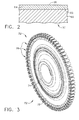
- FIG. 3 shows a turbine disk 32 having an inner generally circular hub portion indicated as 74 and an outer generally circular perimeter or diameter indicated as 78, and a periphery indicated as 82 that is provided with a plurality of circumferentially spaced slots indicated as 86 for receiving the root portion of turbine blades such as 38, 42. While the corrosion resistant coating 64 may be applied to the entire surface of disk 70, it is typically needed only on the surface of outer diameter 78, as well as blade slots 86.
- Coating 64 may be formed as a single layer, or may be formed as a plurality of layers. In forming a plurality of layers in coating 64, each respective layer may be formed by depositing a coating composition and then curing the deposited composition, with the layers being built up by depositing new portions of a coating composition on the underlying layer that was previously formed. A least one of the layers comprising coating 64 is formed from embodiments of the corrosion resistant coating composition of this invention and is adjacent to metal substrate 60, with other layers being formed from embodiments of the corrosion resistant coating composition of this invention or from other coating compositions. The respective layers of coating 64 may have the same or differing thicknesses.
- coating 64 comprises a plurality of layers
- these layers typically tend to decrease in thickness in the direction from the inner layers (i.e., those closer to substrate 60) to the outer layers (i.e., those layers further away from substrate 60).
- the coating composition used in forming each of the respective layers may have the same or differing levels of particulate component and glass-forming binder component, as well as the same or differing types of particulates in the particulate component.
- the coating composition used in forming each of the respective layers may also have the same or a differing binder component, for example, magnesium phosphate in the inner layers and aluminum phosphate in the outer layers.
- the level of particulates in the particulate component of the coating composition may differ in the respective layers, and typically increases from the inner layers to the outer layers.
- the inner layer or layers adjacent to the metal substrate may be formed from embodiments of the corrosion resistant coating compositions of this invention that comprise a higher level or amount of corrosion resistant particulates (e.g., yttria-stabilized zirconia or hafnia particulates) having a higher CTEs with a better CTE match with the metal substrate, while the outer layer or layers not adjacent to the metal substrate may comprise a higher level or amount of corrosion resistant particulates (e.g., alumina particulates) having lower CTEs.
- a higher level or amount of corrosion resistant particulates e.g., yttria-stabilized zirconia or hafnia particulates
- the outer layer or layers not adjacent to the metal substrate may comprise a higher level or amount of corrosion resistant particulates (e.g., alumina particulates) having lower CTEs.
- an outer glassy sealant layer may be formed for coating 64 by depositing and curing a composition that is similar to or consists essentially of a glass-forming binder component that is substantially free of the particulate component, e.g., a sealant composition.
- a sealant composition e.g., a sealant composition.
- Such outer glassy sealant layers may be formed from commercially available sealant products, for example, Alseal 598 (from Coatings for Industry, Inc.),
- SermaSeal TCS or SermaSeal 570A from Sermatech International, etc.
- FIG. 4 An embodiment of a corrosion resistant coating of this invention comprising a plurality of layers is shown in FIG. 4 and is indicated generally as 164.
- coating 164 comprises an inner layer 168 that is adjacent to and overlaying metal substrate 60, and is formed from a corrosion resistant coating composition of this invention.
- Inner layer 168 is relatively thick and typically comprises from about 10 to about 90%, more typically from about 25 to about 75%, of the total coating thickness.
- the particulate component comprising inner layer 168 also typically has a greater level or amount of particulates having higher CTE values to provide a better CTE match with substrate 60.
- Coating 164 also comprises an intermediate layer indicated generally as 172 adjacent to and overlaying inner layer 168.
- Intermediate layer 172 may be relatively thinner, especially relative to inner layer 168.
- Intermediate layer 172 typically comprises from about 10 to about 90%, more typically from about 25 to about 75%, of the total coating thickness.
- the particulate component of intermediate layer 172 can also comprise an increased amount or level of particulates having lower CTE values than that present in inner layer 168 because there is less of a need for a CTE match with inner layer 168.
- coating 164 may further comprise an outer layer indicated generally as 176 adjacent to and overlaying intermediate layer 172.
- This outer layer 176 can comprise a particulate component, but is typically substantially free of particulates.
- outer layer 176 is formed from a sealant composition or a composition that consists essentially of, or entirely of, a glass-forming binder component (i.e., is substantially free of particulates) to form a glassy outer sealant layer.
- Outer layer 176 is also typically the thinnest layer of coating 164, especially when substantially free of particulates.
- outer layer 176 has a thickness of from about 0.01 to about 1 mils (from about 0.3 to about 25.4 microns), more typically from about 0.05 to about 0.5 mils (from about 1.3 to about 12.7 microns).
- this invention can be used to form corrosion resistant coatings, as described above, on the surfaces of various other turbine engine rotor components, including turbine shafts and seals, exposed to oxygen and other corrosive elements at elevated temperatures, turbine components comprising airfoils, for example turbine blades and vanes, etc.
- the corrosion resistant coatings of various embodiments of this invention can also be applied during original manufacture of the component (i.e., an OEM component), after the component has been in operation for a period of time, after other coatings have been removed from the component (e.g., a repair situation), while the component is assembled or after the component is disassembled, etc.
Landscapes
- Chemical & Material Sciences (AREA)
- Engineering & Computer Science (AREA)
- Materials Engineering (AREA)
- Organic Chemistry (AREA)
- Chemical Kinetics & Catalysis (AREA)
- General Chemical & Material Sciences (AREA)
- Life Sciences & Earth Sciences (AREA)
- Geochemistry & Mineralogy (AREA)
- Mechanical Engineering (AREA)
- Metallurgy (AREA)
- Other Surface Treatments For Metallic Materials (AREA)
- Paints Or Removers (AREA)
Applications Claiming Priority (1)
| Application Number | Priority Date | Filing Date | Title |
|---|---|---|---|
| US11/311,137 US7604867B2 (en) | 2005-12-20 | 2005-12-20 | Particulate corrosion resistant coating composition, coated turbine component and method for coating same |
Publications (1)
| Publication Number | Publication Date |
|---|---|
| EP1801083A1 true EP1801083A1 (de) | 2007-06-27 |
Family
ID=37890266
Family Applications (1)
| Application Number | Title | Priority Date | Filing Date |
|---|---|---|---|
| EP06126604A Ceased EP1801083A1 (de) | 2005-12-20 | 2006-12-20 | Partikelförmige, korrosionsfeste Beschichtungszusammensetzung, beschichtete Turbinenkomponente und Beschichtungsverfahren dafür |
Country Status (2)
| Country | Link |
|---|---|
| US (2) | US7604867B2 (de) |
| EP (1) | EP1801083A1 (de) |
Cited By (3)
| Publication number | Priority date | Publication date | Assignee | Title |
|---|---|---|---|---|
| WO2011041027A1 (en) * | 2009-09-30 | 2011-04-07 | General Electric Company | Method for making strain tolerant corrosion protective coating compositions and coated articles |
| CN110835755A (zh) * | 2019-11-12 | 2020-02-25 | 中北大学 | 一种核用锆合金涂层的制备方法 |
| WO2020226649A1 (en) * | 2019-05-08 | 2020-11-12 | Praxair S.T. Technology, Inc. | Chromate-free ceramic coating compositions for hot corrosion protection of superalloy substrates |
Families Citing this family (17)
| Publication number | Priority date | Publication date | Assignee | Title |
|---|---|---|---|---|
| US8883261B2 (en) | 2007-12-21 | 2014-11-11 | United Technologies Corporation | Artifacts, method of creating such artifacts and methods of using such artifacts |
| KR101247481B1 (ko) * | 2008-06-20 | 2013-03-29 | 신닛테츠스미킨 카부시키카이샤 | 무방향성 전자기 강판 및 그 제조 방법 |
| US8708659B2 (en) | 2010-09-24 | 2014-04-29 | United Technologies Corporation | Turbine engine component having protective coating |
| US9598775B2 (en) * | 2011-06-13 | 2017-03-21 | Praxair S.T. Technology, Inc. | Multilayer overlay system for thermal and corrosion protection of superalloy substrates |
| BR112014015249B1 (pt) * | 2011-12-19 | 2021-04-13 | Praxair S.T. Technology, Inc | Composição de pasta fluida aquosa |
| WO2013116349A1 (en) * | 2012-01-30 | 2013-08-08 | United Technologies Corporation | Artifacts, methods of creating such artifacts and methods of using such artifacts |
| US9822258B2 (en) * | 2012-04-03 | 2017-11-21 | MTU Aero Engines AG | Cr(VI)-free corrosion protection layers or adhesion promoter layers produced using a solution comprising phosphate ions and metal powder, wherein the metal powder is coated at least partly with Si or Si alloys |
| CA2904185C (en) | 2013-03-13 | 2021-02-23 | General Electric Company | Coatings for metallic substrates |
| US9896585B2 (en) * | 2014-10-08 | 2018-02-20 | General Electric Company | Coating, coating system, and coating method |
| US10280770B2 (en) * | 2014-10-09 | 2019-05-07 | Rolls-Royce Corporation | Coating system including oxide nanoparticles in oxide matrix |
| DE102015107171A1 (de) * | 2015-05-07 | 2016-11-10 | Nemak, S.A.B. De C.V. | Metallteil und Verfahren zu seiner Herstellung |
| US10794221B2 (en) * | 2017-04-25 | 2020-10-06 | United Technologies Corporation | Gas turbine engine with geopolymer seal element |
| CN108793743A (zh) * | 2017-04-28 | 2018-11-13 | 李超凡 | 一种用于船体金属外表面防腐的釉料及其烧结工艺 |
| FR3088564B1 (fr) * | 2018-11-16 | 2020-12-25 | Safran Aircraft Engines | Procede de compactage d'une peinture anti-corrosion d'une piece de turbomachine |
| WO2020191363A1 (en) * | 2019-03-21 | 2020-09-24 | University Of Connecticut | Coated combustion component from liquid precursor thermal spraying |
| FR3102694B1 (fr) | 2019-10-30 | 2022-06-03 | Safran Aircraft Engines | Procede de compactage d’un revetement anti-corrosion |
| US12252628B2 (en) * | 2020-11-06 | 2025-03-18 | Praxair S.T. Technology, Inc. | Chromate-free inorganic coating systems for hot corrosion protection of superalloy substrate |
Citations (13)
| Publication number | Priority date | Publication date | Assignee | Title |
|---|---|---|---|---|
| US3179524A (en) * | 1959-10-30 | 1965-04-20 | Artrite Resins Ltd | Inorganic co-polymeric materials and process |
| GB2127396A (en) * | 1982-09-23 | 1984-04-11 | Us Energy | Magnesium phosphate composition |
| EP0132078A2 (de) * | 1983-07-19 | 1985-01-23 | Imperial Chemical Industries Plc | Zusammensetzungen zum Überziehen oder Giessen |
| DE3403660A1 (de) * | 1984-02-03 | 1985-08-08 | Joachim Dr. 4330 Mülheim Marx | Mittel zur herstellung von schutzschichten |
| EP0751104A2 (de) * | 1995-06-29 | 1997-01-02 | ROLLS-ROYCE plc | Verschleisszusammensetzung, verfahren zur Herstellung einer Verschleisszusammensetzung und gasturbine Motor mit Verschleissdichtung |
| WO1999048837A1 (en) * | 1998-03-27 | 1999-09-30 | Siemens Westinghouse Power Corporation | Use of high temperature insulation for ceramic matrix composites in gas turbines |
| US6007919A (en) * | 1998-12-22 | 1999-12-28 | General Electric Company | High temperature high band heat reflecting coating material and coated article |
| WO2000052307A1 (en) * | 1999-03-03 | 2000-09-08 | Siemens Westinghouse Power Corporation | High temperature erosion resistant, abradable thermal barrier composite coating |
| WO2001046084A1 (en) * | 1999-12-20 | 2001-06-28 | Siemens Westinghouse Power Corporation | High temperature erosion resistant coating and material containing compacted hollow geometric shapes |
| WO2002018674A2 (en) * | 2000-08-31 | 2002-03-07 | Siemens Westinghouse Power Corporation | Thermal barrier coating system for turbine components |
| EP1394139A2 (de) * | 2002-08-08 | 2004-03-03 | Siemens Westinghouse Power Corporation | Schutzbeschichtung für Keramik |
| EP1553145A1 (de) * | 2003-12-29 | 2005-07-13 | General Electric Company | Nachbesserung von Mehrschicht-Oxidelack in Gasturbinen-Scheiben und Dichtungen |
| EP1672174A1 (de) * | 2004-12-15 | 2006-06-21 | General Electric Company | Zusammensetzung einer korrosionsbeständigen Schicht, ein beschichtetes Turbinenteil und Verfahren zur dessen Beschichtung. |
Family Cites Families (30)
| Publication number | Priority date | Publication date | Assignee | Title |
|---|---|---|---|---|
| US4564555A (en) * | 1982-10-27 | 1986-01-14 | Sermatech International Incorporated | Coated part, coating therefor and method of forming same |
| US4606967A (en) * | 1983-10-19 | 1986-08-19 | Sermatech International Inc. | Spherical aluminum particles in coatings |
| US4537632A (en) * | 1983-10-19 | 1985-08-27 | Sermatech International, Inc. | Spherical aluminum particles in coatings |
| US4975330A (en) * | 1983-11-28 | 1990-12-04 | Sermatech International, Inc. | Coating compositions containing unreacted hexavalent chromium, a method of applying and an article |
| US4889558A (en) | 1983-11-28 | 1989-12-26 | Sermatech International, Inc. | Coating compositions containing undissolved hexavalent chromium salt |
| US4617056A (en) * | 1983-12-29 | 1986-10-14 | Sermatech International, Inc. | Thick coating compositions |
| US4917960A (en) * | 1983-12-29 | 1990-04-17 | Sermatech International, Inc. | Porous coated product |
| US4659613A (en) * | 1983-12-29 | 1987-04-21 | Sermatech International, Inc. | Parts coated with thick coating compositions of uni- and polymodal types |
| US4724172A (en) * | 1983-12-29 | 1988-02-09 | Sermatech International, Inc. | Thick coating compositions |
| EP0187612B1 (de) * | 1984-12-24 | 1990-09-12 | United Technologies Corporation | Abschleifbare Dichtung mit besonderem Erosionswiderstand |
| JPH0560831B1 (de) * | 1986-06-17 | 1993-09-03 | Dainippon Pharmaceutical Co | |
| US5066540A (en) * | 1987-01-23 | 1991-11-19 | Sermatech International, Inc. | Flake materials in coating compositions |
| US4863516A (en) * | 1987-01-23 | 1989-09-05 | Sermatech International, Inc. | Coating composition |
| US4806161A (en) * | 1987-12-04 | 1989-02-21 | Teleflex Incorporated | Coating compositions |
| US5336560A (en) * | 1991-12-20 | 1994-08-09 | United Technologies Corporation | Gas turbine elements bearing alumina-silica coating to inhibit coking |
| US5591380A (en) * | 1991-12-20 | 1997-01-07 | United Technologies Corporation | Preparation of alumina-silica sol gel compositions |
| US5242488A (en) * | 1992-06-01 | 1993-09-07 | Solar Turbines Incorporated | Coating composition and method of forming |
| US5478413A (en) * | 1994-12-27 | 1995-12-26 | Sermatech International, Inc. | Environmentally friendly coating compositions |
| US6210791B1 (en) * | 1995-11-30 | 2001-04-03 | General Electric Company | Article with a diffuse reflective barrier coating and a low-emissity coating thereon, and its preparation |
| US6465090B1 (en) * | 1995-11-30 | 2002-10-15 | General Electric Company | Protective coating for thermal barrier coatings and coating method therefor |
| JP3744680B2 (ja) * | 1998-03-31 | 2006-02-15 | 富士通株式会社 | 電源装置、および電源回路の制御方法 |
| US6177186B1 (en) | 1999-04-30 | 2001-01-23 | General Electric Company | Heat reflective, erosion and wear resistant coating mixture, method and coated article |
| US6368394B1 (en) * | 1999-10-18 | 2002-04-09 | Sermatech International, Inc. | Chromate-free phosphate bonding composition |
| KR100618742B1 (ko) * | 2001-02-02 | 2006-08-31 | 디에스엠 아이피 어셋츠 비.브이. | 1,3-디케톤의 정제 방법 |
| US6544351B2 (en) * | 2001-07-12 | 2003-04-08 | General Electric Company | Compositions and methods for producing coatings with improved surface smoothness and articles having such coatings |
| US6884470B2 (en) | 2002-10-03 | 2005-04-26 | General Electric Company | Application method for abradable material |
| US6884460B2 (en) * | 2002-12-20 | 2005-04-26 | General Electric Company | Combustion liner with heat rejection coats |
| US7270852B2 (en) * | 2003-08-04 | 2007-09-18 | General Electric Company | Aluminizing slurry compositions free of hexavalent chromium, and related methods and articles |
| US6827969B1 (en) * | 2003-12-12 | 2004-12-07 | General Electric Company | Field repairable high temperature smooth wear coating |
| US7311940B2 (en) * | 2005-11-04 | 2007-12-25 | General Electric Company | Layered paint coating for turbine blade environmental protection |
-
2005
- 2005-12-20 US US11/311,137 patent/US7604867B2/en active Active
-
2006
- 2006-12-20 EP EP06126604A patent/EP1801083A1/de not_active Ceased
-
2009
- 2009-09-18 US US12/562,611 patent/US7776143B2/en not_active Expired - Fee Related
Patent Citations (13)
| Publication number | Priority date | Publication date | Assignee | Title |
|---|---|---|---|---|
| US3179524A (en) * | 1959-10-30 | 1965-04-20 | Artrite Resins Ltd | Inorganic co-polymeric materials and process |
| GB2127396A (en) * | 1982-09-23 | 1984-04-11 | Us Energy | Magnesium phosphate composition |
| EP0132078A2 (de) * | 1983-07-19 | 1985-01-23 | Imperial Chemical Industries Plc | Zusammensetzungen zum Überziehen oder Giessen |
| DE3403660A1 (de) * | 1984-02-03 | 1985-08-08 | Joachim Dr. 4330 Mülheim Marx | Mittel zur herstellung von schutzschichten |
| EP0751104A2 (de) * | 1995-06-29 | 1997-01-02 | ROLLS-ROYCE plc | Verschleisszusammensetzung, verfahren zur Herstellung einer Verschleisszusammensetzung und gasturbine Motor mit Verschleissdichtung |
| WO1999048837A1 (en) * | 1998-03-27 | 1999-09-30 | Siemens Westinghouse Power Corporation | Use of high temperature insulation for ceramic matrix composites in gas turbines |
| US6007919A (en) * | 1998-12-22 | 1999-12-28 | General Electric Company | High temperature high band heat reflecting coating material and coated article |
| WO2000052307A1 (en) * | 1999-03-03 | 2000-09-08 | Siemens Westinghouse Power Corporation | High temperature erosion resistant, abradable thermal barrier composite coating |
| WO2001046084A1 (en) * | 1999-12-20 | 2001-06-28 | Siemens Westinghouse Power Corporation | High temperature erosion resistant coating and material containing compacted hollow geometric shapes |
| WO2002018674A2 (en) * | 2000-08-31 | 2002-03-07 | Siemens Westinghouse Power Corporation | Thermal barrier coating system for turbine components |
| EP1394139A2 (de) * | 2002-08-08 | 2004-03-03 | Siemens Westinghouse Power Corporation | Schutzbeschichtung für Keramik |
| EP1553145A1 (de) * | 2003-12-29 | 2005-07-13 | General Electric Company | Nachbesserung von Mehrschicht-Oxidelack in Gasturbinen-Scheiben und Dichtungen |
| EP1672174A1 (de) * | 2004-12-15 | 2006-06-21 | General Electric Company | Zusammensetzung einer korrosionsbeständigen Schicht, ein beschichtetes Turbinenteil und Verfahren zur dessen Beschichtung. |
Cited By (6)
| Publication number | Priority date | Publication date | Assignee | Title |
|---|---|---|---|---|
| WO2011041027A1 (en) * | 2009-09-30 | 2011-04-07 | General Electric Company | Method for making strain tolerant corrosion protective coating compositions and coated articles |
| WO2020226649A1 (en) * | 2019-05-08 | 2020-11-12 | Praxair S.T. Technology, Inc. | Chromate-free ceramic coating compositions for hot corrosion protection of superalloy substrates |
| KR20220003613A (ko) * | 2019-05-08 | 2022-01-10 | 프랙스에어 에스.티. 테크놀로지, 인코포레이티드 | 초합금 기재의 고온 부식 방지를 위한 크로메이트-무함유 세라믹 코팅 조성물 |
| US11535560B2 (en) | 2019-05-08 | 2022-12-27 | Praxair S.T. Technology, Inc. | Chromate-free ceramic coating compositions for hot corrosion protection of superalloy substrates |
| KR102796087B1 (ko) | 2019-05-08 | 2025-04-17 | 프랙스에어 에스.티. 테크놀로지, 인코포레이티드 | 초합금 기재의 고온 부식 방지를 위한 크로메이트-무함유 세라믹 코팅 조성물 |
| CN110835755A (zh) * | 2019-11-12 | 2020-02-25 | 中北大学 | 一种核用锆合金涂层的制备方法 |
Also Published As
| Publication number | Publication date |
|---|---|
| US20100006001A1 (en) | 2010-01-14 |
| US7604867B2 (en) | 2009-10-20 |
| US7776143B2 (en) | 2010-08-17 |
| US20070141371A1 (en) | 2007-06-21 |
Similar Documents
| Publication | Publication Date | Title |
|---|---|---|
| US7776143B2 (en) | Particulate corrosion resistant coating composition | |
| US7314674B2 (en) | Corrosion resistant coating composition, coated turbine component and method for coating same | |
| US20090047135A1 (en) | Layered corrosion resistant coating for turbine blade environmental protection | |
| US7666515B2 (en) | Turbine component other than airfoil having ceramic corrosion resistant coating and methods for making same | |
| US7993759B2 (en) | Corrosion coating for turbine blade environmental protection | |
| EP1798311B1 (de) | Dehnungstolerante Korrosionschutzschicht | |
| EP2053141B1 (de) | Schutzbeschichtung auf Basis von Aluminiumoxid für Wärmedämmbeschichtungen und Verfahren zum Aufbringen | |
| EP1595977B1 (de) | Werkstück aus einer Superlegierung mit einer korrosionsbeständigen Beschichtung | |
| EP1870493A2 (de) | Dehnungstolerante Beschichtung zu Umweltschutzzwecken | |
| EP1793015A2 (de) | Keramische Korrosionsschutzbeschichtung und Verfahren zum Aufbringen | |
| EP1939325A2 (de) | Dehnungstolerante Korrosionsschutzschicht und Bandverfahren zum Auftragen | |
| US20150247245A1 (en) | Protective coating systems for gas turbine engine applications and methods for fabricating the same | |
| EP1752559A2 (de) | Verfahren zum Wiederherstellen von Teilen einer Turbine | |
| EP3613869A1 (de) | Abreibbare beschichtung für bauteile in mechanischen hochtemperatursystemen | |
| US20230101282A1 (en) | Anti-corrosion coatings | |
| US20250257694A1 (en) | Gas turbine engine | |
| WO2018160195A1 (en) | Protective oxide coating for a thermal barrier coating formed from particles having a metal oxide core and an oxidizable metal shell |
Legal Events
| Date | Code | Title | Description |
|---|---|---|---|
| PUAI | Public reference made under article 153(3) epc to a published international application that has entered the european phase |
Free format text: ORIGINAL CODE: 0009012 |
|
| AK | Designated contracting states |
Kind code of ref document: A1 Designated state(s): AT BE BG CH CY CZ DE DK EE ES FI FR GB GR HU IE IS IT LI LT LU LV MC NL PL PT RO SE SI SK TR |
|
| AX | Request for extension of the european patent |
Extension state: AL BA HR MK YU |
|
| RAP1 | Party data changed (applicant data changed or rights of an application transferred) |
Owner name: GENERAL ELECTRIC COMPANY |
|
| 17P | Request for examination filed |
Effective date: 20071227 |
|
| AKX | Designation fees paid |
Designated state(s): DE FR GB |
|
| 17Q | First examination report despatched |
Effective date: 20080213 |
|
| APBK | Appeal reference recorded |
Free format text: ORIGINAL CODE: EPIDOSNREFNE |
|
| APBN | Date of receipt of notice of appeal recorded |
Free format text: ORIGINAL CODE: EPIDOSNNOA2E |
|
| APBR | Date of receipt of statement of grounds of appeal recorded |
Free format text: ORIGINAL CODE: EPIDOSNNOA3E |
|
| APAF | Appeal reference modified |
Free format text: ORIGINAL CODE: EPIDOSCREFNE |
|
| APBX | Invitation to file observations in appeal sent |
Free format text: ORIGINAL CODE: EPIDOSNOBA2E |
|
| APBT | Appeal procedure closed |
Free format text: ORIGINAL CODE: EPIDOSNNOA9E |
|
| STAA | Information on the status of an ep patent application or granted ep patent |
Free format text: STATUS: THE APPLICATION HAS BEEN REFUSED |
|
| 18R | Application refused |
Effective date: 20160830 |