EP1801339A2 - Entraînement pour actionner un battant mobile, particulièrement pour une porte ou une fenêtre - Google Patents
Entraînement pour actionner un battant mobile, particulièrement pour une porte ou une fenêtre Download PDFInfo
- Publication number
- EP1801339A2 EP1801339A2 EP06126296A EP06126296A EP1801339A2 EP 1801339 A2 EP1801339 A2 EP 1801339A2 EP 06126296 A EP06126296 A EP 06126296A EP 06126296 A EP06126296 A EP 06126296A EP 1801339 A2 EP1801339 A2 EP 1801339A2
- Authority
- EP
- European Patent Office
- Prior art keywords
- drive
- base
- housing
- base profile
- profile
- Prior art date
- Legal status (The legal status is an assumption and is not a legal conclusion. Google has not performed a legal analysis and makes no representation as to the accuracy of the status listed.)
- Granted
Links
Images




Classifications
-
- E—FIXED CONSTRUCTIONS
- E05—LOCKS; KEYS; WINDOW OR DOOR FITTINGS; SAFES
- E05F—DEVICES FOR MOVING WINGS INTO OPEN OR CLOSED POSITION; CHECKS FOR WINGS; WING FITTINGS NOT OTHERWISE PROVIDED FOR, CONCERNED WITH THE FUNCTIONING OF THE WING
- E05F15/00—Power-operated mechanisms for wings
- E05F15/60—Power-operated mechanisms for wings using electrical actuators
- E05F15/603—Power-operated mechanisms for wings using electrical actuators using rotary electromotors
-
- E—FIXED CONSTRUCTIONS
- E05—LOCKS; KEYS; WINDOW OR DOOR FITTINGS; SAFES
- E05F—DEVICES FOR MOVING WINGS INTO OPEN OR CLOSED POSITION; CHECKS FOR WINGS; WING FITTINGS NOT OTHERWISE PROVIDED FOR, CONCERNED WITH THE FUNCTIONING OF THE WING
- E05F15/00—Power-operated mechanisms for wings
- E05F15/60—Power-operated mechanisms for wings using electrical actuators
- E05F15/603—Power-operated mechanisms for wings using electrical actuators using rotary electromotors
- E05F15/611—Power-operated mechanisms for wings using electrical actuators using rotary electromotors for swinging wings
- E05F15/63—Power-operated mechanisms for wings using electrical actuators using rotary electromotors for swinging wings operated by swinging arms
-
- E—FIXED CONSTRUCTIONS
- E05—LOCKS; KEYS; WINDOW OR DOOR FITTINGS; SAFES
- E05F—DEVICES FOR MOVING WINGS INTO OPEN OR CLOSED POSITION; CHECKS FOR WINGS; WING FITTINGS NOT OTHERWISE PROVIDED FOR, CONCERNED WITH THE FUNCTIONING OF THE WING
- E05F15/00—Power-operated mechanisms for wings
- E05F15/60—Power-operated mechanisms for wings using electrical actuators
- E05F15/603—Power-operated mechanisms for wings using electrical actuators using rotary electromotors
- E05F15/632—Power-operated mechanisms for wings using electrical actuators using rotary electromotors for horizontally-sliding wings
-
- E—FIXED CONSTRUCTIONS
- E05—LOCKS; KEYS; WINDOW OR DOOR FITTINGS; SAFES
- E05F—DEVICES FOR MOVING WINGS INTO OPEN OR CLOSED POSITION; CHECKS FOR WINGS; WING FITTINGS NOT OTHERWISE PROVIDED FOR, CONCERNED WITH THE FUNCTIONING OF THE WING
- E05F15/00—Power-operated mechanisms for wings
- E05F15/60—Power-operated mechanisms for wings using electrical actuators
- E05F15/603—Power-operated mechanisms for wings using electrical actuators using rotary electromotors
- E05F15/632—Power-operated mechanisms for wings using electrical actuators using rotary electromotors for horizontally-sliding wings
- E05F15/643—Power-operated mechanisms for wings using electrical actuators using rotary electromotors for horizontally-sliding wings operated by flexible elongated pulling elements, e.g. belts, chains or cables
-
- E—FIXED CONSTRUCTIONS
- E05—LOCKS; KEYS; WINDOW OR DOOR FITTINGS; SAFES
- E05Y—INDEXING SCHEME ASSOCIATED WITH SUBCLASSES E05D AND E05F, RELATING TO CONSTRUCTION ELEMENTS, ELECTRIC CONTROL, POWER SUPPLY, POWER SIGNAL OR TRANSMISSION, USER INTERFACES, MOUNTING OR COUPLING, DETAILS, ACCESSORIES, AUXILIARY OPERATIONS NOT OTHERWISE PROVIDED FOR, APPLICATION THEREOF
- E05Y2800/00—Details, accessories and auxiliary operations not otherwise provided for
- E05Y2800/15—Applicability
- E05Y2800/16—Applicable on combinations of fixed and movable wings
-
- E—FIXED CONSTRUCTIONS
- E05—LOCKS; KEYS; WINDOW OR DOOR FITTINGS; SAFES
- E05Y—INDEXING SCHEME ASSOCIATED WITH SUBCLASSES E05D AND E05F, RELATING TO CONSTRUCTION ELEMENTS, ELECTRIC CONTROL, POWER SUPPLY, POWER SIGNAL OR TRANSMISSION, USER INTERFACES, MOUNTING OR COUPLING, DETAILS, ACCESSORIES, AUXILIARY OPERATIONS NOT OTHERWISE PROVIDED FOR, APPLICATION THEREOF
- E05Y2800/00—Details, accessories and auxiliary operations not otherwise provided for
- E05Y2800/72—Sets of mutually exchangeable elements, e.g. modular
-
- E—FIXED CONSTRUCTIONS
- E05—LOCKS; KEYS; WINDOW OR DOOR FITTINGS; SAFES
- E05Y—INDEXING SCHEME ASSOCIATED WITH SUBCLASSES E05D AND E05F, RELATING TO CONSTRUCTION ELEMENTS, ELECTRIC CONTROL, POWER SUPPLY, POWER SIGNAL OR TRANSMISSION, USER INTERFACES, MOUNTING OR COUPLING, DETAILS, ACCESSORIES, AUXILIARY OPERATIONS NOT OTHERWISE PROVIDED FOR, APPLICATION THEREOF
- E05Y2900/00—Application of doors, windows, wings or fittings thereof
- E05Y2900/10—Application of doors, windows, wings or fittings thereof for buildings or parts thereof
- E05Y2900/13—Type of wing
- E05Y2900/132—Doors
Definitions
- the invention relates to a drive for actuating a movable wing, in particular a door or a window, according to the preamble of patent claim 1.
- the drive has a basic profile. At least one drive component, which is designed for example as a drive motor, can be arranged on the base profile by the drive component is mechanically connected to a receiving area of the base profile.
- the receiving area of the base profile is designed as a slot formed on the profile, in which the drive component can be clamped by means of a clamping screw connection.
- the electrical connection of the drive component with other drive components is done separately, for example via a separately to be laid and connected line. Making the mechanical clamp connection as well as the separate electrical connection for each individual drive component during assembly of the drive or during component replacement as part of repairs is time-consuming. Furthermore, tools for producing the mechanical and - if available - the electrical connection are needed.
- the invention has for its object to further develop a drive of the generic type so that the installation and repair costs are significantly reduced.
- the base profile has at least one preassembled, electrical line device, wherein the receiving region of the base profile is designed such that the electrical connection can also be produced when the mechanical connection between the drive component and the base profile is established.
- At least one electrical connection can be arranged in the receiving region of the base profile.
- the electrical connection can be designed as a multi-pole plug or socket, which can be electrically connected to other electrical connections by a factory pre-assembled, electrical line device.
- the line device in the base profile factory-laid busbars which are accessible in the region of the electrical connection.
- the receiving region of the base profile can be designed so that the mechanical connection between the drive component and the base profile can be produced by inserting the drive component into the receiving region and subsequent latching.
- the receiving area of the basic profile can comprise at least one latching device, e.g. have a latching tongue, which can be manually releasable.
- the drive component to be mounted may be of modular design, ie the drive component may be selectable from a plurality of alternatively available drive components of different characteristics in order to operate with the same basic profile to realize a variety of different types and types of drive can.
- the available, selectable drive components of different characteristics each have identical mechanical and possibly electrical connections to the receiving area of the base profile, ie a replacement of a drive component against another drive component with different characteristics is by simply removing the original drive component by loosening the locking device and subsequent Tool-free mounting of the new drive component on the same receiving area of the basic profile possible.
- the housing of the drive can consist of a base housing and a housing cover.
- the basic housing can accommodate the basic profile or be formed integrally with the basic profile.
- the housing cover may be pivotally mounted on the base housing via a hinge.
- the joint is formed as a film hinge, i.
- the basic housing and the housing cover are a single, common molded part.
- the housing cover may be f- xierbar via a locking connection to the base housing.
- the release of this locking connection can be made without tools, for example, by a latching tongue is formed on the housing, which is manually releasable.
- a latching tongue is formed on the housing, which is manually releasable.
- other, not manually releasable attachment types of the housing cover may be provided on the base housing.
- FIG. 1 shows a door system 1 designed as a double-leaf automatic sliding door system.
- the door system 1 has two door panels 3 designed as sliding panels and two fixed panels 4.
- the door leaves 3 are ve r-slidably guided on a rail 6 and are driven by a arranged above the door leaves 3 drive 2.
- the drive 2 and the rail 6 are hidden behind a cover.
- Fig. 2 the door system 1 without the filler panel is shown schematically (not to scale).
- the arranged in a housing 5 drive 2 is mounted centrally above the two door leaves 3.
- the rail 6, in which the roller carriage 7 of the door leaves 3 are guided displaceably, is formed by two track elements, which I connect on both sides of the drive 2 and extend over the remaining width of the door system 1.
- Fig. 3 is designed as a single-wing, automatic revolving door system
- Door system 1 shown with a hinged to a frame 14 via hinges 15 door 3.
- the door leaf 3 is drivable by means of the drive 2 between a closed and an open position.
- the drive housing 5 of the drive 2 is fixedly mounted on the frame 14 and takes the drive components of the drive 2.
- the drive 2 has a drive motor 19, whose motor shaft 20 is connected to the shaft of a transmission 21.
- the gear 21, which is formed in this embodiment as an angle gear, has a further shaft which is connected to the output shaft 11 of the drive 2.
- a rotational movement of the output shaft 11 is converted into a pivoting movement of the door leaf 3, wherein the drive of the drive motor 19 via a controller 22 takes place.
- the drive 2 shown in the sliding door system according to FIG. 2 can also be used in the revolving door system according to FIG. 3, and vice versa.
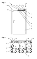
- the structure of this drive 2 is shown schematically in the following FIGS. 4 to 8:
- the base housing 34 has a base profile 23, in which various receiving areas 24 are located for the drive components. Each receiving area 24 is delimited by a plurality of latching tongues 25, which serve to lock the drive components to the basic profile 23. Each receiving area 24 is dimensioned suitably for the drive component to be mounted, wherein the base profile 23 in the area of the receiving areas 24 can have markings, for example inscriptions and / or symbols for the drive components to be mounted. Electrical connections 26 are also provided in receiving areas 24 provided for electric drive components. These can be designed as multi-pin plug or sockets, which are electrically connected to each other by a factory pre-assembled conduit means.
- the line device may include factory-installed busbars, which are accessible in the region of the electrical connections 26 (see exemplary embodiments according to FIGS. 6 ff.).
- corresponding electrical contacts can be arranged, which cooperate with the electrical terminals 26 of the base profile 23.
- the electrical wiring or busbar device is connected to another, in the region of the outer wall connected to the base housing 34, electrical connection 27 which have an accessible from outside the base housing 34, multi-pin connector and can serve for electrical connection of the drive 2.
- this connection 27 can also have a plug or socket arranged inside the basic housing 34, which can serve for the electrical connection of further electrical devices within the housing of the drive 2.
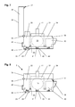
- the basic housing 34 described above is shown with now mounted on the base profile 23 drive components, with a drive motor 19 with connected gear 21, a controller 22, a transformer 28, a battery 29, a motion detector 30, a security sensor 31, an electrical lock 32 and another electrical attachment 33rd
- the drive 2 can be configured as desired by adding further drive components not mentioned here or omitting drive components and by exchanging certain drive components by other drive components.
- all available drive components are modular.
- optional drive motors 19 of different power can be mounted on the receiving area 24 provided for the drive motor 19.
- a further drive motor can be mounted, which can be mechanically coupled with the first drive motor 19, so that in this configuration a redundant, twin-motor drive 2 is present.
- a mechanical energy storage such as a spring device possible, which is mechanically coupled to the drive motor 19 or the transmission 21 and in the event of a malfunction of the drive motor 19 or the electric power supply of an emergency opening or closing the door connected to the drive 2 is used.
- a plurality of mutually mechanically independent drive motors i. be mounted with separate output shafts 11. This makes it possible, for example, to realize multi-leaf door systems with mutually independent movement of the individual door leaves.
- 6 to 8 show a side view of the mounting of the drive components in the base housing 34, wherein simplifying only a few of the drive components are shown to illustrate the mounting principle, namely the transmission 21 with drive motor 19, the controller 22 and the motion detector 30th
- a housing cover 35 is pivotally mounted via a hinge 36.
- the base housing 34 and the housing cover 35 may each be formed of plastic, wherein the gels nk 36 may be formed in this case as a film hinge.
- the housing cover 35 has on its end face facing the base housing 34 a latching tongue 37, which is latched with the housing cover 35 closed with an undercut 38 of the base housing 34.
- the latching tongue 37 may be formed so that it is tool-free, for example, by manual lifting, from the undercut 38 is releasable. Alternatively, it may be provided that the latching tongue 37 can be released exclusively by means of (special) tool.
- predetermined breaking points 39 are arranged, which can be broken if necessary, to provide recesses, which allow the passage of drive components through the walls.
- a mounting portion 40 is integrally formed, which in this embodiment as a dovetail Footbridge is formed.
- a mounting portion 40 is integrally formed, which in this embodiment as a dovetail Footbridge is formed.
- other embodiments of the attachment portion 40 are also conceivable.
- the drive can thus be arranged between the separate rails, as shown in FIG.
- the drive 2 can be fixed directly stationary in this type of mounting, the rails are in the receptacles of the base housing are stretchable, so that the images next to the fixation also serve as an assembly aid of the rails.
- each insulation body 41 are integrated in the region of the receiving areas 24, in each of which tracks of an electrical line device 42, which may be formed, for example, as a busbars are embedded.
- the number of tracks pre-assembled in the base profile 23 depends on the desired maximum configuration of the drive 2. It can be provided that the line device is part of a bus system, as a result of which the number of tracks can be considerably reduced.
- the conductor tracks are completely embedded in the insulating body 41, so that they can be contacted by piercing the insulating body 41. Alternatively, it can be provided to arrange the conductor tracks in the insulating body 41 exposed at the top.
- the drive components to be mounted which are shown separately from the base housing 34 of the drive 2 in the illustration according to FIG. 6, each have a plurality of undercuts 43 in their areas facing the base profile 23 which latch with the latching tongues 25 of the base profile 23 when the drive component is mounted are.
- the drive components to be mounted if they include electrical components, facing the base profile 23 each have contacts 44 which, when the drive component is mounted, are provided with those present in the base profile 23 electrical connections cooperate by the contacts 44 are electrically connected to the tracks of the electrical conductor means 42.
- the contacts 44 are arranged on the drive component such that they contact exactly with specific tracks when the drive component is mounted.
- the contacts 44 in the various drive components can have different arrangements, so that they make contact with different conductor tracks.
- the conductor tracks pre-mounted in the base profile 23 are each provided with multi-pole sockets or plugs in the region of the electrical connections 26, which are provided with plugs or sockets arranged on the drive components interact.
- FIGS. 6 to 8 thus schematically illustrate the extremely simple, tool-free installation of the drive components in the drive 2.
- the drive 2 described above is installed in an automatic sliding door system.
- the base housing 34 of the drive 2 is arranged by means of one of its fastening portions 40 at a stationary above the passage opening of the sliding door system mounted carrier 45 by the carrier 45 has a mounting portion 47 in the form of a dovetail groove in which the mounting portion 40 of the base housing 34 can be inserted.
- the carrier 45 of the sliding door system of this embodiment is substantially L-shaped in cross-section, the horizontal leg, as described above, the drive 2 carries and at the lower end of the vertical leg which is fixed to the wall, the rail 6 is formed , On the rail 6 roll on a rotary axis 49 on the roller carriage 7 rotatably mounted rollers 48 from. By means of a suspension is mounted on the roller carriage 7 of the door 3. On the output shaft 11 of the drive 2, a drive roller 10 is rotatably mounted, which serves for guiding and for driving a rotating drive belt 9. At the upper run of the drive belt 9 of the roller carriage 7 of the door leaf 3 is connected via a driver 50, so that caused by the drive 2 rotation of the drive roller 10 causes movement of the door leaf 3 along the rail 6.
- the movement detector 30 arranged in the basic housing 34 of the drive 2 detects movements in the area in the drawing to the left in front of the door leaf 3 and controls the drive 2 as a function thereof.
- Another, opposite, here not shown door is coupled via another driver on the lower run of the drive belt 9, so that by the opposite movement of the strands of the rotating drive belt 9, an opposite movement of the door 3 is achieved.
- a diaphragm 46 is fastened to a further fastening section 40 of the basic housing 34 of the drive 2, which diaphragm has a complementary attachment section 47 for this purpose.
- Another (not shown here) motion detector can detect the area in the drawing right in front of the door leaf 3, where it is fixedly mounted above the passage area and an electrical connection (for example, a plug contact, as shown by reference numeral 27 in Fig. 4 ) is electrically connected to the drive 2.
- an electrical connection for example, a plug contact, as shown by reference numeral 27 in Fig. 4
- other sensors such as safety sensors to secure the path of movement of the door leaf 3, which, like the motion detector 30, may be disposed within the base housing 34 and the wall by another Recess, which can be produced by a further predetermined breaking point, pass through.
- the embodiment shown in FIG. 10 differs from the embodiment described above with respect to FIG. 9 in that the drive 2 is mounted rotated by 90 ° in order to provide a so-called low-sliding door drive.
- the base housing 34 of the drive 2 is mounted by means of one of its mounting portions 40 on a complementary mounting portion 47 of the C-shaped, fixedly mounted rail 6. Due to the rotated arrangement of the drive 2, the output shaft 11 emerges from the drive 2 at the bottom with a vertical axis of rotation, so that the drive roller 10 and the circulating drive belt 9 are arranged in a horizontal plane below the drive 2.
- the right in the drawing strand of the drive belt 9 is connected via a driver 50 with the roller carriage 7, which rolls on paired rollers 48 on the running surfaces of the rail 6.
- Another, opposite, not shown here door is coupled via another driver on the left run of the drive belt 9, so that by the opposite movement of the strands of the rotating drive belt 9, an opposite movement of the door 3 is achieved.
- the movement detector 30 used in this embodiment due to the arrangement of the drive 2 rotated by 90 ° with respect to the preceding exemplary embodiment, has a different design with regard to the alignment of the detection optics in order to be able to detect the area in the drawing to the left of the door leaf 3. It is essential, however, that all motion detectors 30 available for the different types of installation of the drive 2 can be mounted without further adjustments on the same receiving area 24 of the basic profile 23.
- the drive 2 described above is installed in an automatic revolving door system.
- a support 45 is fixed in place, which has a receiving area 47 for receiving a complementarily shaped receiving area 40 of the base housing 34 of the Drive has.
- the output shaft 11 emerges with a vertical axis of rotation from the bottom of the drive 2 and is rotatably connected to one end of a force-transmitting, designed as a sliding arm 16 linkage.
- the other end of the slide arm 16 is guided by means of a slider 17 in a mounted on the door leaf 3 slide 18, so that rotation of the output shaft 11, a pivoting movement of the door leaf 3 is achieved.
Landscapes
- Power-Operated Mechanisms For Wings (AREA)
- Window Of Vehicle (AREA)
Applications Claiming Priority (1)
| Application Number | Priority Date | Filing Date | Title |
|---|---|---|---|
| DE102005061724A DE102005061724B4 (de) | 2005-12-21 | 2005-12-21 | Antrieb zum Betätigen eines beweglichen Flügels, insbesondere einer Tür oder eines Fensters |
Publications (3)
| Publication Number | Publication Date |
|---|---|
| EP1801339A2 true EP1801339A2 (fr) | 2007-06-27 |
| EP1801339A3 EP1801339A3 (fr) | 2009-01-14 |
| EP1801339B1 EP1801339B1 (fr) | 2010-07-28 |
Family
ID=37969737
Family Applications (1)
| Application Number | Title | Priority Date | Filing Date |
|---|---|---|---|
| EP06126296A Active EP1801339B1 (fr) | 2005-12-21 | 2006-12-18 | Entraînement pour actionner un battant mobile, particulièrement pour une porte ou une fenêtre |
Country Status (4)
| Country | Link |
|---|---|
| EP (1) | EP1801339B1 (fr) |
| AT (1) | ATE475771T1 (fr) |
| DE (2) | DE102005061724B4 (fr) |
| ES (1) | ES2345898T3 (fr) |
Cited By (11)
| Publication number | Priority date | Publication date | Assignee | Title |
|---|---|---|---|---|
| AT505613B1 (de) * | 2007-12-20 | 2009-03-15 | Blum Gmbh Julius | Möbelantrieb |
| EP2060722A1 (fr) * | 2007-11-13 | 2009-05-20 | Dorma GmbH + CO. KG | Entraînement de porte à construction modulaire |
| WO2009062709A1 (fr) * | 2007-11-13 | 2009-05-22 | Dorma Gmbh + Co. Kg | Mécanisme d'entraînement pour porte |
| WO2011030141A1 (fr) * | 2009-09-08 | 2011-03-17 | Fendor Limited | Mécanisme d'entraînement motorisé |
| EP2161400A3 (fr) * | 2008-09-08 | 2014-04-02 | Dorma GmbH + CO. KG | Ensemble de rééquipement doté d'une unité d'entraînement, notamment pour une porte coulissante automatique |
| US9003630B2 (en) | 2007-11-13 | 2015-04-14 | Dorma Gmbh + Co. Kg | Assembly plate for housing at least one module in a housing body and corresponding method |
| EP2209962B1 (fr) | 2007-11-13 | 2015-06-10 | DORMA Deutschland GmbH | Entraînement de porte à construction modulaire |
| DE102014115921A1 (de) * | 2014-10-31 | 2016-05-04 | Dorma Deutschland Gmbh | Türantrieb |
| EP3015634A1 (fr) * | 2014-10-31 | 2016-05-04 | DORMA Deutschland GmbH | Entrainement de porte |
| FR3043122A1 (fr) * | 2015-10-30 | 2017-05-05 | Lacroix | Dispositif et procede d'automatisation d'une porte |
| ITUB20156093A1 (it) * | 2015-12-02 | 2017-06-02 | Topp Srl A Socio Unico | Apparato di azionamento per una porta scorrevole |
Families Citing this family (3)
| Publication number | Priority date | Publication date | Assignee | Title |
|---|---|---|---|---|
| EP2141315A3 (fr) | 2008-06-30 | 2014-03-26 | GEZE GmbH | Porte, fenêtre ou analogue |
| DE102021200222B4 (de) * | 2021-01-12 | 2024-10-02 | Geze Gmbh | Antrieb für ein automatisches Schiebetürsystem |
| WO2025208132A1 (fr) * | 2024-03-29 | 2025-10-02 | Hands Free, Inc. | Système d'ouverture de porte actionné à distance |
Family Cites Families (5)
| Publication number | Priority date | Publication date | Assignee | Title |
|---|---|---|---|---|
| DE9302490U1 (de) * | 1993-02-20 | 1993-05-06 | Geze GmbH & Co, 7250 Leonberg | Automatisch angetriebene Tür- oder Fensteranlage |
| DE19809909B4 (de) * | 1998-03-07 | 2009-01-08 | Geze Gmbh | Schiene mit Stromzuführungseinrichtung |
| DE19949453B4 (de) * | 1999-09-06 | 2013-08-29 | Geze Gmbh | Automatische Tür- oder Fensteranlage |
| DE10260109B4 (de) * | 2002-12-19 | 2014-05-22 | Geze Gmbh | Schiebetüranlage |
| DE20318994U1 (de) * | 2003-12-08 | 2005-04-28 | Marantec Antriebs- Und Steuerungstechnik Gmbh & Co. Kg | Torantriebsgehäuse |
-
2005
- 2005-12-21 DE DE102005061724A patent/DE102005061724B4/de not_active Withdrawn - After Issue
-
2006
- 2006-12-18 ES ES06126296T patent/ES2345898T3/es active Active
- 2006-12-18 DE DE502006007525T patent/DE502006007525D1/de active Active
- 2006-12-18 AT AT06126296T patent/ATE475771T1/de active
- 2006-12-18 EP EP06126296A patent/EP1801339B1/fr active Active
Cited By (16)
| Publication number | Priority date | Publication date | Assignee | Title |
|---|---|---|---|---|
| EP2209962B2 (fr) † | 2007-11-13 | 2021-08-04 | DORMA Deutschland GmbH | Entraînement de porte à construction modulaire |
| EP2060722A1 (fr) * | 2007-11-13 | 2009-05-20 | Dorma GmbH + CO. KG | Entraînement de porte à construction modulaire |
| WO2009062709A1 (fr) * | 2007-11-13 | 2009-05-22 | Dorma Gmbh + Co. Kg | Mécanisme d'entraînement pour porte |
| US8695277B2 (en) | 2007-11-13 | 2014-04-15 | Dorma Gmbh + Co. Kg | Door actuator |
| US9003630B2 (en) | 2007-11-13 | 2015-04-14 | Dorma Gmbh + Co. Kg | Assembly plate for housing at least one module in a housing body and corresponding method |
| EP2209962B1 (fr) | 2007-11-13 | 2015-06-10 | DORMA Deutschland GmbH | Entraînement de porte à construction modulaire |
| WO2009079671A1 (fr) | 2007-12-20 | 2009-07-02 | Julius Blum Gmbh | Entraînement pour meuble |
| AT505613B1 (de) * | 2007-12-20 | 2009-03-15 | Blum Gmbh Julius | Möbelantrieb |
| EP2161400A3 (fr) * | 2008-09-08 | 2014-04-02 | Dorma GmbH + CO. KG | Ensemble de rééquipement doté d'une unité d'entraînement, notamment pour une porte coulissante automatique |
| WO2011030141A1 (fr) * | 2009-09-08 | 2011-03-17 | Fendor Limited | Mécanisme d'entraînement motorisé |
| EP3015634A1 (fr) * | 2014-10-31 | 2016-05-04 | DORMA Deutschland GmbH | Entrainement de porte |
| EP3015632A1 (fr) * | 2014-10-31 | 2016-05-04 | DORMA Deutschland GmbH | Entrainement de porte |
| DE102014115921A1 (de) * | 2014-10-31 | 2016-05-04 | Dorma Deutschland Gmbh | Türantrieb |
| FR3043122A1 (fr) * | 2015-10-30 | 2017-05-05 | Lacroix | Dispositif et procede d'automatisation d'une porte |
| ITUB20156093A1 (it) * | 2015-12-02 | 2017-06-02 | Topp Srl A Socio Unico | Apparato di azionamento per una porta scorrevole |
| EP3176354A1 (fr) * | 2015-12-02 | 2017-06-07 | Topp Srl a socio unico | Dispositif d'actionnement pour porte coulissante |
Also Published As
| Publication number | Publication date |
|---|---|
| DE102005061724A1 (de) | 2007-07-05 |
| DE102005061724B4 (de) | 2012-08-23 |
| EP1801339B1 (fr) | 2010-07-28 |
| ATE475771T1 (de) | 2010-08-15 |
| ES2345898T3 (es) | 2010-10-05 |
| EP1801339A3 (fr) | 2009-01-14 |
| DE502006007525D1 (de) | 2010-09-09 |
Similar Documents
| Publication | Publication Date | Title |
|---|---|---|
| DE19831774B4 (de) | Automatische Tür- oder Fensteranlage | |
| DE102008028831B4 (de) | Antriebssystem zum Antrieb und zur Führung eines Wandelementes für ein Raumtrennwandsystem | |
| DE102005053560B4 (de) | Elektromechanischer Antrieb für ein Tor oder dergleichen | |
| EP1801339B1 (fr) | Entraînement pour actionner un battant mobile, particulièrement pour une porte ou une fenêtre | |
| EP1552096B1 (fr) | Dispositif pour elements de separation coulissants, chariot et element de separation | |
| DE19949453B4 (de) | Automatische Tür- oder Fensteranlage | |
| EP0883726A1 (fr) | Systeme de porte coulissante | |
| DE102008046538B4 (de) | Antriebssystem für ein Tor | |
| EP2382365B1 (fr) | Système d'entraînement pour une porte | |
| EP1640543B1 (fr) | Dispositif de propulsion pour un élément de séparation coulissant | |
| EP1999331B2 (fr) | Ferrure | |
| EP1094186A1 (fr) | Rail avec dispositif d'alimentation de courant | |
| EP2227615B1 (fr) | Système d'entrainement pour un portail | |
| DE19942052A1 (de) | Elektrische Einrichtung in oder an einer Tür oder einem Fenster | |
| WO2002055823A1 (fr) | Commande de porte tournante electromecanique | |
| EP1612364A2 (fr) | Ensemble de porte coulissante automatique | |
| DE202012104162U1 (de) | Tür mit integriertem Linearantrieb | |
| DE19648147C1 (de) | Motorisch angetriebene Kippöffnungs-Vorrichtung für Fenster oder Türen | |
| DE102004059895A1 (de) | Elektromechanischer Antrieb für das ein- oder mehrteilige Torblatt eines Tores, z.B. eines Garagentores | |
| EP2933416A1 (fr) | Entraînement de porte | |
| DE202007015778U1 (de) | Motorisierter Antrieb an einem Deckengliedertor |
Legal Events
| Date | Code | Title | Description |
|---|---|---|---|
| PUAI | Public reference made under article 153(3) epc to a published international application that has entered the european phase |
Free format text: ORIGINAL CODE: 0009012 |
|
| AK | Designated contracting states |
Kind code of ref document: A2 Designated state(s): AT BE BG CH CY CZ DE DK EE ES FI FR GB GR HU IE IS IT LI LT LU LV MC NL PL PT RO SE SI SK TR |
|
| AX | Request for extension of the european patent |
Extension state: AL BA HR MK YU |
|
| PUAL | Search report despatched |
Free format text: ORIGINAL CODE: 0009013 |
|
| AK | Designated contracting states |
Kind code of ref document: A3 Designated state(s): AT BE BG CH CY CZ DE DK EE ES FI FR GB GR HU IE IS IT LI LT LU LV MC NL PL PT RO SE SI SK TR |
|
| AX | Request for extension of the european patent |
Extension state: AL BA HR MK RS |
|
| 17P | Request for examination filed |
Effective date: 20090710 |
|
| AKX | Designation fees paid |
Designated state(s): AT BE BG CH CY CZ DE DK EE ES FI FR GB GR HU IE IS IT LI LT LU LV MC NL PL PT RO SE SI SK TR |
|
| 17Q | First examination report despatched |
Effective date: 20090924 |
|
| GRAP | Despatch of communication of intention to grant a patent |
Free format text: ORIGINAL CODE: EPIDOSNIGR1 |
|
| GRAS | Grant fee paid |
Free format text: ORIGINAL CODE: EPIDOSNIGR3 |
|
| GRAA | (expected) grant |
Free format text: ORIGINAL CODE: 0009210 |
|
| AK | Designated contracting states |
Kind code of ref document: B1 Designated state(s): AT BE BG CH CY CZ DE DK EE ES FI FR GB GR HU IE IS IT LI LT LU LV MC NL PL PT RO SE SI SK TR |
|
| REG | Reference to a national code |
Ref country code: GB Ref legal event code: FG4D Free format text: NOT ENGLISH |
|
| REG | Reference to a national code |
Ref country code: CH Ref legal event code: EP |
|
| REG | Reference to a national code |
Ref country code: IE Ref legal event code: FG4D Free format text: LANGUAGE OF EP DOCUMENT: GERMAN |
|
| REF | Corresponds to: |
Ref document number: 502006007525 Country of ref document: DE Date of ref document: 20100909 Kind code of ref document: P |
|
| REG | Reference to a national code |
Ref country code: ES Ref legal event code: FG2A Ref document number: 2345898 Country of ref document: ES Kind code of ref document: T3 |
|
| REG | Reference to a national code |
Ref country code: SE Ref legal event code: TRGR |
|
| REG | Reference to a national code |
Ref country code: NL Ref legal event code: VDEP Effective date: 20100728 |
|
| LTIE | Lt: invalidation of european patent or patent extension |
Effective date: 20100728 |
|
| PG25 | Lapsed in a contracting state [announced via postgrant information from national office to epo] |
Ref country code: NL Free format text: LAPSE BECAUSE OF FAILURE TO SUBMIT A TRANSLATION OF THE DESCRIPTION OR TO PAY THE FEE WITHIN THE PRESCRIBED TIME-LIMIT Effective date: 20100728 Ref country code: FI Free format text: LAPSE BECAUSE OF FAILURE TO SUBMIT A TRANSLATION OF THE DESCRIPTION OR TO PAY THE FEE WITHIN THE PRESCRIBED TIME-LIMIT Effective date: 20100728 Ref country code: LT Free format text: LAPSE BECAUSE OF FAILURE TO SUBMIT A TRANSLATION OF THE DESCRIPTION OR TO PAY THE FEE WITHIN THE PRESCRIBED TIME-LIMIT Effective date: 20100728 |
|
| PG25 | Lapsed in a contracting state [announced via postgrant information from national office to epo] |
Ref country code: PT Free format text: LAPSE BECAUSE OF FAILURE TO SUBMIT A TRANSLATION OF THE DESCRIPTION OR TO PAY THE FEE WITHIN THE PRESCRIBED TIME-LIMIT Effective date: 20101129 Ref country code: IS Free format text: LAPSE BECAUSE OF FAILURE TO SUBMIT A TRANSLATION OF THE DESCRIPTION OR TO PAY THE FEE WITHIN THE PRESCRIBED TIME-LIMIT Effective date: 20101128 Ref country code: BG Free format text: LAPSE BECAUSE OF FAILURE TO SUBMIT A TRANSLATION OF THE DESCRIPTION OR TO PAY THE FEE WITHIN THE PRESCRIBED TIME-LIMIT Effective date: 20101028 Ref country code: PL Free format text: LAPSE BECAUSE OF FAILURE TO SUBMIT A TRANSLATION OF THE DESCRIPTION OR TO PAY THE FEE WITHIN THE PRESCRIBED TIME-LIMIT Effective date: 20100728 Ref country code: SI Free format text: LAPSE BECAUSE OF FAILURE TO SUBMIT A TRANSLATION OF THE DESCRIPTION OR TO PAY THE FEE WITHIN THE PRESCRIBED TIME-LIMIT Effective date: 20100728 Ref country code: CY Free format text: LAPSE BECAUSE OF FAILURE TO SUBMIT A TRANSLATION OF THE DESCRIPTION OR TO PAY THE FEE WITHIN THE PRESCRIBED TIME-LIMIT Effective date: 20100728 |
|
| REG | Reference to a national code |
Ref country code: IE Ref legal event code: FD4D |
|
| PG25 | Lapsed in a contracting state [announced via postgrant information from national office to epo] |
Ref country code: GR Free format text: LAPSE BECAUSE OF FAILURE TO SUBMIT A TRANSLATION OF THE DESCRIPTION OR TO PAY THE FEE WITHIN THE PRESCRIBED TIME-LIMIT Effective date: 20101029 Ref country code: LV Free format text: LAPSE BECAUSE OF FAILURE TO SUBMIT A TRANSLATION OF THE DESCRIPTION OR TO PAY THE FEE WITHIN THE PRESCRIBED TIME-LIMIT Effective date: 20100728 |
|
| PG25 | Lapsed in a contracting state [announced via postgrant information from national office to epo] |
Ref country code: DK Free format text: LAPSE BECAUSE OF FAILURE TO SUBMIT A TRANSLATION OF THE DESCRIPTION OR TO PAY THE FEE WITHIN THE PRESCRIBED TIME-LIMIT Effective date: 20100728 Ref country code: IE Free format text: LAPSE BECAUSE OF FAILURE TO SUBMIT A TRANSLATION OF THE DESCRIPTION OR TO PAY THE FEE WITHIN THE PRESCRIBED TIME-LIMIT Effective date: 20100728 |
|
| PG25 | Lapsed in a contracting state [announced via postgrant information from national office to epo] |
Ref country code: SK Free format text: LAPSE BECAUSE OF FAILURE TO SUBMIT A TRANSLATION OF THE DESCRIPTION OR TO PAY THE FEE WITHIN THE PRESCRIBED TIME-LIMIT Effective date: 20100728 Ref country code: RO Free format text: LAPSE BECAUSE OF FAILURE TO SUBMIT A TRANSLATION OF THE DESCRIPTION OR TO PAY THE FEE WITHIN THE PRESCRIBED TIME-LIMIT Effective date: 20100728 Ref country code: EE Free format text: LAPSE BECAUSE OF FAILURE TO SUBMIT A TRANSLATION OF THE DESCRIPTION OR TO PAY THE FEE WITHIN THE PRESCRIBED TIME-LIMIT Effective date: 20100728 Ref country code: CZ Free format text: LAPSE BECAUSE OF FAILURE TO SUBMIT A TRANSLATION OF THE DESCRIPTION OR TO PAY THE FEE WITHIN THE PRESCRIBED TIME-LIMIT Effective date: 20100728 |
|
| PLBE | No opposition filed within time limit |
Free format text: ORIGINAL CODE: 0009261 |
|
| STAA | Information on the status of an ep patent application or granted ep patent |
Free format text: STATUS: NO OPPOSITION FILED WITHIN TIME LIMIT |
|
| BERE | Be: lapsed |
Owner name: GEZE G.M.B.H. Effective date: 20101231 |
|
| 26N | No opposition filed |
Effective date: 20110429 |
|
| PG25 | Lapsed in a contracting state [announced via postgrant information from national office to epo] |
Ref country code: MC Free format text: LAPSE BECAUSE OF NON-PAYMENT OF DUE FEES Effective date: 20101231 |
|
| REG | Reference to a national code |
Ref country code: DE Ref legal event code: R097 Ref document number: 502006007525 Country of ref document: DE Effective date: 20110429 |
|
| PG25 | Lapsed in a contracting state [announced via postgrant information from national office to epo] |
Ref country code: BE Free format text: LAPSE BECAUSE OF NON-PAYMENT OF DUE FEES Effective date: 20101231 |
|
| PG25 | Lapsed in a contracting state [announced via postgrant information from national office to epo] |
Ref country code: LU Free format text: LAPSE BECAUSE OF NON-PAYMENT OF DUE FEES Effective date: 20101218 Ref country code: HU Free format text: LAPSE BECAUSE OF FAILURE TO SUBMIT A TRANSLATION OF THE DESCRIPTION OR TO PAY THE FEE WITHIN THE PRESCRIBED TIME-LIMIT Effective date: 20110129 |
|
| PG25 | Lapsed in a contracting state [announced via postgrant information from national office to epo] |
Ref country code: TR Free format text: LAPSE BECAUSE OF FAILURE TO SUBMIT A TRANSLATION OF THE DESCRIPTION OR TO PAY THE FEE WITHIN THE PRESCRIBED TIME-LIMIT Effective date: 20100728 |
|
| REG | Reference to a national code |
Ref country code: FR Ref legal event code: PLFP Year of fee payment: 10 |
|
| REG | Reference to a national code |
Ref country code: FR Ref legal event code: PLFP Year of fee payment: 11 |
|
| REG | Reference to a national code |
Ref country code: FR Ref legal event code: PLFP Year of fee payment: 12 |
|
| PGFP | Annual fee paid to national office [announced via postgrant information from national office to epo] |
Ref country code: SE Payment date: 20221222 Year of fee payment: 17 Ref country code: GB Payment date: 20221222 Year of fee payment: 17 Ref country code: FR Payment date: 20221222 Year of fee payment: 17 Ref country code: AT Payment date: 20221222 Year of fee payment: 17 |
|
| PGFP | Annual fee paid to national office [announced via postgrant information from national office to epo] |
Ref country code: ES Payment date: 20230224 Year of fee payment: 17 Ref country code: CH Payment date: 20230103 Year of fee payment: 17 |
|
| PGFP | Annual fee paid to national office [announced via postgrant information from national office to epo] |
Ref country code: IT Payment date: 20221228 Year of fee payment: 17 |
|
| PGFP | Annual fee paid to national office [announced via postgrant information from national office to epo] |
Ref country code: DE Payment date: 20231231 Year of fee payment: 18 |
|
| REG | Reference to a national code |
Ref country code: SE Ref legal event code: EUG |
|
| REG | Reference to a national code |
Ref country code: CH Ref legal event code: PL |
|
| REG | Reference to a national code |
Ref country code: AT Ref legal event code: MM01 Ref document number: 475771 Country of ref document: AT Kind code of ref document: T Effective date: 20231218 |
|
| GBPC | Gb: european patent ceased through non-payment of renewal fee |
Effective date: 20231218 |
|
| PG25 | Lapsed in a contracting state [announced via postgrant information from national office to epo] |
Ref country code: GB Free format text: LAPSE BECAUSE OF NON-PAYMENT OF DUE FEES Effective date: 20231218 |
|
| PG25 | Lapsed in a contracting state [announced via postgrant information from national office to epo] |
Ref country code: FR Free format text: LAPSE BECAUSE OF NON-PAYMENT OF DUE FEES Effective date: 20231231 |
|
| PG25 | Lapsed in a contracting state [announced via postgrant information from national office to epo] |
Ref country code: CH Free format text: LAPSE BECAUSE OF NON-PAYMENT OF DUE FEES Effective date: 20231231 |
|
| PG25 | Lapsed in a contracting state [announced via postgrant information from national office to epo] |
Ref country code: AT Free format text: LAPSE BECAUSE OF NON-PAYMENT OF DUE FEES Effective date: 20231218 |
|
| PG25 | Lapsed in a contracting state [announced via postgrant information from national office to epo] |
Ref country code: GB Free format text: LAPSE BECAUSE OF NON-PAYMENT OF DUE FEES Effective date: 20231218 Ref country code: FR Free format text: LAPSE BECAUSE OF NON-PAYMENT OF DUE FEES Effective date: 20231231 Ref country code: CH Free format text: LAPSE BECAUSE OF NON-PAYMENT OF DUE FEES Effective date: 20231231 Ref country code: AT Free format text: LAPSE BECAUSE OF NON-PAYMENT OF DUE FEES Effective date: 20231218 |
|
| P01 | Opt-out of the competence of the unified patent court (upc) registered |
Free format text: CASE NUMBER: UPC_APP_118283/2023 Effective date: 20230510 |
|
| REG | Reference to a national code |
Ref country code: DE Ref legal event code: R231 Ref document number: 502006007525 Country of ref document: DE |
|
| PG25 | Lapsed in a contracting state [announced via postgrant information from national office to epo] |
Ref country code: DE Free format text: LAPSE BECAUSE OF THE APPLICANT RENOUNCES Effective date: 20241129 |
|
| REG | Reference to a national code |
Ref country code: ES Ref legal event code: FD2A Effective date: 20250129 |
|
| PG25 | Lapsed in a contracting state [announced via postgrant information from national office to epo] |
Ref country code: DE Free format text: LAPSE BECAUSE OF THE APPLICANT RENOUNCES Effective date: 20241129 |
|
| PG25 | Lapsed in a contracting state [announced via postgrant information from national office to epo] |
Ref country code: ES Free format text: LAPSE BECAUSE OF NON-PAYMENT OF DUE FEES Effective date: 20231219 |
|
| PG25 | Lapsed in a contracting state [announced via postgrant information from national office to epo] |
Ref country code: IT Free format text: LAPSE BECAUSE OF NON-PAYMENT OF DUE FEES Effective date: 20231218 |
|
| PG25 | Lapsed in a contracting state [announced via postgrant information from national office to epo] |
Ref country code: SE Free format text: LAPSE BECAUSE OF NON-PAYMENT OF DUE FEES Effective date: 20231219 |