EP1801355B1 - Laufschaufelschloss für eine Turbomaschinenrotorscheibe - Google Patents
Laufschaufelschloss für eine Turbomaschinenrotorscheibe Download PDFInfo
- Publication number
- EP1801355B1 EP1801355B1 EP05292779.5A EP05292779A EP1801355B1 EP 1801355 B1 EP1801355 B1 EP 1801355B1 EP 05292779 A EP05292779 A EP 05292779A EP 1801355 B1 EP1801355 B1 EP 1801355B1
- Authority
- EP
- European Patent Office
- Prior art keywords
- latch
- turbine engine
- groove
- blocking device
- disk
- Prior art date
- Legal status (The legal status is an assumption and is not a legal conclusion. Google has not performed a legal analysis and makes no representation as to the accuracy of the status listed.)
- Expired - Lifetime
Links
Images

Classifications
-
- F—MECHANICAL ENGINEERING; LIGHTING; HEATING; WEAPONS; BLASTING
- F01—MACHINES OR ENGINES IN GENERAL; ENGINE PLANTS IN GENERAL; STEAM ENGINES
- F01D—NON-POSITIVE DISPLACEMENT MACHINES OR ENGINES, e.g. STEAM TURBINES
- F01D5/00—Blades; Blade-carrying members; Heating, heat-insulating, cooling or antivibration means on the blades or the members
- F01D5/30—Fixing blades to rotors; Blade roots ; Blade spacers
- F01D5/3023—Fixing blades to rotors; Blade roots ; Blade spacers of radial insertion type, e.g. in individual recesses
- F01D5/303—Fixing blades to rotors; Blade roots ; Blade spacers of radial insertion type, e.g. in individual recesses in a circumferential slot
- F01D5/3038—Fixing blades to rotors; Blade roots ; Blade spacers of radial insertion type, e.g. in individual recesses in a circumferential slot the slot having inwardly directed abutment faces on both sides
-
- F—MECHANICAL ENGINEERING; LIGHTING; HEATING; WEAPONS; BLASTING
- F04—POSITIVE - DISPLACEMENT MACHINES FOR LIQUIDS; PUMPS FOR LIQUIDS OR ELASTIC FLUIDS
- F04D—NON-POSITIVE-DISPLACEMENT PUMPS
- F04D29/00—Details, component parts, or accessories
- F04D29/26—Rotors specially for elastic fluids
- F04D29/32—Rotors specially for elastic fluids for axial flow pumps
- F04D29/321—Rotors specially for elastic fluids for axial flow pumps for axial flow compressors
- F04D29/322—Blade mountings
-
- F—MECHANICAL ENGINEERING; LIGHTING; HEATING; WEAPONS; BLASTING
- F05—INDEXING SCHEMES RELATING TO ENGINES OR PUMPS IN VARIOUS SUBCLASSES OF CLASSES F01-F04
- F05B—INDEXING SCHEME RELATING TO WIND, SPRING, WEIGHT, INERTIA OR LIKE MOTORS, TO MACHINES OR ENGINES FOR LIQUIDS COVERED BY SUBCLASSES F03B, F03D AND F03G
- F05B2260/00—Function
- F05B2260/30—Retaining components in desired mutual position
- F05B2260/301—Retaining bolts or nuts
Definitions
- the invention relates to a locking device used on a turbomachine disk carrying vanes.
- a locking device used on a turbomachine disk carrying vanes.
- Such a device serves to block said blades in the circumferential direction of the disk.
- This device is housed in a circumferential groove of the disc, the blades being retained by their foot in this groove.
- the document US5,584,658 illustrates how the vanes can be retained in said groove.
- the invention also relates to a turbomachine disk and a turbomachine, equipped with such a locking device.
- the device 101 comprises a lock 105 and a screw 103 passing through the lock.
- the disk 107 has a circumferential groove 106 in which the lock 105 is housed.
- the groove 106 is delimited, in its upper part, by first and second lips 109, 111.
- the screw 103 is tightened. The latter then bears against the bottom 108 of the groove 106 and forces the lock 105 to go up against the lips 109, 111 of the groove.
- This device has the disadvantage of being difficult to lock when the screw is not properly oriented inside the groove. This is the case, for example, when the axis S of the screw is oriented in the direction D shown in dotted line on the figure 1 . In such a situation, one of the radial lands 117, 122 of the lock abuts before the other, and the device tends to lock. To lock the device correctly, it is then necessary to increase the tightening torque, with the risk of damaging the threading of the screw 103 and / or the internal threading of the lock 105.
- the wrong orientation of the screw 103 may cause the release of the lock, that is to say the output of one of the bearings 117, 122 outside the groove 106.
- the invention aims to provide a device easy to lock, especially when the lips of the groove in which it is housed are not at the same distance from the axis of rotation of the disc.
- the subject of the invention is a turbomachine disk equipped with a blocking device as defined in appended claim 1.
- the locking device comprises a lock passing from an unlocked position to a locked position under the action of pushing means bearing on the bottom of the groove, this lock having a first and a second opposite side faces.
- the first lateral face of the latch has a bearing surface in rotation, and said latch is able to move in rotation around said bearing surface, in a plane perpendicular to the circumferential direction of the disk (ie say a radial plane, containing the axis of rotation of the disc), to move from its unlocked position to its locked position.
- said support surface is locked in the groove and activates the thrust means which generally comprise a screw cooperating with a threaded hole passing through the lock.
- the thrust means which generally comprise a screw cooperating with a threaded hole passing through the lock.
- the lock remains in support on this surface.
- the locking of the device is obtained not by translation of the lock, but by rotation (or pivoting) thereof.
- the first lateral face of the lock is curved and constitutes said bearing surface in rotation.
- the curvature of the first side face facilitates rotation guidance.
- the side face being devoid of projections (it has neither tenon nor radial bearing), its manufacture is simple and the cost price of the lock is low, compared to that of known locks.
- the lock has on its second side face a pin or other means for preventing the circumferential movement of the latch when the latter is in its locked position.
- This stud is protruding from the second side face and adapted to be housed in a notch formed in a lip of the groove, when the lock goes into its locked position.
- the lock has on its second side face a radial bearing or other means for preventing the radial displacement of the latch, when the latter is in its locked position.
- This scope is projecting relative to the second side face and is adapted to abut against a lip of the groove, when the lock passes into its locked position.
- the radial direction is defined with respect to the axis of rotation of the disk (a radial line is perpendicular to the axis of rotation and intersects this axis).
- the turbomachine disk has a circumferential groove in which blades are able to be retained by their feet, this groove being delimited, in its upper part (i.e. in its radially outer part), by first and second lips.
- the locking device as previously described, makes it possible to block the blades in the circumferential direction of the disk.
- the disk has a housing, between the upper edge (ie the radially outer edge) of the first lip and the bottom of the groove, adapted to receive the bearing surface in rotation of the latch and whose shape is substantially complementary to that of the support surface. This improves the rotation guidance of the lock.
- the bearing surface is formed by the first lateral face of the latch, the whole of this lateral face is located under the upper edge of the first lip of the groove and the upper part of the first lateral face abuts against this first lip, at least when the lock is in the locked position.
- the subject of the invention is also a turbomachine rotor drum and, more generally, a turbomachine comprising a disc of the aforementioned type.
- turbojet turbojet
- turboprop land gas turbine
- rotor of the low pressure compressor of this turbojet consists of a drum formed of a stack of disks on the periphery of which are fixed blades, whose head remains free.
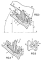
- FIG. 1 there is shown (see figure 2 ) a disk 7 carrying vanes 13 forming part of the drum of such a rotor.
- This drum is constituted by several disks 7 of this type and each disk carries at its periphery a plurality of vanes 13 (see FIG. figure 3 ).
- the blades 13 are retained in a groove 6, extending circumferentially to the outer surface of the disk 7.
- a blade 13 comprises at its base a platform 16 and a blade root 18, said to "hammer clip", which is extends under said platform 16 over part of the width thereof.
- the blade root 18 is engaged and retained in said groove 6 of the disk 7.
- the position of the blade root 18 in the groove 6 appears dashed.
- the groove 6 is delimited in its upper part, by a first lip, or upstream lip 9, and by a second lip, or downstream lip 11.
- the upstream and downstream are defined relative to the normal direction the circulation of gases through the turbomachine.
- the platform 16 of a blade 13 comes to cover a sector of the groove 6. Once all the blades 13 are in place, the platforms 16, side by side, reconstruct an annular surface which externally delimits a portion of the conical flow of the compressor. inside which the gases circulate.
- the mounting of the blades 13 requires at least one insertion slot 30 to be made on one of the annular lips 9, 11 of the groove 6, in this case the two lips have an insertion notch 30.
- This notch 30 makes it possible to engage the dawning feet 18 one after the other in the groove 6.
- Each locking device 1 comprises a latch 5 traversed by a screw 3.
- the latch has two opposite upstream side faces 21 and downstream 21 opposite. Once the lock 5 in the groove 6, the upstream side faces 19 and downstream 21 respectively face the upstream lips 9 and downstream 11 of this groove.
- the radial span 17 extends substantially over the entire width of the side face 21, while the pin 15 extends over only a portion of this width.
- the pin 15 is intended to be housed in a notch 23 formed in the downstream lip 11 of the groove 6 and the radial bearing surface 17 is intended to abut against the downstream lip 11 when the latch 5 is in the locked position (see FIG. figure 3 ).
- the upstream side face 19 of the lock is devoid of tenon or radial bearing. This face 19 is curved and constitutes a rotating bearing surface around which the latch 5 pivots to move from its unlocked position to its locked position (or vice versa). The change of position is made during the screwing (or unscrewing) of the screw 3.
- the upstream side face 19 of the lock 5 is housed between the upper edge of the upstream lip 9 of the groove 6 and the bottom 8 of this groove.
- the wall of the housing receiving the upstream side face of the latch 5, is also curved. The shape of this wall and that of the upstream side face 19 correspond to promote the guiding of the latch 5 during its pivoting.
- the downstream lateral face 21 of the lock 5 has, in regions where there is neither the tenon nor the radial bearing surface 17, a curvature such that the clearance J between the face 21 and the downstream lip 11 of the groove remains substantially constant during the rotation of the latch.
- An example of face 21 of this type is shown on the Figures 3 and 4 .
- the face 21 is in a circular arc C of appropriate diameter, centered at the point O which belongs to the rotating bearing surface formed by the side face 19. Note that a point on the face 21 substantially describes a portion of the arc C when the latch 5 pivots.
- downstream side face 21 is substantially flat. This simplifies the machining of the lock, but the assembly clearance between the lock 5 and the disc 7 varies during the rotation of the lock (so be careful that this game is not too high).
- the locking device according to the invention is interesting when the lips 9 and 11 of the groove 6 are offset, that is to say located at different distances, D and d, of the axis of A rotation of the disc (see figure 3 ).
- the average plane P passing through the lower faces of the lips 9, 11 against which the upper part of the upstream lateral face 19 and the radial bearing 17 abut respectively in the locked position of the latch 5 is shown.
- 9 and 11 are offset, the plane P is inclined at an angle with respect to the axis A of rotation of the disc, which also corresponds to the axis of the turbomachine.
- the angle a is greater than or equal to 25 °, it is preferable to use a locking device according to the invention because the use of known devices, in which the lock is mounted in translation along the axis of the screw, gives very poor results in terms of locking.
Landscapes
- Engineering & Computer Science (AREA)
- Mechanical Engineering (AREA)
- General Engineering & Computer Science (AREA)
- Structures Of Non-Positive Displacement Pumps (AREA)
Claims (10)
- Turbomaschinenscheibe, die mit einer Blockiervorrichtung ausgestattet ist, wobei die Scheibe eine Umfangsnut (6) aufweist, in der Schaufeln (13) über ihren Fuß (18) festgehalten werden können, wobei diese Nut in ihrem oberen Teil durch zwei Lippen (9, 11), eine stromaufwärtige und eine stromabwärtige, begrenzt ist und wobei die Blockiervorrichtung dazu ausgelegt ist, in die Nut (6) eingeführt zu werden, und einen Riegel (5) umfasst, der unter der Wirkung von Schubmitteln (3), welche an dem Boden der Nut (6) in Anlage sind, von einer entriegelten Position in eine verriegelte Position, in der der Riegel (5) an den Lippen (9, 11) in Anschlag ist, übergeht, wobei dieser Riegel (5) zwei gegenüberliegende Seitenflächen, eine stromaufwärtige und eine stromabwärtige (19, 21) aufweist und in der verriegelten Position ermöglicht, die Schaufeln (13) in der Umfangsrichtung der Scheibe zu blockieren, dadurch gekennzeichnet, dass eine erste der Seitenflächen (19) des Riegels (5) eine Drehanlagefläche aufweist, die gekrümmt und geeignet ist, sich zwischen dem oberen Rand einer ersten der Lippen (9) und dem Boden (8) der Nut (6) einzufügen, dass die Scheibe (7) zwischen dem oberen Rand der ersten Lippe (9) und dem Boden (8) der Nut (6) eine Aufnahme aufweist, um die Drehanlagefläche aufzunehmen, wobei die Wand dieser Aufnahme eine gekrümmte Form aufweist, die zu derjenigen der Anlagefläche im Wesentlichen ergänzend ist, und dass der Riegel (5) dazu ausgelegt ist, sich unter der Wirkung von Schubmitteln (3) um die Anlagefläche, in einer zu der Umfangsrichtung senkrechten Ebene, von seiner entriegelten Position bis in seine verriegelte Position zu drehen.
- Turbomaschinenscheibe, die mit einer Blockiervorrichtung ausgestattet ist, nach Anspruch 1, wobei die gesamte erste Seitenfläche (19) des Riegels gekrümmt ist und die Drehanlagefläche bildet.
- Turbomaschinenscheibe, die mit einer Blockiervorrichtung ausgestattet ist, nach Anspruch 1 oder 2, wobei die Schubmittel eine Schraube (3) umfassen, die mit einem den Riegel (5) durchquerenden Gewindeloch zusammenwirkt.
- Turbomaschinenscheibe, die mit einer Blockiervorrichtung ausgestattet ist, nach einem der Ansprüche 1 bis 3, wobei ein Zapfen (15) an der zweiten Seitenfläche (21) des Riegels vorspringt, wobei dieser Zapfen ermöglicht, die Umfangsbewegung des Riegels zu verhindern, wenn dieser sich in seiner verriegelten Position befindet.
- Turbomaschinenscheibe, die mit einer Blockiervorrichtung ausgestattet ist, nach einem der Ansprüche 1 bis 4, wobei eine radiale Auflagefläche (17) an der zweiten Seitenfläche (21) des Riegels, unter dem Zapfen (15) vorspringt, wobei diese Auflagefläche ermöglicht, die Radialbewegung des Riegels (5) zu verhindern, wenn dieser sich in seiner verriegelten Position befindet.
- Turbomaschinenscheibe, die mit einer Blockiervorrichtung ausgestattet ist, nach einem der Ansprüche 1 bis 5, wobei die zweite Seitenfläche (21) des Riegels gekrümmt ist.
- Turbomaschinenscheibe, die mit einer Blockiervorrichtung ausgestattet ist, nach einem der Ansprüche 1 bis 6, wobei die erste und die zweite Lippe (9, 11) der Nut in unterschiedlichen Abständen von der Rotationsachse (A) der Scheibe gelegen sind.
- Rotortrommel einer Turbomaschine, umfassend eine Turbomaschinenscheibe, die mit einer Blockiervorrichtung ausgestattet ist, nach einem der Ansprüche 1 bis 7.
- Turbomaschine, umfassend eine Turbomaschinenscheibe, die mit einer Blockiervorrichtung ausgestattet ist, nach einem der Ansprüche 1 bis 7.
- Verfahren zur Verriegelung einer Blockiervorrichtung einer Turbomaschinenscheibe, wobei eine Turbomaschinenscheibe (7), die mit einer Blockiervorrichtung ausgestattet ist, nach einem der Ansprüche 1 bis 7 bereitgestellt wird, die Anlagefläche in der Aufnahme festgesetzt wird und die Schubmittel (3) aktiviert werden, um den Riegel (5) sich um die Anlagefläche, in einer zu der Umfangsrichtung senkrechten Ebene, von seiner entriegelten Position bis in seine verriegelte Position drehen zu lassen.
Priority Applications (1)
| Application Number | Priority Date | Filing Date | Title |
|---|---|---|---|
| EP05292779.5A EP1801355B1 (de) | 2005-12-23 | 2005-12-23 | Laufschaufelschloss für eine Turbomaschinenrotorscheibe |
Applications Claiming Priority (1)
| Application Number | Priority Date | Filing Date | Title |
|---|---|---|---|
| EP05292779.5A EP1801355B1 (de) | 2005-12-23 | 2005-12-23 | Laufschaufelschloss für eine Turbomaschinenrotorscheibe |
Publications (2)
| Publication Number | Publication Date |
|---|---|
| EP1801355A1 EP1801355A1 (de) | 2007-06-27 |
| EP1801355B1 true EP1801355B1 (de) | 2015-02-11 |
Family
ID=36320187
Family Applications (1)
| Application Number | Title | Priority Date | Filing Date |
|---|---|---|---|
| EP05292779.5A Expired - Lifetime EP1801355B1 (de) | 2005-12-23 | 2005-12-23 | Laufschaufelschloss für eine Turbomaschinenrotorscheibe |
Country Status (1)
| Country | Link |
|---|---|
| EP (1) | EP1801355B1 (de) |
Families Citing this family (5)
| Publication number | Priority date | Publication date | Assignee | Title |
|---|---|---|---|---|
| US8414268B2 (en) * | 2009-11-19 | 2013-04-09 | United Technologies Corporation | Rotor with one-sided load and lock slots |
| FR2971542B1 (fr) * | 2011-02-16 | 2015-12-25 | Snecma | Dispositif de blocage circonferentiel d'aubes pour turbomachine, a deploiement radial par mouvement de rotation d'un organe du dispositif |
| US10107114B2 (en) | 2011-12-07 | 2018-10-23 | United Technologies Corporation | Rotor with relief features and one-sided load slots |
| EP2719866B1 (de) | 2012-10-12 | 2018-12-05 | Safran Aero Boosters SA | Rotorscheibe einer Turbomaschine mit einem Verschlussstück für Laufradschaufeln |
| DE102013223583A1 (de) | 2013-11-19 | 2015-05-21 | MTU Aero Engines AG | Schaufel-Scheiben-Verbund, Verfahren und Strömungsmaschine |
Citations (4)
| Publication number | Priority date | Publication date | Assignee | Title |
|---|---|---|---|---|
| US4451203A (en) * | 1981-04-29 | 1984-05-29 | Rolls Royce Limited | Turbomachine rotor blade fixings |
| US20010055527A1 (en) * | 2000-06-15 | 2001-12-27 | Yvon Goga Jean-Luc Christian | Blade locking device with hammer fastener on a disk |
| US20050008491A1 (en) * | 2003-07-07 | 2005-01-13 | Snecma Moteurs | Retention capacity of blade having an asymmetrical hammerhead connection |
| EP1726786A1 (de) * | 2005-05-26 | 2006-11-29 | Snecma | Beschaufelter Rotor |
Family Cites Families (6)
| Publication number | Priority date | Publication date | Assignee | Title |
|---|---|---|---|---|
| US3165294A (en) * | 1962-12-28 | 1965-01-12 | Gen Electric | Rotor assembly |
| US3721506A (en) * | 1971-05-25 | 1973-03-20 | Gen Electric | Split-nut blade locking assembly |
| CH581783A5 (de) * | 1975-01-30 | 1976-11-15 | Bbc Sulzer Turbomaschinen | |
| USH1258H (en) * | 1992-09-16 | 1993-12-07 | The United States Of America As Represented By The Secretary Of The Air Force | Blade lock screw |
| FR2723397B1 (fr) * | 1994-08-03 | 1996-09-13 | Snecma | Disque de compresseur de turbomachine muni d'une gorge circulaire asymetrique |
| FR2832455B1 (fr) * | 2001-11-22 | 2004-04-02 | Snecma Moteurs | Dispositif de blocage des aubes dans une rainure d'un disque |
-
2005
- 2005-12-23 EP EP05292779.5A patent/EP1801355B1/de not_active Expired - Lifetime
Patent Citations (4)
| Publication number | Priority date | Publication date | Assignee | Title |
|---|---|---|---|---|
| US4451203A (en) * | 1981-04-29 | 1984-05-29 | Rolls Royce Limited | Turbomachine rotor blade fixings |
| US20010055527A1 (en) * | 2000-06-15 | 2001-12-27 | Yvon Goga Jean-Luc Christian | Blade locking device with hammer fastener on a disk |
| US20050008491A1 (en) * | 2003-07-07 | 2005-01-13 | Snecma Moteurs | Retention capacity of blade having an asymmetrical hammerhead connection |
| EP1726786A1 (de) * | 2005-05-26 | 2006-11-29 | Snecma | Beschaufelter Rotor |
Also Published As
| Publication number | Publication date |
|---|---|
| EP1801355A1 (de) | 2007-06-27 |
Similar Documents
| Publication | Publication Date | Title |
|---|---|---|
| EP1908923B1 (de) | Vorrichtung zur Befestigung einer Leitschaufel in einem ringförmigen Gehäuse einer Strömungsmaschine, Turbinentriebwerk mit einer solchen Vorrichtung, und Verfahren zur Montage der Leitschaufel | |
| EP1584794B1 (de) | Turbomaschinenrotorscheibe mit einer Axialhalterung für die Laufschaufeln | |
| CA2640003C (fr) | Clinquant pour aube de turbomachine | |
| CA2626118C (fr) | Ensemble rotatif d'une soufflante de turbomachine | |
| CA2755653A1 (fr) | Helice non carenee a pales a calage variable pour une turbomachine | |
| EP2678531B1 (de) | Fanrotor und zugehöriges Turbostrahltriebwerk | |
| EP1873401A2 (de) | Strömungsmaschinenrotor und Strömungsmaschine, die einen solchen Rotor umfasst | |
| WO2010076493A1 (fr) | Roue de turbine avec système de rétention axiale des aubes | |
| FR2831615A1 (fr) | Redresseur fixe sectorise pour compresseur d'une turbomachine | |
| EP3433469B1 (de) | Plattform, fananordnung und fan | |
| EP1801355A1 (de) | Laufschaufelschloss für eine Turbomaschinenrotorscheibe | |
| EP1760259B1 (de) | Blockierungsvorrichtung für einen axialen Retentionsring einer Schaufel | |
| EP4072937A1 (de) | Verbesserung der radialen verriegelung eines schaufelzapfens mit einstellbarer orientierung für die nabe eines turbomaschinengebläses | |
| EP3444439B1 (de) | Turbine für eine strömungsmaschine, welche schaufeln beinhaltet, deren schaufelfüsse eine aufweitende form in axialer richtung aufweisen | |
| EP3797224B1 (de) | Verbesserte fanscheibe für eine turbomaschine | |
| FR2971542A1 (fr) | Dispositif de blocage circonferentiel d'aubes pour turbomachine, a deploiement radial par mouvement de rotation d'un organe du dispositif | |
| FR3042825B1 (fr) | Aube et disque de soufflante | |
| FR3084398A1 (fr) | Aube de turbine | |
| FR3081916A1 (fr) | Roue mobile pour turbomachine d'aeronef, comprenant un anneau de retention axiale fixe au disque par au moins un systeme de verrouillage | |
| FR3049645A1 (fr) | Ensemble rotatif pour turbomachine a jonc aval en u | |
| FR3136258A1 (fr) | Ensemble comportant un anneau forme de portions sectorisees pour aubes a calage variable, turbomachine equipee d’un tel ensemble et procede de demontage d’un tel ensemble | |
| WO2025242985A1 (fr) | Dispositif de fixation de modules de turbomachine | |
| FR3154441A1 (fr) | Dispositif de calage conique pour aube mobile et ensemble le comprenant | |
| EP4569234A1 (de) | Anordnung mit einem ring und einer schwenkbaren stützhülse für schaufelfüsse mit variabler neigung, turbinenmotor mit solch einer anordnung und verfahren zur demontage solch einer anordnung | |
| FR3108097A1 (fr) | Dispositif de positionnement pour un capot de nacelle d’un ensemble propulsif d’aeronef |
Legal Events
| Date | Code | Title | Description |
|---|---|---|---|
| PUAI | Public reference made under article 153(3) epc to a published international application that has entered the european phase |
Free format text: ORIGINAL CODE: 0009012 |
|
| AK | Designated contracting states |
Kind code of ref document: A1 Designated state(s): AT BE BG CH CY CZ DE DK EE ES FI FR GB GR HU IE IS IT LI LT LU LV MC NL PL PT RO SE SI SK TR |
|
| AX | Request for extension of the european patent |
Extension state: AL BA HR MK YU |
|
| 17P | Request for examination filed |
Effective date: 20071123 |
|
| AKX | Designation fees paid |
Designated state(s): AT BE BG CH CY CZ DE DK EE ES FI FR GB GR HU IE IS IT LI LT LU LV MC NL PL PT RO SE SI SK TR |
|
| 17Q | First examination report despatched |
Effective date: 20120705 |
|
| REG | Reference to a national code |
Ref country code: DE Ref legal event code: R079 Ref document number: 602005045806 Country of ref document: DE Free format text: PREVIOUS MAIN CLASS: F01D0005300000 Ipc: F04D0029340000 |
|
| RIC1 | Information provided on ipc code assigned before grant |
Ipc: F04D 29/34 20060101AFI20140530BHEP Ipc: F01D 5/30 20060101ALI20140530BHEP |
|
| GRAP | Despatch of communication of intention to grant a patent |
Free format text: ORIGINAL CODE: EPIDOSNIGR1 |
|
| INTG | Intention to grant announced |
Effective date: 20141002 |
|
| GRAS | Grant fee paid |
Free format text: ORIGINAL CODE: EPIDOSNIGR3 |
|
| GRAA | (expected) grant |
Free format text: ORIGINAL CODE: 0009210 |
|
| AK | Designated contracting states |
Kind code of ref document: B1 Designated state(s): AT BE BG CH CY CZ DE DK EE ES FI FR GB GR HU IE IS IT LI LT LU LV MC NL PL PT RO SE SI SK TR |
|
| REG | Reference to a national code |
Ref country code: GB Ref legal event code: FG4D Free format text: NOT ENGLISH |
|
| REG | Reference to a national code |
Ref country code: CH Ref legal event code: EP |
|
| REG | Reference to a national code |
Ref country code: IE Ref legal event code: FG4D Free format text: LANGUAGE OF EP DOCUMENT: FRENCH |
|
| REG | Reference to a national code |
Ref country code: AT Ref legal event code: REF Ref document number: 710027 Country of ref document: AT Kind code of ref document: T Effective date: 20150315 |
|
| REG | Reference to a national code |
Ref country code: DE Ref legal event code: R096 Ref document number: 602005045806 Country of ref document: DE Effective date: 20150326 |
|
| REG | Reference to a national code |
Ref country code: NL Ref legal event code: VDEP Effective date: 20150211 |
|
| REG | Reference to a national code |
Ref country code: AT Ref legal event code: MK05 Ref document number: 710027 Country of ref document: AT Kind code of ref document: T Effective date: 20150211 |
|
| REG | Reference to a national code |
Ref country code: LT Ref legal event code: MG4D |
|
| PG25 | Lapsed in a contracting state [announced via postgrant information from national office to epo] |
Ref country code: LT Free format text: LAPSE BECAUSE OF FAILURE TO SUBMIT A TRANSLATION OF THE DESCRIPTION OR TO PAY THE FEE WITHIN THE PRESCRIBED TIME-LIMIT Effective date: 20150211 Ref country code: ES Free format text: LAPSE BECAUSE OF FAILURE TO SUBMIT A TRANSLATION OF THE DESCRIPTION OR TO PAY THE FEE WITHIN THE PRESCRIBED TIME-LIMIT Effective date: 20150211 Ref country code: FI Free format text: LAPSE BECAUSE OF FAILURE TO SUBMIT A TRANSLATION OF THE DESCRIPTION OR TO PAY THE FEE WITHIN THE PRESCRIBED TIME-LIMIT Effective date: 20150211 Ref country code: SE Free format text: LAPSE BECAUSE OF FAILURE TO SUBMIT A TRANSLATION OF THE DESCRIPTION OR TO PAY THE FEE WITHIN THE PRESCRIBED TIME-LIMIT Effective date: 20150211 |
|
| PG25 | Lapsed in a contracting state [announced via postgrant information from national office to epo] |
Ref country code: AT Free format text: LAPSE BECAUSE OF FAILURE TO SUBMIT A TRANSLATION OF THE DESCRIPTION OR TO PAY THE FEE WITHIN THE PRESCRIBED TIME-LIMIT Effective date: 20150211 Ref country code: NL Free format text: LAPSE BECAUSE OF FAILURE TO SUBMIT A TRANSLATION OF THE DESCRIPTION OR TO PAY THE FEE WITHIN THE PRESCRIBED TIME-LIMIT Effective date: 20150211 Ref country code: GR Free format text: LAPSE BECAUSE OF FAILURE TO SUBMIT A TRANSLATION OF THE DESCRIPTION OR TO PAY THE FEE WITHIN THE PRESCRIBED TIME-LIMIT Effective date: 20150512 Ref country code: LV Free format text: LAPSE BECAUSE OF FAILURE TO SUBMIT A TRANSLATION OF THE DESCRIPTION OR TO PAY THE FEE WITHIN THE PRESCRIBED TIME-LIMIT Effective date: 20150211 Ref country code: IS Free format text: LAPSE BECAUSE OF FAILURE TO SUBMIT A TRANSLATION OF THE DESCRIPTION OR TO PAY THE FEE WITHIN THE PRESCRIBED TIME-LIMIT Effective date: 20150611 |
|
| PG25 | Lapsed in a contracting state [announced via postgrant information from national office to epo] |
Ref country code: RO Free format text: LAPSE BECAUSE OF FAILURE TO SUBMIT A TRANSLATION OF THE DESCRIPTION OR TO PAY THE FEE WITHIN THE PRESCRIBED TIME-LIMIT Effective date: 20150211 Ref country code: DK Free format text: LAPSE BECAUSE OF FAILURE TO SUBMIT A TRANSLATION OF THE DESCRIPTION OR TO PAY THE FEE WITHIN THE PRESCRIBED TIME-LIMIT Effective date: 20150211 Ref country code: CZ Free format text: LAPSE BECAUSE OF FAILURE TO SUBMIT A TRANSLATION OF THE DESCRIPTION OR TO PAY THE FEE WITHIN THE PRESCRIBED TIME-LIMIT Effective date: 20150211 Ref country code: EE Free format text: LAPSE BECAUSE OF FAILURE TO SUBMIT A TRANSLATION OF THE DESCRIPTION OR TO PAY THE FEE WITHIN THE PRESCRIBED TIME-LIMIT Effective date: 20150211 Ref country code: SK Free format text: LAPSE BECAUSE OF FAILURE TO SUBMIT A TRANSLATION OF THE DESCRIPTION OR TO PAY THE FEE WITHIN THE PRESCRIBED TIME-LIMIT Effective date: 20150211 |
|
| REG | Reference to a national code |
Ref country code: DE Ref legal event code: R097 Ref document number: 602005045806 Country of ref document: DE |
|
| PG25 | Lapsed in a contracting state [announced via postgrant information from national office to epo] |
Ref country code: PL Free format text: LAPSE BECAUSE OF FAILURE TO SUBMIT A TRANSLATION OF THE DESCRIPTION OR TO PAY THE FEE WITHIN THE PRESCRIBED TIME-LIMIT Effective date: 20150211 |
|
| REG | Reference to a national code |
Ref country code: FR Ref legal event code: PLFP Year of fee payment: 11 |
|
| PLBE | No opposition filed within time limit |
Free format text: ORIGINAL CODE: 0009261 |
|
| STAA | Information on the status of an ep patent application or granted ep patent |
Free format text: STATUS: NO OPPOSITION FILED WITHIN TIME LIMIT |
|
| PG25 | Lapsed in a contracting state [announced via postgrant information from national office to epo] |
Ref country code: IT Free format text: LAPSE BECAUSE OF FAILURE TO SUBMIT A TRANSLATION OF THE DESCRIPTION OR TO PAY THE FEE WITHIN THE PRESCRIBED TIME-LIMIT Effective date: 20150211 |
|
| 26N | No opposition filed |
Effective date: 20151112 |
|
| PG25 | Lapsed in a contracting state [announced via postgrant information from national office to epo] |
Ref country code: SI Free format text: LAPSE BECAUSE OF FAILURE TO SUBMIT A TRANSLATION OF THE DESCRIPTION OR TO PAY THE FEE WITHIN THE PRESCRIBED TIME-LIMIT Effective date: 20150211 |
|
| REG | Reference to a national code |
Ref country code: DE Ref legal event code: R119 Ref document number: 602005045806 Country of ref document: DE |
|
| PG25 | Lapsed in a contracting state [announced via postgrant information from national office to epo] |
Ref country code: MC Free format text: LAPSE BECAUSE OF FAILURE TO SUBMIT A TRANSLATION OF THE DESCRIPTION OR TO PAY THE FEE WITHIN THE PRESCRIBED TIME-LIMIT Effective date: 20150211 Ref country code: LU Free format text: LAPSE BECAUSE OF FAILURE TO SUBMIT A TRANSLATION OF THE DESCRIPTION OR TO PAY THE FEE WITHIN THE PRESCRIBED TIME-LIMIT Effective date: 20151223 |
|
| REG | Reference to a national code |
Ref country code: CH Ref legal event code: PL |
|
| GBPC | Gb: european patent ceased through non-payment of renewal fee |
Effective date: 20151223 |
|
| REG | Reference to a national code |
Ref country code: IE Ref legal event code: MM4A |
|
| PG25 | Lapsed in a contracting state [announced via postgrant information from national office to epo] |
Ref country code: GB Free format text: LAPSE BECAUSE OF NON-PAYMENT OF DUE FEES Effective date: 20151223 Ref country code: CH Free format text: LAPSE BECAUSE OF NON-PAYMENT OF DUE FEES Effective date: 20151231 Ref country code: LI Free format text: LAPSE BECAUSE OF NON-PAYMENT OF DUE FEES Effective date: 20151231 Ref country code: IE Free format text: LAPSE BECAUSE OF NON-PAYMENT OF DUE FEES Effective date: 20151223 Ref country code: DE Free format text: LAPSE BECAUSE OF NON-PAYMENT OF DUE FEES Effective date: 20160701 |
|
| REG | Reference to a national code |
Ref country code: FR Ref legal event code: PLFP Year of fee payment: 12 |
|
| PG25 | Lapsed in a contracting state [announced via postgrant information from national office to epo] |
Ref country code: BG Free format text: LAPSE BECAUSE OF FAILURE TO SUBMIT A TRANSLATION OF THE DESCRIPTION OR TO PAY THE FEE WITHIN THE PRESCRIBED TIME-LIMIT Effective date: 20150211 Ref country code: HU Free format text: LAPSE BECAUSE OF FAILURE TO SUBMIT A TRANSLATION OF THE DESCRIPTION OR TO PAY THE FEE WITHIN THE PRESCRIBED TIME-LIMIT; INVALID AB INITIO Effective date: 20051223 |
|
| PG25 | Lapsed in a contracting state [announced via postgrant information from national office to epo] |
Ref country code: CY Free format text: LAPSE BECAUSE OF FAILURE TO SUBMIT A TRANSLATION OF THE DESCRIPTION OR TO PAY THE FEE WITHIN THE PRESCRIBED TIME-LIMIT Effective date: 20150211 |
|
| PG25 | Lapsed in a contracting state [announced via postgrant information from national office to epo] |
Ref country code: TR Free format text: LAPSE BECAUSE OF FAILURE TO SUBMIT A TRANSLATION OF THE DESCRIPTION OR TO PAY THE FEE WITHIN THE PRESCRIBED TIME-LIMIT Effective date: 20150211 |
|
| REG | Reference to a national code |
Ref country code: FR Ref legal event code: PLFP Year of fee payment: 13 |
|
| PG25 | Lapsed in a contracting state [announced via postgrant information from national office to epo] |
Ref country code: PT Free format text: LAPSE BECAUSE OF FAILURE TO SUBMIT A TRANSLATION OF THE DESCRIPTION OR TO PAY THE FEE WITHIN THE PRESCRIBED TIME-LIMIT Effective date: 20150211 |
|
| PGFP | Annual fee paid to national office [announced via postgrant information from national office to epo] |
Ref country code: FR Payment date: 20191120 Year of fee payment: 15 |
|
| PG25 | Lapsed in a contracting state [announced via postgrant information from national office to epo] |
Ref country code: FR Free format text: LAPSE BECAUSE OF NON-PAYMENT OF DUE FEES Effective date: 20201231 |
|
| PGFP | Annual fee paid to national office [announced via postgrant information from national office to epo] |
Ref country code: BE Payment date: 20241121 Year of fee payment: 20 |
|
| REG | Reference to a national code |
Ref country code: BE Ref legal event code: MK Effective date: 20251223 |