EP1801383B1 - Moteur à combustion interne doté d'un chargement de registre - Google Patents
Moteur à combustion interne doté d'un chargement de registre Download PDFInfo
- Publication number
- EP1801383B1 EP1801383B1 EP06024094.2A EP06024094A EP1801383B1 EP 1801383 B1 EP1801383 B1 EP 1801383B1 EP 06024094 A EP06024094 A EP 06024094A EP 1801383 B1 EP1801383 B1 EP 1801383B1
- Authority
- EP
- European Patent Office
- Prior art keywords
- exhaust
- gas turbocharger
- compressor
- line
- internal combustion
- Prior art date
- Legal status (The legal status is an assumption and is not a legal conclusion. Google has not performed a legal analysis and makes no representation as to the accuracy of the status listed.)
- Not-in-force
Links
Images

Classifications
-
- F—MECHANICAL ENGINEERING; LIGHTING; HEATING; WEAPONS; BLASTING
- F02—COMBUSTION ENGINES; HOT-GAS OR COMBUSTION-PRODUCT ENGINE PLANTS
- F02B—INTERNAL-COMBUSTION PISTON ENGINES; COMBUSTION ENGINES IN GENERAL
- F02B37/00—Engines characterised by provision of pumps driven at least for part of the time by exhaust
- F02B37/007—Engines characterised by provision of pumps driven at least for part of the time by exhaust with exhaust-driven pumps arranged in parallel, e.g. at least one pump supplying alternatively
-
- F—MECHANICAL ENGINEERING; LIGHTING; HEATING; WEAPONS; BLASTING
- F01—MACHINES OR ENGINES IN GENERAL; ENGINE PLANTS IN GENERAL; STEAM ENGINES
- F01N—GAS-FLOW SILENCERS OR EXHAUST APPARATUS FOR MACHINES OR ENGINES IN GENERAL; GAS-FLOW SILENCERS OR EXHAUST APPARATUS FOR INTERNAL-COMBUSTION ENGINES
- F01N13/00—Exhaust or silencing apparatus characterised by constructional features
- F01N13/011—Exhaust or silencing apparatus characterised by constructional features having two or more purifying devices arranged in parallel
-
- F—MECHANICAL ENGINEERING; LIGHTING; HEATING; WEAPONS; BLASTING
- F02—COMBUSTION ENGINES; HOT-GAS OR COMBUSTION-PRODUCT ENGINE PLANTS
- F02B—INTERNAL-COMBUSTION PISTON ENGINES; COMBUSTION ENGINES IN GENERAL
- F02B37/00—Engines characterised by provision of pumps driven at least for part of the time by exhaust
- F02B37/004—Engines characterised by provision of pumps driven at least for part of the time by exhaust with exhaust drives arranged in series
-
- F—MECHANICAL ENGINEERING; LIGHTING; HEATING; WEAPONS; BLASTING
- F02—COMBUSTION ENGINES; HOT-GAS OR COMBUSTION-PRODUCT ENGINE PLANTS
- F02B—INTERNAL-COMBUSTION PISTON ENGINES; COMBUSTION ENGINES IN GENERAL
- F02B37/00—Engines characterised by provision of pumps driven at least for part of the time by exhaust
- F02B37/013—Engines characterised by provision of pumps driven at least for part of the time by exhaust with exhaust-driven pumps arranged in series
-
- F—MECHANICAL ENGINEERING; LIGHTING; HEATING; WEAPONS; BLASTING
- F02—COMBUSTION ENGINES; HOT-GAS OR COMBUSTION-PRODUCT ENGINE PLANTS
- F02B—INTERNAL-COMBUSTION PISTON ENGINES; COMBUSTION ENGINES IN GENERAL
- F02B37/00—Engines characterised by provision of pumps driven at least for part of the time by exhaust
- F02B37/12—Control of the pumps
-
- F—MECHANICAL ENGINEERING; LIGHTING; HEATING; WEAPONS; BLASTING
- F02—COMBUSTION ENGINES; HOT-GAS OR COMBUSTION-PRODUCT ENGINE PLANTS
- F02B—INTERNAL-COMBUSTION PISTON ENGINES; COMBUSTION ENGINES IN GENERAL
- F02B37/00—Engines characterised by provision of pumps driven at least for part of the time by exhaust
- F02B37/12—Control of the pumps
- F02B37/16—Control of the pumps by bypassing charging air
-
- F—MECHANICAL ENGINEERING; LIGHTING; HEATING; WEAPONS; BLASTING
- F02—COMBUSTION ENGINES; HOT-GAS OR COMBUSTION-PRODUCT ENGINE PLANTS
- F02B—INTERNAL-COMBUSTION PISTON ENGINES; COMBUSTION ENGINES IN GENERAL
- F02B37/00—Engines characterised by provision of pumps driven at least for part of the time by exhaust
- F02B37/12—Control of the pumps
- F02B37/18—Control of the pumps by bypassing exhaust from the inlet to the outlet of turbine or to the atmosphere
- F02B37/183—Arrangements of bypass valves or actuators therefor
-
- F—MECHANICAL ENGINEERING; LIGHTING; HEATING; WEAPONS; BLASTING
- F01—MACHINES OR ENGINES IN GENERAL; ENGINE PLANTS IN GENERAL; STEAM ENGINES
- F01N—GAS-FLOW SILENCERS OR EXHAUST APPARATUS FOR MACHINES OR ENGINES IN GENERAL; GAS-FLOW SILENCERS OR EXHAUST APPARATUS FOR INTERNAL-COMBUSTION ENGINES
- F01N13/00—Exhaust or silencing apparatus characterised by constructional features
- F01N13/08—Other arrangements or adaptations of exhaust conduits
- F01N13/10—Other arrangements or adaptations of exhaust conduits of exhaust manifolds
- F01N13/107—More than one exhaust manifold or exhaust collector
-
- Y—GENERAL TAGGING OF NEW TECHNOLOGICAL DEVELOPMENTS; GENERAL TAGGING OF CROSS-SECTIONAL TECHNOLOGIES SPANNING OVER SEVERAL SECTIONS OF THE IPC; TECHNICAL SUBJECTS COVERED BY FORMER USPC CROSS-REFERENCE ART COLLECTIONS [XRACs] AND DIGESTS
- Y02—TECHNOLOGIES OR APPLICATIONS FOR MITIGATION OR ADAPTATION AGAINST CLIMATE CHANGE
- Y02T—CLIMATE CHANGE MITIGATION TECHNOLOGIES RELATED TO TRANSPORTATION
- Y02T10/00—Road transport of goods or passengers
- Y02T10/10—Internal combustion engine [ICE] based vehicles
- Y02T10/12—Improving ICE efficiencies
Definitions
- the invention relates to an internal combustion engine, in particular for a motor vehicle, having at least one first exhaust gas turbocharger, which has at least one first turbine and at least one first compressor, at least one second exhaust gas turbocharger, which has at least one second turbine and at least one second compressor, according to the preamble of
- the invention further relates to a method for operating an internal combustion engine, in particular for a motor vehicle, wherein a turbine of a first exhaust gas turbocharger is permanently exposed to exhaust gas during operation of the internal combustion engine and a turbine of a second exhaust gas turbocharger optionally in response to an operating condition of the internal combustion engine with Exhaust gas is applied, according to the preamble of claim 11.
- At least two exhaust gas turbochargers are provided, which are acted upon by at least one additional switching element on the exhaust and fresh air side operating point depending on exhaust gas or air.
- register concepts are suitable, which apply an ATL alone at low engine speeds and switch on a second ATL for the nominal power range, without forgoing the compaction work of the first ATL, ie the first ATL continues to contribute a very large part entire loading work at.
- the first ATL continues to contribute a very large part entire loading work at.
- the ATL In a conventional monoturbine concept, the ATL must be able to cover the rated horsepower of the engine alone, so it must be sized accordingly. This inevitably allows only a correspondingly sluggish response at low exhaust gas mass flows, as they are present at low engine speeds. In a classic twin or biturbane concept, the available exhaust gas energy must be divided into two ATLs even with small exhaust gas mass flows, ie low engine speeds.
- ATL ATL design
- ATL ATL
- the admission of the ATLs with exhaust gas takes place in the register concept such that, with small exhaust gas mass flows (small engine speeds), only one of the two ATLs is supplied with the entire available exhaust gas via a switchable pipe guide in the exhaust manifold.
- the second ATL is switched on and the register system is operated up to the rated power analogous to a conventional twin turbosystem.
- the two ATLs share the required mass flow at the nominal point with approximately 40% to 60% or approximately 45% to 55% in favor of the larger ATL.
- a necessary for this system exhaust-side interconnection of the turbines is for example from the DE 198 37 978 A1 known.
- the one-ATL operation in a register system of the type described above can by no means serve the air mass flow requirements of the engine in the middle and high speed range, which is why a connection of the second ATL is necessary.
- the connection of a second ATL is more difficult to control. Switching brings, as already described above, the disadvantage that this ATL must be very large, so that he can supply the air mass requirement in the rated power point of the engine alone. This leads to corresponding package disadvantages.
- the availability of ATL is limited for Otto engine applications, in particular with nominal powers above 200kW and exhaust gas temperatures> 950 ° C. against this background, the inclusion of a second ATL for a Otto register concept is more effective.
- From the DE 43 10 148 C2 is an internal combustion engine with register charging known, with a first exhaust gas turbocharger constantly provides charge air and a second exhaust gas turbocharger is optionally switched on.
- a pressure output of a compressor of the second exhaust gas turbocharger is connected to the inlet of a turbine of this second exhaust gas turbocharger.
- the second exhaust gas turbocharger is constantly maintained at a speed which he needs for charge air supply of the internal combustion engine, so that when connecting the second Exhaust gas turbocharger by disconnecting the pressure output of the compressor of the second exhaust gas turbocharger from the inlet of the turbine of this second exhaust gas turbocharger and connecting the pressure output of the compressor of the second exhaust gas turbocharger with the leading to the engine combustion air supply line without pressure jump immediately the required charge air pressure is present.
- a pressure output of a second compressor of a second exhaust gas turbocharger is connected via a first line to a pressure outlet of a first compressor and via a second line to the suction inlet of the first compressor.
- a first valve device is provided in the first line and a second valve device in the second line. The control of the two said valves is carried out in the manner described below.
- the first valve device is closed, so that the entire exhaust gas is passed to the turbine of the first exhaust gas turbocharger.
- the second exhaust gas turbocharger is not exposed to exhaust gas.
- the charge pressure applied by the compressor keeps a check valve closed, so that the charge air can not escape via the compressor of the second turbocharger.
- the first valve device is slightly opened, so that a part of the exhaust gases reaches the turbine of the second exhaust gas turbocharger and the compressor driven by this turbine promotes against the aforementioned check valve.
- a vent valve is placed in a bypass line to prevent the compressor from exceeding its surge limit. The vent valve is switched by the pressure difference in front of and behind the check valve. If the pressure falls below a certain pressure difference, the venting valve closes, so that switching to an operation with two turbochargers is effected by an abrupt increase in pressure upstream of the non-return valve.
- the invention has for its object to improve an internal combustion engine and a method for operating this with respect to the operating behavior when connecting another exhaust gas turbocharger.
- a pressure outlet of the second compressor of the second exhaust gas turbocharger is connected via at least one first line to a pressure outlet of the first compressor of the first exhaust gas turbocharger and via at least one second line to a suction inlet of the first exhaust gas turbocharger, wherein in the first conduit at least a first valve device and in the second line at least one second valve device is arranged, wherein the first valve device is designed such that it closes the first line when a charge air pressure at the pressure output of the second compressor of the second exhaust gas turbocharger is smaller than a charge air pressure at the pressure outlet of the first Compressor of the first exhaust gas turbocharger and the first line opens when a charge air pressure at the pressure outlet of the second compressor of the second exhaust gas turbocharger is equal to or greater than a charge air pressure at the pressure outlet of the first compressor of the first Ab gasturboladers and wherein the second valve device is designed such that it opens the second line when a charge air pressure at the pressure outlet of
- the second exhaust gas turbocharger can be switched on without noticeable charge pressure drop or without torque fluctuations when an air mass flow requirement of the internal combustion engine can no longer be served by the first exhaust gas turbocharger alone, since the pressure output of the second exhaust gas turbocharger to be connected only then via the first line is connected to the combustion air supply of the internal combustion engine, when the second exhaust gas turbocharger has reached at least the same charge air pressure, as it is already generated by the first exhaust gas turbocharger.
- the exhaust gas turbochargers are connected in series.
- the second valve device comprises a throttle element with cover flap, wherein the cover flap is arranged and configured such that it selectively opens or closes an opening of the throttle element, and the second valve means a throttle element with cover, wherein the cover flap is arranged and formed in that it selectively opens or closes an opening of the throttle element, the first valve device and the second valve device being coupled to one another, in particular mechanically, such that the second valve device closes the second line when the first valve device opens the first line and the second valve device the second conduit opens when the first valve means closes the first conduit.
- the mechanical coupling of the first and second valve means comprises a shaft pivotally mounted about a fixed pivot joint, at the ends of each of which the first and second valve means is arranged.
- the coupling element is connected to an actuating element which is designed and arranged such that this actuating element either secures only the end stops of the coupling element and / or the movement of the coupling element for opening or closing Closing of the first and second valve element is supported.
- This actuator is for example an actuator, in particular a pneumatic jack, an e-actuator or a magnetic switch.
- a pressure sensor is arranged in the first line on both sides of the first valve element.
- At least one branch is arranged in an exhaust duct of the internal combustion engine upstream of the first turbine of the first exhaust gas turbocharger, which is connected to the second turbine of the second exhaust gas turbocharger, wherein at least one switching flap is arranged at the branch and is designed that this connects either the exhaust duct either only with the first turbine or both with the first turbine and via the junction with the second turbine.
- a pressure output of a compressor of the second exhaust gas turbocharger is either connected to a suction of a compressor of the first exhaust gas turbocharger when a charge air pressure at the pressure outlet of the compressor of the second exhaust gas turbocharger is smaller than a charge air pressure at a pressure outlet of the compressor of the first exhaust gas turbocharger, or is connected to the pressure outlet of the compressor of the first exhaust gas turbocharger;
- a charge air pressure at the pressure outlet of the compressor of the second exhaust gas turbocharger is equal to or greater than a charge air pressure at the pressure outlet of the compressor of the first exhaust gas turbocharger.
- the second exhaust gas turbocharger can be switched on without noticeable charge pressure drop or without torque fluctuations when an air mass flow requirement of the internal combustion engine can no longer be served by the first exhaust gas turbocharger alone, since the pressure output of the second exhaust gas turbocharger to be connected only then via the first line is connected to the combustion air supply of the internal combustion engine, when the second exhaust gas turbocharger has reached at least the same charge air pressure, as it is already generated by the first exhaust gas turbocharger.
- the exhaust gas turbochargers are connected in series.
- the turbine of the second exhaust gas turbocharger is exposed to exhaust gas when an air mass flow demand of the internal combustion engine can not be operated by the first exhaust gas turbocharger alone.
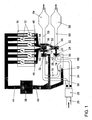
- an internal combustion engine comprises an engine block 10 with working cylinders 12, a first exhaust gas turbocharger (ATL) 14 with a first turbine 16 and a first compressor 18, a second exhaust gas turbocharger 20 with a second turbine 22 and a second compressor 24, a Verbrennungs Kunststoffansaugrohr 26, an air filter 28, a first fresh air pipe 30, which connects the air filter 28 with a suction inlet 32 of the first compressor 18 of the first exhaust gas turbocharger 14, a second fresh air pipe 34, which the air filter 28 with a suction 36 of the second compressor 24 of the second exhaust gas turbocharger 20th connects, a charge air cooler 38, a first charge air tube 40 which connects a pressure outlet 42 of the first compressor 18 of the first exhaust gas turbocharger 14 with the charge air cooler 38, a second charge air tube 44 which connects the charge air cooler 38 with the working cylinders 12, a first exhaust manifold 46 un d a second exhaust manifold 48, which permanently
- a pressure outlet 66 of the second compressor 24 of the second exhaust gas turbocharger 20 is connected via a first line 68 to the pressure outlet 42 of the first compressor 18 of the first exhaust gas turbocharger 14 or to the first charge air tube 40. Furthermore, the pressure outlet 66 of the second compressor 24 of the second exhaust gas turbocharger 20 via a second line 70 to the suction inlet 32 of the first compressor 18 of the first Exhaust gas turbocharger 14 and the first fresh air pipe 30 connected.
- a first valve means 72, 94 and in the second conduit 70, a second valve means 74, 86, 92 are arranged in the first conduit 68.
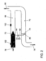
- FIG. 2 and 3 has an arrow 76 in the direction of the connection of the first line 68 to the pressure outlet 42 of the first compressor 18 of the first exhaust gas turbocharger 14 and the first charge air tube 40, an arrow 78 in the direction of the connection of the second line 70 to the suction inlet 32 of the first compressor 18 of the first exhaust gas turbocharger 14 and with the first fresh air pipe 30 and an arrow 80 in the direction of the pressure output 66 of the second compressor 24 of the second exhaust gas turbocharger 20.
- a coupling element 82 mechanically connects the first valve device 72 and the second valve device 74 with each other so that the valve devices 72 , 74 together with the coupling element 82 form a switching element.
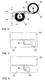
- This coupling element 82 is mounted pivotably about a pivot bearing or fixedly mounted pivot point 84. To assist the movement of the valve means 72, 74 or the pivoting movement of the coupling element 82 and / or for securing end stops, the coupling element 82 is optionally connected to an actuator and / or an end stop, as later with reference to FIGS Fig. 6 to 8 will be explained in more detail.
- the first valve device 72 is designed as a flow-favorable check valve and the second valve device 74 as a throttle element.
- a closure flap of the throttle element 74 is designated ( Fig. 2 and 3 ).
- the two exhaust gas turbochargers 14, 20 form a register network.
- the first exhaust gas turbocharger 14 is in this case an ATL in register combination, which is always in operation and performs the Aufladarbeit essentially alone at low engine speeds or dynamic load requirements.
- the first ATL 14 is supported by the second ATL 20.
- the second ATL may be made larger, equal to, or smaller than the first ATL 14, and has no part in the charge work at low engine speeds. Only from average engine speeds, this second ATL 20 is switched to the first ATL 14th
- the same compressor pressure ratio is established according to the invention before connecting the second ATL 20 in a Zuschaltvorgang to zuzugateden second ATL 20 having the in-operation first ATL 14, ie a constant intake manifold pressure in the first charge air duct 40th manufactured to achieve a constant torque output of the engine.
- the above-illustrated interconnection of the ATLs 14, 20 on the fresh air side is characterized by the switching means combined valve means 72, 94 (check valve) and 74, 86, 92 (throttle element), which are placed in the two lines 68 and 70.
- the check valve 72 separates the pressure side 42 of the first ATL 14 from the pressure side 66 of the second ATL 20 in those operating ranges in which only the first ATL 14 is in operation. If the first ATL 14 reaches its operating limits, the second ATL 20 is switched on. On the exhaust side, the second turbine 22 of the second ATL 20 is acted upon with exhaust gas, whereby the second ATL 20 builds up speed.
- the second compressor 24 of the second ATL 20 begins to build up a pressure ratio and the pressure at the compressor outlet 66 of the second ATL 20 increases.
- the check valve 72 remains closed due to the pressure difference applied there (pressure in the charge air pipe 40 is greater than pressure in the first line 68).
- the rising pressure to (downstream) the second compressor 24 of the second ATL 20 is thus relaxed via the open throttle point 74 via the second line 70, the circulated via the second compressor 24 of the second ATL 20 air is throttled back to the suction port 32 of the first Compressor 18 of the first ATL 14 supplied.
- the throttle point 74 is designed such that the slope of the throttle characteristic runs as parallel as possible to the surge limit of the second compressor 24 of the second ATL 20. Due to the course of the throttle characteristic, the operating line of the second compressor 24 of the second ATL 20 is terminated. This ensures a safe run-up of the second ATL 20 with an appropriate design of the throttle characteristic, it being ensured that, firstly, the second compressor 24 of the second ATL 20 does not exceed its surge limit and second, the second ATL 20 runs high with lowest possible volume flows, creating the lowest possible Power consumption is realized on the compressor wheel. Thus, the second compressor 24 of the second ATL 20 runs up to the pressure ratio of the first compressor 18 of the first ATL 14 under optimum conditions.
- the pivot point 84 of the coupling element 82 between the check valve 72 and the flap 86 of the throttle 74 can then be selected centrally.
- the influencing of the moment about the pivot point 84 of the switching element 72, 74, 82, 86, 92, 94 is possible on the part of the first ATL 14 only by the pressure in the first charge air tube 40. If the second turbine 22 of the second ATL 20 exhaust gas mass flow by closing the exhaust-side switching elements in the form of the exhaust valves 62 and 64 withdrawn, the second compressor 24 of the second ATL 20 can build up less pressure and the moment about the switching element 72, 74, 82, 86, 92, 94 is determined by the pressure difference in the first conduit 86 and the first charge air tube 40. This results in that the check valve 72 is closed and the closure flap 86 of the throttle 74 is open.
- the second compressor 24 of the second ATL 20 becomes the pressure in the first approximately second Increase line 68, 70 until the pressures in the two lines 68, 70 on the one hand and the first charge air tube 40 on the other hand are the same.
- the check valve 72 is now kept closed only by a very small force (resulting from the pressure difference in the second conduit 70 and the first fresh air tube 30 on the closure flap 86 of the throttle 74).
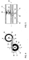
- Out 4 and 5 is a preferred embodiment of the arrangement and design of the coupling element 82 can be seen.
- the coupling element is designed as a fixed shaft 82, wherein the check valve 72 and the closure flap 86 of the throttle 74 are arranged at a respective end of the shaft 82 and. are attached to respective attachment points 90 via corresponding levers. With 92 an aperture of the throttle point 74 is designated.
- For the check valve 72 is a seat ring 94 in the first line 68 is arranged.
- the fixedly mounted shaft 82 is lifted out of the plane of the drawing at the bottom and, for the sake of better understanding, is shown before the other elements of the drawing.
- an articulation lever 96 is arranged for an actuator or an end stop.
- the two lines 68 and 70 are firmly connected to one another in the region of the switching element 72, 74, 82, 86, 92, 94.
- the shaft 82 is mounted, which penetrates on each side in each case a line 68, 70.
- a seal between line interior and shaft bearing Is to be designed so that no gases from the interior of the lines 68, 70 can escape to the outside, still from the outside gases in the interior of the lines 68, 70 can be sucked.
- a closure element 72, 74 of the switching element is attached in each case via a lever arm.
- this is the aerodynamic closure / remindechlagventil 72.
- This valve 72 closes in combination with the likewise flow-optimized seat 94, the first line 68 of the first charge air pipe 40 whenever only the first ATL 14 is in operation.
- the lowest possible pressure loss is ensured if, when the valve 72 is open, both ATLs 14, 20 are in common operation.
- the flap 86 of the throttle point 74 On the other end of the shaft in the second line 70.
- the throttle point 74 itself is formed by the annular aperture 92 in the second conduit 70.
- the flap 86 closes the restrictor 74, 92 as soon as the closure / check valve 72 opens in the first line 68, since both closure elements 72, 86 are coupled to one another via the common shaft 82. How out Fig. 4 can be seen, the shaft 82 is led out on one side of the line network. At the attached there further lever arm 96, either an active actuator or an element for Endanschlags rejoin be articulated.
- the ATL configuration of the register system allows the switching element 72, 74, 82, 86, 92, 94 to be designed with respect to the flow effective areas on check valve 72 and throttle 74 or flap 86 and the arrangements of lever arms to check valve 72 and throttle 74, respectively or flap 86 such that the moments about the pivot point 84 are dominated by the forces acting on the check valve 72, can be dispensed with an end stop as described above.
- the exhaust-side switching element in the form of the exhaust flaps 62, 64 (FIG. Fig. 1 ) is distinguished by the fact that the two exhaust manifolds 46, 48 designed as manifold halves open into one half each of the exhaust gas line leading to the first ATL 14.
- the two halves of the exhaust pipe are completely separated from each other by a central partition, which prevents the exhaust gases of one manifold half from coming into contact with those of the other manifold half.
- a crosstalk caused by the opening of the individual exhaust valves (not shown) pressure waves to each other manifold and thus engine half is prevented.
- the exhaust-side switching element thus has two flaps 62, 64, one in each half of the exhaust pipe 46, 48, which are controlled via an actuator (not shown).
- the separation of the exhaust gas flows 46, 48 is ensured even when the flaps 62, 64 open.
- the flaps 62, 64 are closed, the entire exhaust gas mass flow and thus the total exhaust gas enthalpy are directed to the first turbine 16 of the first ATL 14, which is embodied, for example, as TwinScroll ATL.
- Only with increasing opening of the exhaust valves 62, 64 is exhaust gas increasingly directed to the second turbine 22 of the second ATL 20, whereby the already described above Zuschaltvorgang of the second ATL 20 is initiated.
- the second ATL 20 is also designed, for example, as a TwinScroll ATL or as a conventional single-scroll ATL. In the case of using a single scroll ATL, the separation of the exhaust pipes 46, 48 terminates only immediately before entering the turbine housing of the second turbine 22 of the second ATL 20.
Landscapes
- Engineering & Computer Science (AREA)
- Chemical & Material Sciences (AREA)
- Combustion & Propulsion (AREA)
- Mechanical Engineering (AREA)
- General Engineering & Computer Science (AREA)
- Supercharger (AREA)
Claims (12)
- Moteur à combustion interne, en particulier pour un véhicule automobile, comprenant au moins un premier turbocompresseur à gaz d'échappement (14), qui présente au moins une première turbine (16) et au moins un premier compresseur (18), au moins un deuxième turbocompresseur à gaz d'échappement (20) qui présente au moins une deuxième turbine (22) et au moins un deuxième compresseur (24),- une sortie de pression (66) du deuxième compresseur (24) du deuxième turbocompresseur à gaz d'échappement (20) étant connectée par le biais d'au moins une première conduite (68) à une sortie de pression (42) du premier compresseur (18) du premier turbocompresseur à gaz d'échappement (14) et par le biais d'au moins une deuxième conduite (70) à une entrée d'admission (32) du premier compresseur (18) du premier turbocompresseur à gaz d'échappement (14),- au moins un premier dispositif de soupape (72, 94) étant disposé dans la première conduite (68) et au moins un deuxième dispositif de soupape (74, 86, 92) étant disposé dans la deuxième conduite (70),- le premier dispositif de soupape (72, 94) étant réalisé de telle sorte que celui-ci ferme la première conduite (68) lorsqu'une pression d'air de suralimentation à la sortie de pression (66) du deuxième compresseur (24) du deuxième turbocompresseur à gaz d'échappement (20) est inférieure à une pression d'air de suralimentation à la sortie de pression (42) du premier compresseur (18) du premier turbocompresseur à gaz d'échappement (14),- et ouvre la première conduite (68) lorsqu'une pression d'air de suralimentation à la sortie de pression (66) du deuxième compresseur (24) du deuxième turbocompresseur à gaz d'échappement (20) est supérieure ou égale à une pression d'air de suralimentation à la sortie de pression (42) du premier compresseur (18) du premier turbocompresseur à gaz d'échappement (14) et- le deuxième dispositif de soupape (74, 86, 92) étant réalisé de telle sorte que celui-ci ouvre la deuxième conduite (70) lorsqu'une pression d'air de suralimentation à la sortie de pression (66) du deuxième compresseur (24) du deuxième turbocompresseur à gaz d'échappement (20) est inférieure à une pression d'air de suralimentation à la sortie de pression (42) du premier compresseur (18) du premier turbocompresseur à gaz d'échappement (14),- et ferme la deuxième conduite (70) lorsqu'une pression d'air de suralimentation à la sortie de pression (66) du deuxième compresseur (24) du deuxième turbocompresseur à gaz d'échappement (20) est supérieure ou égale à une pression d'air de suralimentation à la sortie de pression (42) du premier compresseur (18) du premier turbocompresseur à gaz d'échappement (14),- un premier collecteur de gaz d'échappement (46) réalisé de préférence sous forme de moitié de collecteur, et un deuxième collecteur de gaz d'échappement (48) réalisé de préférence sous forme de moitié de collecteur, reliant les cylindres de travail (12) à la première turbine (16) du premier turbocompresseur à gaz d'échappement (14),- et le premier collecteur de gaz d'échappement (46) pouvant être connecté par le biais d'une première conduite de gaz d'échappement (50) et le deuxième collecteur de gaz d'échappement (48) pouvant être connecté par le biais d'une deuxième conduite de gaz d'échappement (52) à la deuxième turbine (22) du deuxième turbocompresseur à gaz d'échappement (20), caractérisé en ce- qu'un premier clapet de gaz d'échappement (62) est prévu, lequel relie le premier collecteur de gaz d'échappement (46) de manière sélective à la première conduite de gaz d'échappement (50) ou les sépare l'un de l'autre (46, 50), et un deuxième clapet de gaz d'échappement (64) est prévu, lequel relie le deuxième collecteur de gaz d'échappement (48) de manière sélective à la deuxième conduite de gaz d'échappement (52) ou les sépare l'un de l'autre (48, 52).
- Moteur à combustion interne selon la revendication 1, caractérisé en ce que le premier dispositif de soupape comprend un clapet antiretour (72, 94), qui est disposé et réalisé de telle sorte que le clapet antiretour (72, 94) bloque la première conduite (68) contre un écoulement dans la direction de la sortie de pression (66) du compresseur (24) du deuxième turbocompresseur à gaz d'échappement (20).
- Moteur à combustion interne selon la revendication 1 ou 2, caractérisé en ce que le deuxième dispositif de soupape comprend un élément d'étranglement (92) avec un clapet de recouvrement (86), le clapet de recouvrement (86) étant disposé et réalisé de telle sorte qu'il ouvre ou ferme de manière sélective une ouverture (74) de l'élément d'étranglement (92).
- Moteur à combustion interne selon au moins l'une quelconque des revendications précédentes, caractérisé en ce que le premier dispositif de soupape (72, 94) et le deuxième dispositif de soupape (74, 86, 92) sont accouplés l'un à l'autre de telle sorte que le deuxième dispositif de soupape (74, 86, 92) ferme la deuxième conduite (70) lorsque le premier dispositif de soupape (72, 94) ouvre la première conduite (68) et que le deuxième dispositif de soupape (74, 86, 92) ouvre la deuxième conduite (70) lorsque le premier dispositif de soupape (72, 94) ferme la première conduite (68).
- Moteur à combustion interne selon la revendication 4, caractérisé en ce que le premier dispositif de soupape (72, 94) et le deuxième dispositif de soupape (74, 86, 92) sont accouplés l'un à l'autre mécaniquement par le biais d'un élément d'accouplement (82).
- Moteur à combustion interne selon la revendication 5, caractérisé en ce que l'accouplement mécanique du premier dispositif de soupape (72, 94) et du deuxième dispositif de soupape (74, 86, 92) comprend un arbre (82) monté de manière pivotante autour d'une articulation pivotante (84) fixe, aux extrémités duquel est à chaque fois disposé le premier dispositif de soupape (72, 94) respectivement le deuxième dispositif de soupape (74, 86, 92).
- Moteur à combustion interne selon au moins l'une quelconque des revendications 5 ou 6, caractérisé en ce que l'élément d'accouplement (82) est connecté à un élément de commande (98, 100) qui est réalisé et disposé de telle sorte que cet élément de commande (98, 100) ne fixe que les butées de fin de course de l'élément d'accouplement (82) et/ou ne supporte que le mouvement de l'élément d'accouplement (82) pour l'ouverture ou la fermeture du premier élément de soupape (72, 94) et du deuxième élément de soupape (74, 86, 92).
- Moteur à combustion interne selon la revendication 7, caractérisé en ce que l'élément de commande est un actionneur (98, 100), en particulier une boîte de levage pneumatique, un actionneur électronique ou un commutateur magnétique.
- Moteur à combustion interne selon au moins l'une quelconque des revendications précédentes, caractérisé en ce qu'un capteur de pression (102) est à chaque fois disposé dans la première conduite (68) de chaque côté du premier élément de soupape (72, 94).
- Moteur à combustion interne selon au moins l'une quelconque des revendications précédentes, caractérisé en ce qu'au moins un clapet de commutation (62, 64) est disposé et réalisé sur la conduite de gaz d'échappement (50, 52), de telle sorte que celui-ci ne relie de manière sélective le collecteur de gaz d'échappement (46, 48) qu'à la première turbine (16) du premier turbocompresseur à gaz d'échappement (14) ou à la fois à la première turbine (16) du premier turbocompresseur à gaz d'échappement (14) et par le biais de la conduite de gaz d'échappement (50, 52) à la deuxième turbine (22) du deuxième turbocompresseur à gaz d'échappement (20).
- Procédé pour faire fonctionner un moteur à combustion interne, en particulier pour un véhicule automobile,- dans lequel, pendant le fonctionnement du moteur à combustion interne, une turbine d'un premier turbocompresseur à gaz d'échappement est sollicitée en permanence avec du gaz d'échappement, et- dans lequel une turbine d'un deuxième turbocompresseur à gaz d'échappement est sollicitée de manière sélective en fonction d'un état de fonctionnement du moteur à combustion interne avec du gaz d'échappement,- dans lequel une sortie de pression d'un compresseur du deuxième turbocompresseur à gaz d'échappement est connectée soit à une entrée d'admission d'un compresseur du premier turbocompresseur à gaz d'échappement, lorsqu'une pression d'air de suralimentation à la sortie de pression du compresseur du deuxième turbocompresseur à gaz d'échappement est inférieure à une pression d'air de suralimentation à une sortie de pression du compresseur du premier turbocompresseur à gaz d'échappement,- soit est connectée à la sortie de pression du compresseur du premier turbocompresseur à gaz d'échappement lorsqu'une pression d'air de suralimentation à la sortie de pression du compresseur du deuxième turbocompresseur à gaz d'échappement est supérieure ou égale à une pression d'air de suralimentation à la sortie de pression du compresseur du premier turbocompresseur à gaz d'échappement,- dans lequel un premier collecteur de gaz d'échappement réalisé de préférence sous forme de moitié de collecteur et un deuxième collecteur de gaz d'échappement réalisé de préférence sous forme de moitié de collecteur relient des cylindres de travail du moteur à combustion interne à la première turbine du premier turbocompresseur à gaz d'échappement et- dans lequel le premier collecteur de gaz d'échappement peut être connecté par le biais d'une première conduite de gaz d'échappement et le deuxième collecteur de gaz d'échappement peut être connecté par le biais d'une deuxième conduite de gaz d'échappement à la deuxième turbine du deuxième turbocompresseur à gaz d'échappement, caractérisé en ce- qu'un premier clapet de gaz d'échappement (62) est prévu, lequel relie le premier collecteur de gaz d'échappement (46) de manière sélective à la première conduite de gaz d'échappement (50) ou les sépare l'un de l'autre (46, 50), et un deuxième clapet de gaz d'échappement (64) est prévu, lequel relie le deuxième collecteur de gaz d'échappement (48) de manière sélective à la deuxième conduite de gaz d'échappement (52) ou les sépare l'un de l'autre (48, 52).
- Procédé selon la revendication 11, caractérisé en ce que la turbine du deuxième turbocompresseur à gaz d'échappement est sollicitée avec du gaz d'échappement, lorsqu'un besoin en débit massique d'air du moteur à combustion interne ne peut plus être utilisé seulement par le premier turbocompresseur à gaz d'échappement..
Applications Claiming Priority (1)
| Application Number | Priority Date | Filing Date | Title |
|---|---|---|---|
| DE102005061649A DE102005061649A1 (de) | 2005-12-22 | 2005-12-22 | Brennkraftmaschine mit Registeraufladung |
Publications (3)
| Publication Number | Publication Date |
|---|---|
| EP1801383A2 EP1801383A2 (fr) | 2007-06-27 |
| EP1801383A3 EP1801383A3 (fr) | 2008-06-18 |
| EP1801383B1 true EP1801383B1 (fr) | 2013-06-19 |
Family
ID=37888053
Family Applications (1)
| Application Number | Title | Priority Date | Filing Date |
|---|---|---|---|
| EP06024094.2A Not-in-force EP1801383B1 (fr) | 2005-12-22 | 2006-11-21 | Moteur à combustion interne doté d'un chargement de registre |
Country Status (2)
| Country | Link |
|---|---|
| EP (1) | EP1801383B1 (fr) |
| DE (1) | DE102005061649A1 (fr) |
Families Citing this family (4)
| Publication number | Priority date | Publication date | Assignee | Title |
|---|---|---|---|---|
| DE102006042464A1 (de) * | 2006-09-09 | 2008-03-27 | Audi Ag | Verbrennungsmotor mit Abgasturboladeranordnung und Verfahren zum Betreiben eines Verbrennungsmotors und Abgasturboladeranordnung |
| DE102007036933A1 (de) * | 2007-08-04 | 2009-02-05 | Daimler Ag | Brennkraftmaschine für ein Kraftfahrzeug mit einem ersten und zweiten Abgasturbolader |
| DE102007039217A1 (de) * | 2007-08-20 | 2009-02-26 | Volkswagen Ag | Brennkraftmaschine mit Registeraufladung und Verfahren zum Betreiben dieser |
| DE102009013040A1 (de) | 2009-03-13 | 2010-09-16 | Volkswagen Ag | Brennkraftmaschine mit Registeraufladung |
Family Cites Families (10)
| Publication number | Priority date | Publication date | Assignee | Title |
|---|---|---|---|---|
| DE431014C (de) | 1926-06-29 | Hahn Fuer Optik Ag | Sicherheitsschloss mit Schliesszylinder und Stiftzuhaltungen | |
| GB2005765A (en) * | 1977-10-12 | 1979-04-25 | Daimler Benz Ag | Supercharged multicylinder four-stroke internal combustion engine |
| DE2809202A1 (de) * | 1978-03-03 | 1979-09-06 | Kuehnle Kopp Kausch Ag | Aufladesystem fuer einen mehrzylinder- verbrennungsmotor |
| DE3420015A1 (de) * | 1984-05-29 | 1985-12-05 | Dr.Ing.H.C. F. Porsche Ag, 7000 Stuttgart | Mehrzylinder-brennkraftmaschine mit zwei abgasturboladern |
| DE68901795T2 (de) * | 1988-03-19 | 1993-01-21 | Mazda Motor | Zufuhrluftkontrollverfahren fuer brennkraftmaschinen. |
| US5154058A (en) * | 1991-06-11 | 1992-10-13 | Toyota Jidosha Kabushiki Kaisha | Internal combustion engine with a dual turbocharger system |
| DE4434776C2 (de) * | 1994-09-29 | 1997-01-30 | Mailaender Fa J G | Aufgeladene Brennkraftmaschine mit mehreren parallel arbeitenden Abgasturboladern |
| DE19837978B4 (de) | 1998-04-16 | 2006-05-18 | Borgwarner Turbo Systems Gmbh | Turboaufgeladene Brennkraftmaschine |
| DE10261790B4 (de) * | 2002-12-23 | 2006-09-07 | Robert Bosch Gmbh | Strömungsmaschinenanordnung |
| DE102004061023A1 (de) * | 2004-12-18 | 2006-06-22 | Bayerische Motoren Werke Ag | Schaltbare parallele, wahlweise sequentielle Aufladung für eine Brennkraftmaschine |
-
2005
- 2005-12-22 DE DE102005061649A patent/DE102005061649A1/de not_active Withdrawn
-
2006
- 2006-11-21 EP EP06024094.2A patent/EP1801383B1/fr not_active Not-in-force
Also Published As
| Publication number | Publication date |
|---|---|
| DE102005061649A1 (de) | 2007-06-28 |
| EP1801383A2 (fr) | 2007-06-27 |
| EP1801383A3 (fr) | 2008-06-18 |
Similar Documents
| Publication | Publication Date | Title |
|---|---|---|
| EP0377712B1 (fr) | Moteur a piston a combustion interne suralimente comportant plusieurs turbosoufflantes a gaz d'echappement travaillant en parallele | |
| EP1778966B1 (fr) | Moteur a combustion interne pourvu d'un turbocompresseur a gaz d'echappement et d'un dispositif de reaspiration des gaz d'echappement | |
| EP1766209B1 (fr) | Moteur a combustion interne pourvu d'une turbosoufflante a gaz d'echappement | |
| EP0075360B1 (fr) | Procédé de suralimentation des moteurs à combustion interne par un turbocompresseur avec capacité variable d'avalement de gaz d'échappement et moteur à combustion interne travaillant selon ce procédé | |
| EP1771643B1 (fr) | Ventilation de carter de vilebrequin destinee a un moteur a combustion interne comportant un turbocompresseur | |
| DE102006019780A1 (de) | Abgasturbolader in einer Brennkraftmaschine | |
| EP2524126B1 (fr) | Dispositif d'alimentation en gaz frais pour moteur à combustion interne et procédé de fonctionnement d'un tel dispositif d'alimentation en gaz frais | |
| DE102014109577A1 (de) | Aufladeeinrichtung für eine Verbrennungskraftmaschine, Verbrennungskraftmaschine sowie Verfahren zum Betreiben einer Verbrennungskraftmaschine | |
| EP2956657B1 (fr) | Moteur a combustion interne avec compresseur auxiliaire | |
| AT502997A1 (de) | Vorrichtung zur steigerung der bremsleistung einer mehrzylindrigen brennkraftmaschine eines fahrzeugs während des motorbremsbetriebes | |
| DE102011089777A1 (de) | Abgasturbolader mit zumindest einem Bypass-Ventil | |
| DE19816840C2 (de) | Brennkraftmaschine mit mehreren, wahlweise zu- und abschaltbaren Abgasturboladern | |
| DE3439999C1 (de) | Viertakt-Brennkraftmaschine mit zwei Abgasturboladern | |
| DE102008020745A1 (de) | Abgasstromführungseinrichtung und Brennkraftmaschine mit einer Abgasstromführungseinrichtung | |
| DE102010020709B4 (de) | Steuereinrichtung für eine turboaufgeladene Verbrennungskraftmaschine | |
| EP1801383B1 (fr) | Moteur à combustion interne doté d'un chargement de registre | |
| WO2013064223A2 (fr) | Turbocompresseur à gaz d'échappement comprenant une soupape de décharge | |
| EP2205842B1 (fr) | Soupape de branchement de compresseur et dispositif de suralimentation à registre doté d'une telle soupape de branchement de compresseur | |
| DE102005053977B4 (de) | Brennkraftmaschine und Verfahren zum Betreiben einer Brennkraftmaschine | |
| EP2405111A1 (fr) | Moteur à combustion interne doté d'un dispositif de chargement pour comprimer un gaz de fonctionnement | |
| DE102010033680A1 (de) | Verfahren zum Steuern der Turboaufladung eines Verbrennungsmotors und Turboaufladesystem | |
| EP1619366B1 (fr) | Commutation d'un turbocompresseur à plusieurs étages | |
| DE102007039209A1 (de) | Verfahren zum Betreiben einer Brennkraftmaschine | |
| DE102006055818A1 (de) | Abgasturbolader und Verfahren zur Steuerung der abgeblasenen Abgasmenge eines Abgasturboladers | |
| AT512232B1 (de) | Stellklappenvorrichtung für eine turboladereinheit |
Legal Events
| Date | Code | Title | Description |
|---|---|---|---|
| PUAI | Public reference made under article 153(3) epc to a published international application that has entered the european phase |
Free format text: ORIGINAL CODE: 0009012 |
|
| AK | Designated contracting states |
Kind code of ref document: A2 Designated state(s): AT BE BG CH CY CZ DE DK EE ES FI FR GB GR HU IE IS IT LI LT LU LV MC NL PL PT RO SE SI SK TR |
|
| AX | Request for extension of the european patent |
Extension state: AL BA HR MK YU |
|
| PUAL | Search report despatched |
Free format text: ORIGINAL CODE: 0009013 |
|
| AK | Designated contracting states |
Kind code of ref document: A3 Designated state(s): AT BE BG CH CY CZ DE DK EE ES FI FR GB GR HU IE IS IT LI LT LU LV MC NL PL PT RO SE SI SK TR |
|
| AX | Request for extension of the european patent |
Extension state: AL BA HR MK RS |
|
| 17P | Request for examination filed |
Effective date: 20081218 |
|
| AKX | Designation fees paid |
Designated state(s): AT BE BG CH CY CZ DE DK EE ES FI FR GB GR HU IE IS IT LI LT LU LV MC NL PL PT RO SE SI SK TR |
|
| 17Q | First examination report despatched |
Effective date: 20090130 |
|
| RAP1 | Party data changed (applicant data changed or rights of an application transferred) |
Owner name: VOLKSWAGEN AKTIENGESELLSCHAFT |
|
| GRAP | Despatch of communication of intention to grant a patent |
Free format text: ORIGINAL CODE: EPIDOSNIGR1 |
|
| GRAS | Grant fee paid |
Free format text: ORIGINAL CODE: EPIDOSNIGR3 |
|
| GRAA | (expected) grant |
Free format text: ORIGINAL CODE: 0009210 |
|
| AK | Designated contracting states |
Kind code of ref document: B1 Designated state(s): AT BE BG CH CY CZ DE DK EE ES FI FR GB GR HU IE IS IT LI LT LU LV MC NL PL PT RO SE SI SK TR |
|
| REG | Reference to a national code |
Ref country code: GB Ref legal event code: FG4D Free format text: NOT ENGLISH |
|
| REG | Reference to a national code |
Ref country code: CH Ref legal event code: EP |
|
| REG | Reference to a national code |
Ref country code: AT Ref legal event code: REF Ref document number: 617787 Country of ref document: AT Kind code of ref document: T Effective date: 20130715 |
|
| REG | Reference to a national code |
Ref country code: IE Ref legal event code: FG4D Free format text: LANGUAGE OF EP DOCUMENT: GERMAN |
|
| REG | Reference to a national code |
Ref country code: DE Ref legal event code: R096 Ref document number: 502006012946 Country of ref document: DE Effective date: 20130814 |
|
| PG25 | Lapsed in a contracting state [announced via postgrant information from national office to epo] |
Ref country code: LT Free format text: LAPSE BECAUSE OF FAILURE TO SUBMIT A TRANSLATION OF THE DESCRIPTION OR TO PAY THE FEE WITHIN THE PRESCRIBED TIME-LIMIT Effective date: 20130619 Ref country code: SI Free format text: LAPSE BECAUSE OF FAILURE TO SUBMIT A TRANSLATION OF THE DESCRIPTION OR TO PAY THE FEE WITHIN THE PRESCRIBED TIME-LIMIT Effective date: 20130619 Ref country code: GR Free format text: LAPSE BECAUSE OF FAILURE TO SUBMIT A TRANSLATION OF THE DESCRIPTION OR TO PAY THE FEE WITHIN THE PRESCRIBED TIME-LIMIT Effective date: 20130920 Ref country code: SE Free format text: LAPSE BECAUSE OF FAILURE TO SUBMIT A TRANSLATION OF THE DESCRIPTION OR TO PAY THE FEE WITHIN THE PRESCRIBED TIME-LIMIT Effective date: 20130619 Ref country code: FI Free format text: LAPSE BECAUSE OF FAILURE TO SUBMIT A TRANSLATION OF THE DESCRIPTION OR TO PAY THE FEE WITHIN THE PRESCRIBED TIME-LIMIT Effective date: 20130619 Ref country code: ES Free format text: LAPSE BECAUSE OF FAILURE TO SUBMIT A TRANSLATION OF THE DESCRIPTION OR TO PAY THE FEE WITHIN THE PRESCRIBED TIME-LIMIT Effective date: 20130930 |
|
| REG | Reference to a national code |
Ref country code: LT Ref legal event code: MG4D |
|
| PG25 | Lapsed in a contracting state [announced via postgrant information from national office to epo] |
Ref country code: BG Free format text: LAPSE BECAUSE OF FAILURE TO SUBMIT A TRANSLATION OF THE DESCRIPTION OR TO PAY THE FEE WITHIN THE PRESCRIBED TIME-LIMIT Effective date: 20130919 |
|
| REG | Reference to a national code |
Ref country code: NL Ref legal event code: VDEP Effective date: 20130619 |
|
| PG25 | Lapsed in a contracting state [announced via postgrant information from national office to epo] |
Ref country code: LV Free format text: LAPSE BECAUSE OF FAILURE TO SUBMIT A TRANSLATION OF THE DESCRIPTION OR TO PAY THE FEE WITHIN THE PRESCRIBED TIME-LIMIT Effective date: 20130619 |
|
| PG25 | Lapsed in a contracting state [announced via postgrant information from national office to epo] |
Ref country code: SK Free format text: LAPSE BECAUSE OF FAILURE TO SUBMIT A TRANSLATION OF THE DESCRIPTION OR TO PAY THE FEE WITHIN THE PRESCRIBED TIME-LIMIT Effective date: 20130619 Ref country code: EE Free format text: LAPSE BECAUSE OF FAILURE TO SUBMIT A TRANSLATION OF THE DESCRIPTION OR TO PAY THE FEE WITHIN THE PRESCRIBED TIME-LIMIT Effective date: 20130619 Ref country code: PT Free format text: LAPSE BECAUSE OF FAILURE TO SUBMIT A TRANSLATION OF THE DESCRIPTION OR TO PAY THE FEE WITHIN THE PRESCRIBED TIME-LIMIT Effective date: 20131021 Ref country code: CY Free format text: LAPSE BECAUSE OF FAILURE TO SUBMIT A TRANSLATION OF THE DESCRIPTION OR TO PAY THE FEE WITHIN THE PRESCRIBED TIME-LIMIT Effective date: 20130717 Ref country code: IS Free format text: LAPSE BECAUSE OF FAILURE TO SUBMIT A TRANSLATION OF THE DESCRIPTION OR TO PAY THE FEE WITHIN THE PRESCRIBED TIME-LIMIT Effective date: 20131019 Ref country code: CZ Free format text: LAPSE BECAUSE OF FAILURE TO SUBMIT A TRANSLATION OF THE DESCRIPTION OR TO PAY THE FEE WITHIN THE PRESCRIBED TIME-LIMIT Effective date: 20130619 |
|
| PG25 | Lapsed in a contracting state [announced via postgrant information from national office to epo] |
Ref country code: NL Free format text: LAPSE BECAUSE OF FAILURE TO SUBMIT A TRANSLATION OF THE DESCRIPTION OR TO PAY THE FEE WITHIN THE PRESCRIBED TIME-LIMIT Effective date: 20130619 Ref country code: RO Free format text: LAPSE BECAUSE OF FAILURE TO SUBMIT A TRANSLATION OF THE DESCRIPTION OR TO PAY THE FEE WITHIN THE PRESCRIBED TIME-LIMIT Effective date: 20130619 Ref country code: PL Free format text: LAPSE BECAUSE OF FAILURE TO SUBMIT A TRANSLATION OF THE DESCRIPTION OR TO PAY THE FEE WITHIN THE PRESCRIBED TIME-LIMIT Effective date: 20130619 |
|
| PG25 | Lapsed in a contracting state [announced via postgrant information from national office to epo] |
Ref country code: CY Free format text: LAPSE BECAUSE OF FAILURE TO SUBMIT A TRANSLATION OF THE DESCRIPTION OR TO PAY THE FEE WITHIN THE PRESCRIBED TIME-LIMIT Effective date: 20130619 |
|
| PLBE | No opposition filed within time limit |
Free format text: ORIGINAL CODE: 0009261 |
|
| STAA | Information on the status of an ep patent application or granted ep patent |
Free format text: STATUS: NO OPPOSITION FILED WITHIN TIME LIMIT |
|
| PG25 | Lapsed in a contracting state [announced via postgrant information from national office to epo] |
Ref country code: DK Free format text: LAPSE BECAUSE OF FAILURE TO SUBMIT A TRANSLATION OF THE DESCRIPTION OR TO PAY THE FEE WITHIN THE PRESCRIBED TIME-LIMIT Effective date: 20130619 |
|
| 26N | No opposition filed |
Effective date: 20140320 |
|
| PG25 | Lapsed in a contracting state [announced via postgrant information from national office to epo] |
Ref country code: IT Free format text: LAPSE BECAUSE OF FAILURE TO SUBMIT A TRANSLATION OF THE DESCRIPTION OR TO PAY THE FEE WITHIN THE PRESCRIBED TIME-LIMIT Effective date: 20130619 |
|
| BERE | Be: lapsed |
Owner name: VOLKSWAGEN A.G. Effective date: 20131130 |
|
| REG | Reference to a national code |
Ref country code: DE Ref legal event code: R097 Ref document number: 502006012946 Country of ref document: DE Effective date: 20140320 |
|
| REG | Reference to a national code |
Ref country code: CH Ref legal event code: PL |
|
| GBPC | Gb: european patent ceased through non-payment of renewal fee |
Effective date: 20131121 |
|
| PG25 | Lapsed in a contracting state [announced via postgrant information from national office to epo] |
Ref country code: CH Free format text: LAPSE BECAUSE OF NON-PAYMENT OF DUE FEES Effective date: 20131130 Ref country code: MC Free format text: LAPSE BECAUSE OF FAILURE TO SUBMIT A TRANSLATION OF THE DESCRIPTION OR TO PAY THE FEE WITHIN THE PRESCRIBED TIME-LIMIT Effective date: 20130619 Ref country code: LI Free format text: LAPSE BECAUSE OF NON-PAYMENT OF DUE FEES Effective date: 20131130 |
|
| REG | Reference to a national code |
Ref country code: IE Ref legal event code: MM4A |
|
| PG25 | Lapsed in a contracting state [announced via postgrant information from national office to epo] |
Ref country code: BE Free format text: LAPSE BECAUSE OF NON-PAYMENT OF DUE FEES Effective date: 20131130 |
|
| PG25 | Lapsed in a contracting state [announced via postgrant information from national office to epo] |
Ref country code: IE Free format text: LAPSE BECAUSE OF NON-PAYMENT OF DUE FEES Effective date: 20131121 |
|
| PG25 | Lapsed in a contracting state [announced via postgrant information from national office to epo] |
Ref country code: GB Free format text: LAPSE BECAUSE OF NON-PAYMENT OF DUE FEES Effective date: 20131121 |
|
| REG | Reference to a national code |
Ref country code: AT Ref legal event code: MM01 Ref document number: 617787 Country of ref document: AT Kind code of ref document: T Effective date: 20131121 |
|
| PG25 | Lapsed in a contracting state [announced via postgrant information from national office to epo] |
Ref country code: AT Free format text: LAPSE BECAUSE OF NON-PAYMENT OF DUE FEES Effective date: 20131121 |
|
| PG25 | Lapsed in a contracting state [announced via postgrant information from national office to epo] |
Ref country code: TR Free format text: LAPSE BECAUSE OF FAILURE TO SUBMIT A TRANSLATION OF THE DESCRIPTION OR TO PAY THE FEE WITHIN THE PRESCRIBED TIME-LIMIT Effective date: 20130619 |
|
| PG25 | Lapsed in a contracting state [announced via postgrant information from national office to epo] |
Ref country code: HU Free format text: LAPSE BECAUSE OF FAILURE TO SUBMIT A TRANSLATION OF THE DESCRIPTION OR TO PAY THE FEE WITHIN THE PRESCRIBED TIME-LIMIT; INVALID AB INITIO Effective date: 20061121 Ref country code: LU Free format text: LAPSE BECAUSE OF NON-PAYMENT OF DUE FEES Effective date: 20131121 |
|
| REG | Reference to a national code |
Ref country code: FR Ref legal event code: PLFP Year of fee payment: 10 |
|
| PGFP | Annual fee paid to national office [announced via postgrant information from national office to epo] |
Ref country code: DE Payment date: 20151130 Year of fee payment: 10 |
|
| PGFP | Annual fee paid to national office [announced via postgrant information from national office to epo] |
Ref country code: FR Payment date: 20151130 Year of fee payment: 10 |
|
| REG | Reference to a national code |
Ref country code: DE Ref legal event code: R119 Ref document number: 502006012946 Country of ref document: DE |
|
| REG | Reference to a national code |
Ref country code: FR Ref legal event code: ST Effective date: 20170731 |
|
| PG25 | Lapsed in a contracting state [announced via postgrant information from national office to epo] |
Ref country code: FR Free format text: LAPSE BECAUSE OF NON-PAYMENT OF DUE FEES Effective date: 20161130 |
|
| PG25 | Lapsed in a contracting state [announced via postgrant information from national office to epo] |
Ref country code: DE Free format text: LAPSE BECAUSE OF NON-PAYMENT OF DUE FEES Effective date: 20170601 |