EP1801449A2 - Ball-Ramp-Bremse - Google Patents
Ball-Ramp-Bremse Download PDFInfo
- Publication number
- EP1801449A2 EP1801449A2 EP06026559A EP06026559A EP1801449A2 EP 1801449 A2 EP1801449 A2 EP 1801449A2 EP 06026559 A EP06026559 A EP 06026559A EP 06026559 A EP06026559 A EP 06026559A EP 1801449 A2 EP1801449 A2 EP 1801449A2
- Authority
- EP
- European Patent Office
- Prior art keywords
- rotatable actuator
- housing
- depressions
- rotatable
- axis
- Prior art date
- Legal status (The legal status is an assumption and is not a legal conclusion. Google has not performed a legal analysis and makes no representation as to the accuracy of the status listed.)
- Granted
Links
Images

Classifications
-
- F—MECHANICAL ENGINEERING; LIGHTING; HEATING; WEAPONS; BLASTING
- F16—ENGINEERING ELEMENTS AND UNITS; GENERAL MEASURES FOR PRODUCING AND MAINTAINING EFFECTIVE FUNCTIONING OF MACHINES OR INSTALLATIONS; THERMAL INSULATION IN GENERAL
- F16D—COUPLINGS FOR TRANSMITTING ROTATION; CLUTCHES; BRAKES
- F16D55/00—Brakes with substantially-radial braking surfaces pressed together in axial direction, e.g. disc brakes
- F16D55/24—Brakes with substantially-radial braking surfaces pressed together in axial direction, e.g. disc brakes with a plurality of axially-movable discs, lamellae, or pads, pressed from one side towards an axially-located member
- F16D55/26—Brakes with substantially-radial braking surfaces pressed together in axial direction, e.g. disc brakes with a plurality of axially-movable discs, lamellae, or pads, pressed from one side towards an axially-located member without self-tightening action
- F16D55/36—Brakes with a plurality of rotating discs all lying side by side
- F16D55/38—Brakes with a plurality of rotating discs all lying side by side mechanically actuated
-
- F—MECHANICAL ENGINEERING; LIGHTING; HEATING; WEAPONS; BLASTING
- F16—ENGINEERING ELEMENTS AND UNITS; GENERAL MEASURES FOR PRODUCING AND MAINTAINING EFFECTIVE FUNCTIONING OF MACHINES OR INSTALLATIONS; THERMAL INSULATION IN GENERAL
- F16D—COUPLINGS FOR TRANSMITTING ROTATION; CLUTCHES; BRAKES
- F16D65/00—Parts or details
- F16D65/14—Actuating mechanisms for brakes; Means for initiating operation at a predetermined position
- F16D65/16—Actuating mechanisms for brakes; Means for initiating operation at a predetermined position arranged in or on the brake
- F16D65/18—Actuating mechanisms for brakes; Means for initiating operation at a predetermined position arranged in or on the brake adapted for drawing members together, e.g. for disc brakes
- F16D65/186—Actuating mechanisms for brakes; Means for initiating operation at a predetermined position arranged in or on the brake adapted for drawing members together, e.g. for disc brakes with full-face force-applying member, e.g. annular
-
- F—MECHANICAL ENGINEERING; LIGHTING; HEATING; WEAPONS; BLASTING
- F16—ENGINEERING ELEMENTS AND UNITS; GENERAL MEASURES FOR PRODUCING AND MAINTAINING EFFECTIVE FUNCTIONING OF MACHINES OR INSTALLATIONS; THERMAL INSULATION IN GENERAL
- F16D—COUPLINGS FOR TRANSMITTING ROTATION; CLUTCHES; BRAKES
- F16D2121/00—Type of actuator operation force
- F16D2121/14—Mechanical
-
- F—MECHANICAL ENGINEERING; LIGHTING; HEATING; WEAPONS; BLASTING
- F16—ENGINEERING ELEMENTS AND UNITS; GENERAL MEASURES FOR PRODUCING AND MAINTAINING EFFECTIVE FUNCTIONING OF MACHINES OR INSTALLATIONS; THERMAL INSULATION IN GENERAL
- F16D—COUPLINGS FOR TRANSMITTING ROTATION; CLUTCHES; BRAKES
- F16D2121/00—Type of actuator operation force
- F16D2121/14—Mechanical
- F16D2121/16—Mechanical for releasing a normally applied brake
-
- F—MECHANICAL ENGINEERING; LIGHTING; HEATING; WEAPONS; BLASTING
- F16—ENGINEERING ELEMENTS AND UNITS; GENERAL MEASURES FOR PRODUCING AND MAINTAINING EFFECTIVE FUNCTIONING OF MACHINES OR INSTALLATIONS; THERMAL INSULATION IN GENERAL
- F16D—COUPLINGS FOR TRANSMITTING ROTATION; CLUTCHES; BRAKES
- F16D2125/00—Components of actuators
- F16D2125/18—Mechanical mechanisms
- F16D2125/20—Mechanical mechanisms converting rotation to linear movement or vice versa
- F16D2125/34—Mechanical mechanisms converting rotation to linear movement or vice versa acting in the direction of the axis of rotation
- F16D2125/36—Helical cams, Ball-rotating ramps
Definitions
- Ball ramp caliper brakes are a useful and convenient means of providing a braking force.
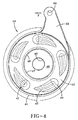
- Such brakes include a rotatable actuator and a stationary actuator, each of which have depressions which are circumferentially spaced around an axis. Steel balls are held within these depressions, and when the rotatable actuator is caused to rotate, the balls roll gradually along the depressions. This in turn causes the rotatable actuator to move axially away from the stationary actuator thereby applying a braking force to a disc assembly.
- These brakes are relatively simple in design because they do not require complex hydraulic mechanisms. Thus, the brakes are relatively dependable and easy to service and operate. Still some deficiencies exist in prior art ball ramp brakes.
- the entire disc assembly is free to slide axially so that when an axial force is applied to the disc assembly via the rotatable actuator, the discs are clamped together and the rotatable discs urge the stationary discs to rotate. Because the stationary discs are coupled to the housing, they are prevented from relative rotation, and a braking torque is applied to the rotating shaft. Yet because of the relative tolerances and the nature of the engagement between the stationary discs and the pins, a certain amount of clearance is necessary between the pin and stationary discs, and this clearance allows for a small degree of rotation. Thus, when the rotatable and stationary discs are caused to engage each other, the stationary discs will rotate slightly, until they fully engage the pin, which restricts any further rotation.
- prior art brakes of this design are inefficient because, as the rotatable actuator is rotated, friction is created between the rotatable actuator and the stationary disc proximate thereto. Thus, much of the force applied by the rotatable actuator is absorbed due to the friction, causing a loss in braking efficiency.
- a brake in accordance with the present invention is adapted to be rotationally coupled with an output shaft.
- the brake includes a housing having a first surface.
- the first surface includes a plurality of depressions which are circumferentially spaced about an axis.
- a rotatable actuator includes a second surface which has a plurality of depressions which are circumferentially spaced about the axis.
- the first and second surface depressions are adjacent to and face each other, and are adapted to carry one of a plurality of balls therebetween.
- At least one biasing means is centered about the axis and adapted to bias the rotatable actuator toward the housing.
- the housing includes a boss which projects into the chamber and is centered on an axis.
- a rotatable actuator is received in the chamber and is rotatable about the axis.
- the rotatable actuator includes a body portion and a central circumferential flange which extends radially inward relative to the body portion: The central circumferential flange defines a central aperture.
- a spring is included.
- a means is positioned proximate to the axial end of the boss to retain the spring against the circumferential flange.
- the boss is received through the aperture and a spring is carried by the boss and axially confined between the circumferential flange and the retaining means.
- a brake for applying a braking force to an external shaft includes a housing which defines a chamber.
- the housing includes a plurality of depressions which are circumferentially spaced around an axis.
- a rotatable actuator is received in the chamber and includes a plurality of depressions circumferentially spaced around the axis.
- the housing depressions face the rotatable actuator depressions and each matching pair of depressions receive a ball therebetween.
- a spring under compression is positioned centrally about the axis.
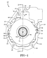
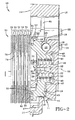
- housing 11 provides a cavity 24 which is formed radially interior of stationary surface 18. Cavity 24 projects into end wall 12 and may be generally cylindrical, centered about axis 22. A boss 25 is disposed at least partially within cavity 24 and projects axially from end wall 12. Boss 25 is centered on axis 22 and may be tapered. As is evident from Fig. 2, boss 25 terminates at a top surface 26 which is relatively further from end wall 12 than stationary surface 18. Boss 25 is provided with a threaded hole 27 which is aligned with axis 22 and extends from top surface 26 axially into boss 25. Threaded hole 27 is adapted to receive a screw 28 which includes a threaded portion 29 and a head 30. A boss washer 31 is secured between the head 30 and top surface 26 when the screw 28 is received in threaded hole 27.
- springs 50 are achieved through a simplified method. Rotatable actuator 40 and balls 23 are placed within chamber 17 in the previously described orientation. Spring 50 is then positioned within bore 46. Retaining washer 51 and boss washer 31 are positioned on the end of spring 50 opposed to flange 48. Screw 28 is then inserted into threaded hole 27. Prior to rotation of screw 28, ;no tension is realized on spring 50. As screw 28 is tightened, thus moving boss washer 31 and retaining washer 51 axially toward end wall 12, spring 50 is compressed. Spring 50 may be sized such that once screw 28 is fully tightened, thereby securing boss washer 31 between head 30 and top surface 26, the optimal compression is achieved.
Landscapes
- Engineering & Computer Science (AREA)
- General Engineering & Computer Science (AREA)
- Mechanical Engineering (AREA)
- Braking Arrangements (AREA)
Applications Claiming Priority (1)
| Application Number | Priority Date | Filing Date | Title |
|---|---|---|---|
| US11/314,449 US7735612B2 (en) | 2005-12-22 | 2005-12-22 | Ball ramp brake |
Publications (3)
| Publication Number | Publication Date |
|---|---|
| EP1801449A2 true EP1801449A2 (de) | 2007-06-27 |
| EP1801449A3 EP1801449A3 (de) | 2008-08-27 |
| EP1801449B1 EP1801449B1 (de) | 2012-08-01 |
Family
ID=37875717
Family Applications (1)
| Application Number | Title | Priority Date | Filing Date |
|---|---|---|---|
| EP06026559A Active EP1801449B1 (de) | 2005-12-22 | 2006-12-21 | Ball-Ramp-Bremse |
Country Status (2)
| Country | Link |
|---|---|
| US (1) | US7735612B2 (de) |
| EP (1) | EP1801449B1 (de) |
Families Citing this family (8)
| Publication number | Priority date | Publication date | Assignee | Title |
|---|---|---|---|---|
| US8235183B2 (en) * | 2008-02-25 | 2012-08-07 | Ausco Products, Inc. | Ball ramp brake |
| JP5532246B2 (ja) * | 2010-09-30 | 2014-06-25 | 日立オートモティブシステムズ株式会社 | 推力発生装置、ディスクブレーキ及びスタビライザ |
| PL2570379T3 (pl) * | 2011-09-15 | 2016-04-29 | Epsilon Kran Gmbh | Układ przegubowy obrotowy |
| US9163680B2 (en) * | 2012-09-18 | 2015-10-20 | Foster-Miller, Inc. | Powerless brake |
| TWM525318U (zh) * | 2015-07-24 | 2016-07-11 | Hsin-Fa Wang | 碟式煞車 |
| US9630086B1 (en) | 2015-12-08 | 2017-04-25 | John M. Wahe | Leveling device, system and method |
| US11846332B2 (en) | 2022-03-01 | 2023-12-19 | Ausco Products, Inc. | Open-ended, spring applied, hydraulically released brake with full alignment of components |
| CN119267458A (zh) * | 2024-09-10 | 2025-01-07 | 中国第一汽车股份有限公司 | 离合器执行机构及车辆 |
Citations (1)
| Publication number | Priority date | Publication date | Assignee | Title |
|---|---|---|---|---|
| EP1039165A2 (de) | 1999-03-23 | 2000-09-27 | Eaton Corporation | Getriebeträgheitsbremse mit Ölblockierring |
Family Cites Families (10)
| Publication number | Priority date | Publication date | Assignee | Title |
|---|---|---|---|---|
| SE7414359L (sv) * | 1974-11-15 | 1976-05-17 | Bofors Ab | Sett att kyla en vat lamellkoppling jemte herfor avsedd kopplingslamell |
| US4372433A (en) * | 1980-04-14 | 1983-02-08 | Briggs & Stratton Corporation | Combination clutch/brake mechanism |
| US6374958B1 (en) * | 1999-03-31 | 2002-04-23 | Tokico Ltd. | Motor-driven disk brake |
| US6491140B2 (en) * | 2000-03-15 | 2002-12-10 | Tokico, Ltd. | Electric disc brake |
| JP4560873B2 (ja) * | 2000-03-21 | 2010-10-13 | いすゞ自動車株式会社 | カウンタシャフトブレーキの潤滑装置 |
| FR2817309B1 (fr) | 2000-11-28 | 2003-01-10 | Bosch Gmbh Robert | Cylindre de frein a disque avec mecanisme de frein de parc, frein a disque comportant un tel cylindre et jeu d'au moins deux disques |
| FR2817218B1 (fr) * | 2000-11-28 | 2003-01-10 | Bosch Gmbh Robert | Cylindre de frein a disque avec mecanisme de frein de parc |
| FR2828538B1 (fr) * | 2001-08-08 | 2003-10-24 | Bosch Gmbh Robert | Cylindre de frein a actionnement mecanique et hydraulique de dimensions reduites et frein de vehicule automobile comprenant un tel cylindre |
| JP4304418B2 (ja) * | 2002-02-28 | 2009-07-29 | 株式会社日立製作所 | 電動ディスクブレーキ |
| US20050217949A1 (en) * | 2004-04-06 | 2005-10-06 | Makoto Ohta | Disc brake caliper with parking input mechanism |
-
2005
- 2005-12-22 US US11/314,449 patent/US7735612B2/en not_active Expired - Lifetime
-
2006
- 2006-12-21 EP EP06026559A patent/EP1801449B1/de active Active
Patent Citations (1)
| Publication number | Priority date | Publication date | Assignee | Title |
|---|---|---|---|---|
| EP1039165A2 (de) | 1999-03-23 | 2000-09-27 | Eaton Corporation | Getriebeträgheitsbremse mit Ölblockierring |
Also Published As
| Publication number | Publication date |
|---|---|
| US7735612B2 (en) | 2010-06-15 |
| EP1801449A3 (de) | 2008-08-27 |
| US20070144838A1 (en) | 2007-06-28 |
| EP1801449B1 (de) | 2012-08-01 |
Similar Documents
| Publication | Publication Date | Title |
|---|---|---|
| US11780419B2 (en) | Electric park brake with electromagnetic brake | |
| JP4698952B2 (ja) | ディスクブレーキの力伝達装置 | |
| EP1757836B1 (de) | Scheibenbremsvorrichtung | |
| US9835211B2 (en) | Brake assembly | |
| CN113915265B (zh) | 致动机构 | |
| US7735612B2 (en) | Ball ramp brake | |
| CN110873135A (zh) | 一种微轨车辆及其电磁制动器 | |
| US10644566B2 (en) | Motor with a motor brake | |
| US11136010B2 (en) | Motor with a cone clutch motor brake | |
| CN101349311B (zh) | 盘式制动装置 | |
| US20090095581A1 (en) | Floating disc brake | |
| US7040462B2 (en) | Ball ramp caliper brake | |
| FI114503B (fi) | Momenttiohjatusti toimiva jarru | |
| KR100836460B1 (ko) | 클러치용 액츄에이터와 이를 구비한 트랜스퍼 케이스 | |
| EP1917450B1 (de) | Selbstausrichtendes bremskit | |
| US20130299287A1 (en) | Vehicle disc brake assembly having a mechanically actuated parking brake | |
| JP4155869B2 (ja) | パーキング機構付ディスクブレーキ | |
| CN114278688A (zh) | 制动器组件及调整方法 | |
| CN107110253B (zh) | 具有偏置凸轮从动件的鼓式制动器s形凸轮 | |
| JP2006250325A (ja) | ディスクブレーキ装置 | |
| JP2005042753A (ja) | ディスクブレーキ装置 | |
| JPH0526360Y2 (de) | ||
| JPS6039548Y2 (ja) | プレ−トデイスクブレ−キ | |
| JP2018501422A (ja) | スリーブインサートを有する油圧装置 | |
| JP2007113669A (ja) | パーキング機構付湿式ディスクブレーキ |
Legal Events
| Date | Code | Title | Description |
|---|---|---|---|
| PUAI | Public reference made under article 153(3) epc to a published international application that has entered the european phase |
Free format text: ORIGINAL CODE: 0009012 |
|
| AK | Designated contracting states |
Kind code of ref document: A2 Designated state(s): AT BE BG CH CY CZ DE DK EE ES FI FR GB GR HU IE IS IT LI LT LU LV MC NL PL PT RO SE SI SK TR |
|
| AX | Request for extension of the european patent |
Extension state: AL BA HR MK YU |
|
| PUAL | Search report despatched |
Free format text: ORIGINAL CODE: 0009013 |
|
| AK | Designated contracting states |
Kind code of ref document: A3 Designated state(s): AT BE BG CH CY CZ DE DK EE ES FI FR GB GR HU IE IS IT LI LT LU LV MC NL PL PT RO SE SI SK TR |
|
| AX | Request for extension of the european patent |
Extension state: AL BA HR MK RS |
|
| 17P | Request for examination filed |
Effective date: 20081113 |
|
| 17Q | First examination report despatched |
Effective date: 20090109 |
|
| AKX | Designation fees paid |
Designated state(s): AT BE BG CH CY CZ DE DK EE ES FI FR GB GR HU IE IS IT LI LT LU LV MC NL PL PT RO SE SI SK TR |
|
| GRAP | Despatch of communication of intention to grant a patent |
Free format text: ORIGINAL CODE: EPIDOSNIGR1 |
|
| GRAS | Grant fee paid |
Free format text: ORIGINAL CODE: EPIDOSNIGR3 |
|
| GRAA | (expected) grant |
Free format text: ORIGINAL CODE: 0009210 |
|
| AK | Designated contracting states |
Kind code of ref document: B1 Designated state(s): AT BE BG CH CY CZ DE DK EE ES FI FR GB GR HU IE IS IT LI LT LU LV MC NL PL PT RO SE SI SK TR |
|
| REG | Reference to a national code |
Ref country code: GB Ref legal event code: FG4D |
|
| REG | Reference to a national code |
Ref country code: CH Ref legal event code: EP Ref country code: AT Ref legal event code: REF Ref document number: 568861 Country of ref document: AT Kind code of ref document: T Effective date: 20120815 |
|
| REG | Reference to a national code |
Ref country code: IE Ref legal event code: FG4D |
|
| REG | Reference to a national code |
Ref country code: DE Ref legal event code: R096 Ref document number: 602006031038 Country of ref document: DE Effective date: 20121011 |
|
| REG | Reference to a national code |
Ref country code: SE Ref legal event code: TRGR |
|
| REG | Reference to a national code |
Ref country code: NL Ref legal event code: VDEP Effective date: 20120801 |
|
| REG | Reference to a national code |
Ref country code: AT Ref legal event code: MK05 Ref document number: 568861 Country of ref document: AT Kind code of ref document: T Effective date: 20120801 |
|
| REG | Reference to a national code |
Ref country code: LT Ref legal event code: MG4D Effective date: 20120801 |
|
| PG25 | Lapsed in a contracting state [announced via postgrant information from national office to epo] |
Ref country code: AT Free format text: LAPSE BECAUSE OF FAILURE TO SUBMIT A TRANSLATION OF THE DESCRIPTION OR TO PAY THE FEE WITHIN THE PRESCRIBED TIME-LIMIT Effective date: 20120801 Ref country code: CY Free format text: LAPSE BECAUSE OF FAILURE TO SUBMIT A TRANSLATION OF THE DESCRIPTION OR TO PAY THE FEE WITHIN THE PRESCRIBED TIME-LIMIT Effective date: 20120801 Ref country code: LT Free format text: LAPSE BECAUSE OF FAILURE TO SUBMIT A TRANSLATION OF THE DESCRIPTION OR TO PAY THE FEE WITHIN THE PRESCRIBED TIME-LIMIT Effective date: 20120801 Ref country code: IS Free format text: LAPSE BECAUSE OF FAILURE TO SUBMIT A TRANSLATION OF THE DESCRIPTION OR TO PAY THE FEE WITHIN THE PRESCRIBED TIME-LIMIT Effective date: 20121201 Ref country code: FI Free format text: LAPSE BECAUSE OF FAILURE TO SUBMIT A TRANSLATION OF THE DESCRIPTION OR TO PAY THE FEE WITHIN THE PRESCRIBED TIME-LIMIT Effective date: 20120801 |
|
| PG25 | Lapsed in a contracting state [announced via postgrant information from national office to epo] |
Ref country code: BE Free format text: LAPSE BECAUSE OF FAILURE TO SUBMIT A TRANSLATION OF THE DESCRIPTION OR TO PAY THE FEE WITHIN THE PRESCRIBED TIME-LIMIT Effective date: 20120801 Ref country code: PL Free format text: LAPSE BECAUSE OF FAILURE TO SUBMIT A TRANSLATION OF THE DESCRIPTION OR TO PAY THE FEE WITHIN THE PRESCRIBED TIME-LIMIT Effective date: 20120801 Ref country code: PT Free format text: LAPSE BECAUSE OF FAILURE TO SUBMIT A TRANSLATION OF THE DESCRIPTION OR TO PAY THE FEE WITHIN THE PRESCRIBED TIME-LIMIT Effective date: 20121203 Ref country code: SI Free format text: LAPSE BECAUSE OF FAILURE TO SUBMIT A TRANSLATION OF THE DESCRIPTION OR TO PAY THE FEE WITHIN THE PRESCRIBED TIME-LIMIT Effective date: 20120801 Ref country code: GR Free format text: LAPSE BECAUSE OF FAILURE TO SUBMIT A TRANSLATION OF THE DESCRIPTION OR TO PAY THE FEE WITHIN THE PRESCRIBED TIME-LIMIT Effective date: 20121102 Ref country code: LV Free format text: LAPSE BECAUSE OF FAILURE TO SUBMIT A TRANSLATION OF THE DESCRIPTION OR TO PAY THE FEE WITHIN THE PRESCRIBED TIME-LIMIT Effective date: 20120801 |
|
| PG25 | Lapsed in a contracting state [announced via postgrant information from national office to epo] |
Ref country code: NL Free format text: LAPSE BECAUSE OF FAILURE TO SUBMIT A TRANSLATION OF THE DESCRIPTION OR TO PAY THE FEE WITHIN THE PRESCRIBED TIME-LIMIT Effective date: 20120801 |
|
| PG25 | Lapsed in a contracting state [announced via postgrant information from national office to epo] |
Ref country code: ES Free format text: LAPSE BECAUSE OF FAILURE TO SUBMIT A TRANSLATION OF THE DESCRIPTION OR TO PAY THE FEE WITHIN THE PRESCRIBED TIME-LIMIT Effective date: 20121112 Ref country code: DK Free format text: LAPSE BECAUSE OF FAILURE TO SUBMIT A TRANSLATION OF THE DESCRIPTION OR TO PAY THE FEE WITHIN THE PRESCRIBED TIME-LIMIT Effective date: 20120801 Ref country code: RO Free format text: LAPSE BECAUSE OF FAILURE TO SUBMIT A TRANSLATION OF THE DESCRIPTION OR TO PAY THE FEE WITHIN THE PRESCRIBED TIME-LIMIT Effective date: 20120801 Ref country code: EE Free format text: LAPSE BECAUSE OF FAILURE TO SUBMIT A TRANSLATION OF THE DESCRIPTION OR TO PAY THE FEE WITHIN THE PRESCRIBED TIME-LIMIT Effective date: 20120801 Ref country code: CZ Free format text: LAPSE BECAUSE OF FAILURE TO SUBMIT A TRANSLATION OF THE DESCRIPTION OR TO PAY THE FEE WITHIN THE PRESCRIBED TIME-LIMIT Effective date: 20120801 |
|
| PG25 | Lapsed in a contracting state [announced via postgrant information from national office to epo] |
Ref country code: SK Free format text: LAPSE BECAUSE OF FAILURE TO SUBMIT A TRANSLATION OF THE DESCRIPTION OR TO PAY THE FEE WITHIN THE PRESCRIBED TIME-LIMIT Effective date: 20120801 |
|
| PLBE | No opposition filed within time limit |
Free format text: ORIGINAL CODE: 0009261 |
|
| STAA | Information on the status of an ep patent application or granted ep patent |
Free format text: STATUS: NO OPPOSITION FILED WITHIN TIME LIMIT |
|
| 26N | No opposition filed |
Effective date: 20130503 |
|
| PG25 | Lapsed in a contracting state [announced via postgrant information from national office to epo] |
Ref country code: BG Free format text: LAPSE BECAUSE OF FAILURE TO SUBMIT A TRANSLATION OF THE DESCRIPTION OR TO PAY THE FEE WITHIN THE PRESCRIBED TIME-LIMIT Effective date: 20121101 Ref country code: MC Free format text: LAPSE BECAUSE OF NON-PAYMENT OF DUE FEES Effective date: 20121231 |
|
| REG | Reference to a national code |
Ref country code: CH Ref legal event code: PL |
|
| REG | Reference to a national code |
Ref country code: DE Ref legal event code: R097 Ref document number: 602006031038 Country of ref document: DE Effective date: 20130503 |
|
| REG | Reference to a national code |
Ref country code: IE Ref legal event code: MM4A |
|
| REG | Reference to a national code |
Ref country code: FR Ref legal event code: ST Effective date: 20130830 |
|
| PG25 | Lapsed in a contracting state [announced via postgrant information from national office to epo] |
Ref country code: IE Free format text: LAPSE BECAUSE OF NON-PAYMENT OF DUE FEES Effective date: 20121221 Ref country code: CH Free format text: LAPSE BECAUSE OF NON-PAYMENT OF DUE FEES Effective date: 20121231 Ref country code: LI Free format text: LAPSE BECAUSE OF NON-PAYMENT OF DUE FEES Effective date: 20121231 |
|
| PG25 | Lapsed in a contracting state [announced via postgrant information from national office to epo] |
Ref country code: FR Free format text: LAPSE BECAUSE OF NON-PAYMENT OF DUE FEES Effective date: 20130102 |
|
| PG25 | Lapsed in a contracting state [announced via postgrant information from national office to epo] |
Ref country code: TR Free format text: LAPSE BECAUSE OF FAILURE TO SUBMIT A TRANSLATION OF THE DESCRIPTION OR TO PAY THE FEE WITHIN THE PRESCRIBED TIME-LIMIT Effective date: 20120801 |
|
| PG25 | Lapsed in a contracting state [announced via postgrant information from national office to epo] |
Ref country code: LU Free format text: LAPSE BECAUSE OF NON-PAYMENT OF DUE FEES Effective date: 20121221 |
|
| PG25 | Lapsed in a contracting state [announced via postgrant information from national office to epo] |
Ref country code: HU Free format text: LAPSE BECAUSE OF FAILURE TO SUBMIT A TRANSLATION OF THE DESCRIPTION OR TO PAY THE FEE WITHIN THE PRESCRIBED TIME-LIMIT Effective date: 20061221 |
|
| REG | Reference to a national code |
Ref country code: DE Ref legal event code: R082 Ref document number: 602006031038 Country of ref document: DE Representative=s name: PATENTANWALTSKANZLEI MEYER, DE |
|
| PGFP | Annual fee paid to national office [announced via postgrant information from national office to epo] |
Ref country code: SE Payment date: 20201211 Year of fee payment: 15 |
|
| REG | Reference to a national code |
Ref country code: SE Ref legal event code: EUG |
|
| PG25 | Lapsed in a contracting state [announced via postgrant information from national office to epo] |
Ref country code: SE Free format text: LAPSE BECAUSE OF NON-PAYMENT OF DUE FEES Effective date: 20211222 |
|
| PGFP | Annual fee paid to national office [announced via postgrant information from national office to epo] |
Ref country code: DE Payment date: 20231024 Year of fee payment: 18 |
|
| REG | Reference to a national code |
Ref country code: DE Ref legal event code: R119 Ref document number: 602006031038 Country of ref document: DE |
|
| PG25 | Lapsed in a contracting state [announced via postgrant information from national office to epo] |
Ref country code: DE Free format text: LAPSE BECAUSE OF NON-PAYMENT OF DUE FEES Effective date: 20250701 |
|
| PGFP | Annual fee paid to national office [announced via postgrant information from national office to epo] |
Ref country code: GB Payment date: 20251001 Year of fee payment: 20 |
|
| PGFP | Annual fee paid to national office [announced via postgrant information from national office to epo] |
Ref country code: IT Payment date: 20251121 Year of fee payment: 20 |