EP1801598A2 - Multimeter - Google Patents
Multimeter Download PDFInfo
- Publication number
- EP1801598A2 EP1801598A2 EP06020080A EP06020080A EP1801598A2 EP 1801598 A2 EP1801598 A2 EP 1801598A2 EP 06020080 A EP06020080 A EP 06020080A EP 06020080 A EP06020080 A EP 06020080A EP 1801598 A2 EP1801598 A2 EP 1801598A2
- Authority
- EP
- European Patent Office
- Prior art keywords
- multimeter according
- multimeter
- locking device
- angle lever
- measuring range
- Prior art date
- Legal status (The legal status is an assumption and is not a legal conclusion. Google has not performed a legal analysis and makes no representation as to the accuracy of the status listed.)
- Granted
Links
Images





Classifications
-
- G—PHYSICS
- G01—MEASURING; TESTING
- G01R—MEASURING ELECTRIC VARIABLES; MEASURING MAGNETIC VARIABLES
- G01R15/00—Details of measuring arrangements of the types provided for in groups G01R17/00 - G01R29/00, G01R33/00 - G01R33/26 or G01R35/00
- G01R15/002—Switches for altering the measuring range or for multitesters
Definitions
- the invention relates to a multimeter with a housing, which has at least three input terminals designed as sockets for connecting two test leads, with the further features of the preamble 1.
- Such a multimeter is off EP 0 474 086 B1 known.
- the well-known multimeter is characterized in that it has a measuring range switch, which is to bring in one of the selected measured variables associated switching position, wherein the measuring range switch a mechanically acting locking device is coupled, which allows blocking certain input terminals in such a way that one over the measuring leads a measuring signal receiving contact only each of the input terminals can be made, which is associated with a measured variable that corresponds to the set with the Meß Schlschalter measurement.
- the locking device is a plate-like Sperrkulisse, which is adapted to the nature and structure of the associated Meß Kunststoffsschalters and in which a recess is provided whose positioning with the switching position of the Meß Kunststoffsschalters so corresponds that the recess respectively the receiving channel of the socket enable the trained input terminal assigned to the measured variable set with the measuring range switch.
- the invention has for its object to form a multimeter with the features of the preamble of claim 1 such that the locking device is simplified and in particular reduced in size and still a plurality of input terminals can be blocked by them.
- the locking device in the manner of a substantially mounted in its apex, pivotable angle lever, wherein the end portions of the strip-like angle leg can be brought by the measuring range switch in an aligned with the input terminals to be closed position.
- a locking device is simple and inexpensive to produce in terms of material, it can be easily mounted and claimed within the housing only relatively little space, since the arranged between the two legs free space can be exploited to arrange an input terminal, of the two End portions of the angle leg does not have to be closed, in particular a "Com" connection of the multimeter.
- a switchable with an adjustment of the Meß Schlschalters engaging switching projection is arranged on the angle lever, wherein the angle lever is symmetrical relative to the switching projection and by the two legs and the switching projection quasi a tripartite star is formed.
- Such a part is also easy to manufacture and easy to assemble. Particularly compact conditions within the multimeter housing with respect to the Sperrkulissenanowski arise when the opening of the central input terminal, the bearing point of the angle lever and the pivot point of the Meß Schlalters lie in line.
- a secure and stable engagement between the switching projection and the measuring range switch is obtained when the switching projection is form-fitting coupled in two respects to the rotatable measuring range switch, namely on the one hand by a tip which engages in a MitauerausEnglishung the Meß Kunststoffsschalters and by a groove having a in the recess of the Meß Kunststoffsschalters arranged catch projection engages around.
- the blocking device is arranged in a housing sealed in a watertight manner. Then the multimeter is also sufficient, despite the Arrangement of a Sperrkulissenan ever, high demands on water resistance, which is particularly advantageous in terms of reliability of the device.
- the housing of the locking device is formed by the locking device laterally embracing side wall and a quasi an intermediate wall forming Buchsen33wandung, are arranged integrally with the input terminals aligned contact sleeves, in which the contacts of the sockets are welded.
- the implementation of leading into the interior of the multimeter housing lines is waterproof.
- the Buchsenabowandung is welded to the side wall of the housing, by attaching the Buchseneseldung simultaneously the shift gate is pivotally mounted in their storage.
- the claims 13 - 15 relate to reinforcing elements in the range of the angle lever, which allow a particularly high load on the blocking gate.
- the multimeter 1 has a housing 2, which is composed of two housing shells 3, 4.
- the upper housing shell 3 are designed as three sockets 5 input terminals 6 are provided, which serve for connecting measuring leads not shown.
- a measuring range switch 7 is provided, which is to be brought by rotation in one of the selected measured variables associated switching position.
- a mechanically acting locking device 8 is coupled, which allows blocking of the two outer input terminals 6 ', 6 "in such a way that the plug of a measuring line can only be inserted into a socket, which is set with the Meß Suitesschalter 7 measured variable equivalent.
- the locking device 8 results in detail in particular from Figures 2-6, wherein the locking device 8 is shown together with the measuring range switch 7 from the inside of the housing forth in different switching positions.
- the locking device 8 is formed in the manner of a substantially mounted in its apex 9 pivotable angle lever 10, wherein the end portions 11 of the strip-like angle leg 12 can be brought by the measuring range switch 7 in a position to be closed with the input terminals 6 ', 6 "aligned position
- the angle lever 10 is arranged with the adjusting element 13 of the range switch 7 engageable switching projection 14, wherein the angle lever 10 is formed symmetrically with respect to the switching projection 14 and by the two legs 12 and the switching projection 14 is a tripartite star is formed in the drawing figures is clearly seen that the two angle legs 12 of the angle lever 10, the middle input terminal 6 '' 'overlap, so that it can not be closed by the end portions 11 of the angle leg 12.
- the switching projection 14 has a tip 16 which engages in a Mit predominantlyausEnglishung the rotary measuring range switch 7.
- a groove 18 is arranged in the region of the tip 16, which surrounds a driving projection 19 arranged in the recess 17 of the measuring range switch 7.
- the positive-locking elements 16-19 which are required to adjust the locking device 8 as a result of a rotation of the measuring range switch 7, is shown again in detail in FIGS. 7-10.
- the locking device 8 is arranged in a waterproof encapsulated socket housing 20, wherein the Socket housing 20 by a locking device 8 laterally embracing side wall 21 and a Buchsenarmewandung 22 is formed on the integrally formed with the input terminals contact sleeves 23 are formed.
- the contacts of the sockets may be welded into the contact sleeves 23, but it is also possible that the contacts on circumferential seals of the bushings with double undercut and as shown in Figure 14, are sealed.
- the Buchsenarmewandung 22 is welded to the side wall 21 of the housing 20 ultrasonic and thus tightly connected.
- the angle lever 10 engages with a sleeve-like bearing element 35 a rotary bearing projection 36, wherein the rotary bearing element is mounted in a recess of the Buchsenarriwandung 22.
Landscapes
- Physics & Mathematics (AREA)
- General Physics & Mathematics (AREA)
- Measuring Instrument Details And Bridges, And Automatic Balancing Devices (AREA)
- Amplifiers (AREA)
- Gyroscopes (AREA)
- Details Of Connecting Devices For Male And Female Coupling (AREA)
Abstract
Description
- Die Erfindung betrifft ein Multimeter mit einem Gehäuse, das mindestens drei als Steckbuchsen ausgeführte Eingangsanschlüsse zum Anschließen von zwei Meßleitungen aufweist, mit den weiteren Merkmalen des Oberbegriffes 1.
- Ein derartiges Multimeter ist aus
EP 0 474 086 B1 bekannt. Das bekannte Multimeter zeichnet sich dadurch aus, daß es einen Meßbereichsschalter aufweist, der in eine der gewählten Meßgrößen zugeordnete Schaltstellung zu bringen ist, wobei mit dem Meßbereichsschalter eine mechanisch wirkende Sperrvorrichtung gekoppelt ist, die eine Sperrung bestimmter Eingangsanschlüsse in der Weise erlaubt, daß eine über die Meßleitungen ein Meßsignal aufnehmende Kontaktierung nur jeweils der Eingangsanschlüsse erfolgen kann, denen eine Meßgröße zugeordnet ist, die der mit dem Meßbereichsschalter eingestellten Meßgröße entspricht. Bei diesem Stand der Technik ist die Sperrvorrichtung eine plattenartige Sperrkulisse, die der Art und dem Aufbau des zugehörigen Meßbereichsschalters angepaßt ist und in der eine Aussparung vorgesehen ist, deren Positionierung mit der Schaltstellung des Meßbereichsschalters so korrespondiert, daß die Aussparung jeweils den Aufnahmekanal des als Steckbuchse ausgebildeten Eingangsanschlusses freigeben, der mit dem Meßbereichsschalter eingestellten Meßgröße zugeordnet ist. - Darüber hinaus ist aus dem
japanischen Gebrauchsmuster SHO 62-39333 - Der Erfindung liegt die Aufgabe zugrunde, ein Multimeter mit den Merkmalen des Oberbegriffes des Anspruches 1 derart auszubilden, daß die Sperrvorrichtung vereinfacht und insbesondere verkleinert ist und trotzdem eine Mehrzahl von Eingangsanschlüssen durch sie versperrt werden kann.
- Diese Aufgabe wird durch die kennzeichnenden Merkmale des Anspruches 1 gelöst, vorteilhafte Weiterbildungen der Erfindung ergeben sich aus den Unteransprüchen 2 - 16.
- Als Kern der Erfindung wird es angesehen, die Sperrvorrichtung nach Art eines im wesentlichen in seinem Scheitelpunkt gelagerten, verschwenkbaren Winkelhebels auszubilden, wobei die Endbereiche der streifenartig ausgebildeten Winkelschenkel durch den Meßbereichsschalter in eine mit den zu verschließenden Eingangsanschlüssen fluchtende Stellung gebracht werden kann. Eine derartige Ausführungsform einer Sperrvorrichtung ist einfach und preisgünstig hinsichtlich des Materials herstellbar, sie kann einfach montiert werden und beansprucht innerhalb des Gehäuses nur relativ wenig Platz, da der zwischen den beiden Schenkeln angeordnete Freibereich ausgenutzt werden kann, um einen Eingangsanschluß anzuordnen, der von den beiden Endbereichen der Winkelschenkel nicht verschlossen werden muß, insbesondere einen "Com"-Anschluß des Multimeters.
- Gemäß einer Weiterbildung der Erfindung ist an dem Winkelhebel ein mit einem Verstellelement des Meßbereichsschalters in Eingriff bringbarer Schaltvorsprung angeordnet, wobei der Winkelhebel bezogen auf den Schaltvorsprung symmetrisch ausgebildet ist und durch die beiden Schenkel sowie den Schaltvorsprung quasi ein dreigliedriger Stern gebildet wird. Ein derartiges Teil ist ebenfalls leicht herzustellen und leicht zu montieren. Besonders kompakte Verhältnisse innerhalb des Multimetergehäuses bezüglich der Sperrkulissenanordnung ergeben sich dann, wenn die Öffnung des mittleren Eingangsanschlusses, der Lagerpunkt des Winkelhebels und der Drehpunkt des Meßbereichsschalters auf einer Linie liegen. Einen sicheren und stabilen Eingriff zwischen dem Schaltvorsprung und dem Meßbereichsschalter ergibt sich dann, wenn der Schaltvorsprung formschlußartig in zweifacher Hinsicht an den drehbaren Meßbereichsschalter gekoppelt ist, nämlich einerseits durch eine Spitze, die in eine Mitnehmerausnehmung des Meßbereichsschalters eingreift und durch eine Nut, die einen in der Ausnehmung des Meßbereichsschalters angeordneten Mitnehmervorsprung umgreift.
- Ganz besonders vorteilhaft ist es, wenn die Sperrvorrichtung in einem wasserdicht gekapselten Gehäuse angeordnet ist. Dann genügt das Multimeter auch relativ, trotz der Anordnung einer Sperrkulissenanordnung, hohen Anforderungen an Wasserdichtigkeit, die im Hinblick auf die Betriebssicherheit des Gerätes von besonderem Vorteil ist. Das Gehäuse der Sperrvorrichtung wird durch eine die Sperrvorrichtung seitlich umgreifende Seitenwandung und eine quasi eine Zwischenwandung bildende Buchsenträgerwandung gebildet, an der einstückig mit den Eingangsanschlüssen fluchtende Kontakthülsen angeordnet sind, in die die Kontakte der Buchsen eingeschweißt sind. Die Durchführung der in den Innenbereich des Multimetergehäuses führenden Leitungen ist dabei wasserdicht ausgeführt. Die Buchsenträgerwandung ist mit der Seitenwandung des Gehäuses verschweißt, durch die Befestigung der Buchsenträgerwandung wird gleichzeitig die Schaltkulisse in ihrer Lagerung schwenkbefestigt.
- Die Ansprüche 13 - 15 betreffen Verstärkungselemente im Bereich des Winkelhebels, die eine besonders hohe Belastung der Sperrkulisse erlauben.
- Durch die Merkmale des Anspruches 16 wird eine Stabilisierung des wasserdicht gekapselten Gehäuses der Sperrvorrichtung sichergestellt, auch wenn über eingesteckte Kontaktstecker von Meßleitungen relativ hohe mechanische Scherkräfte auf das Multimeter ausgeübt werden.
- Die Erfindung ist anhand vorteilhafter Ausführungsbeispiele in den Zeichnungsfiguren näher erläutert. Diese zeigen
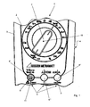
- Fig. 1
- eine Außenansicht des Multimeters mit drei Eingangsanschlüssen, von denen die beiden außenliegenden Eingangsanschlüsse durch die Sperrvorrichtung sperrbar sind;
- Fig. 2
- eine Innenansicht der Gehäuseoberschale mit der als verschwenkbarer Winkelhebel ausgebildeten Sperrvorrichtung mit Meßbereichsschalter in einer ersten Schaltstellung;
- Fig. 3
- eine Darstellung gemäß Fig. 2 in einer zweiten Schaltstellung;
- Fig. 4
- eine Darstellung gemäß Fig. 2 und 3 in einer Zwischenstellung;
- Fig. 5
- eine Darstellung gemäß Fig. 2 - 4 in einer dritten Schaltstellung;
- Fig. 6
- eine Darstellung gemäß Fig. 2 - 5 in einer vierten Schaltstellung;
- Fig. 7
- eine Schnittdarstellung gemäß Schnittlinie A-A gemäß Fig. 4;
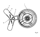
- Fig. 8
- eine weitere Schnittdarstellung gemäß Schnittlinie B-B in Fig. 5;
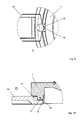
- Fig. 9
- eine Detailansicht des Formschlußeingriffes gemäß Bereich C in Fig. 4;
- Fig. 10
- eine Detaildarstellung des Formschlusses gemäß Bereich D in Fig. 7;
- Fig. 11
- eine Innenansicht des Multimeters mit montierter Buchsenträgerwandung;
- Fig. 12
- einen Schnitt gemäß Schnittlinie A-A in Fig. 11;
- Fig. 13
- eine Darstellung zur Erläuterung der Abdichtung der Buchsenträgerwandung gemäß Detail B in Fig. 12;
- Fig. 14
- eine Detailansicht der Buchsenabdichtung gemäß Bereich C in Fig. 12;
- Fig. 15
- eine perspektivische Ansicht der in die Seitenwandungen eingelegten Sperrvorrichtung ohne aufgesetzte Buchsenträgerwandung.
- Zunächst wird auf Zeichnungsfigur 1 Bezug genommen. Das Multimeter 1 weist ein Gehäuse 2 auf, das aus zwei Gehäuseschalen 3, 4 zusammengesetzt ist. In der oberen Gehäuseschale 3 sind drei als Steckbuchsen 5 ausgeführte Eingangsanschlüsse 6 vorgesehen, die zum Anschließen von nicht näher dargestellten Meßleitungen dienen. In der Gehäuseoberschale 3 ist ein Meßbereichsschalter 7 vorgesehen, der durch Verdrehen in eine der gewählten Meßgrößen zugeordnete Schaltstellung zu bringen ist. Mit dem Meßbereichsschalter 7 ist eine mechanisch wirkende Sperrvorrichtung 8 gekoppelt, die eine Sperrung der beiden außenliegenden Eingangsanschlüsse 6', 6" in der Weise erlaubt, daß der Stecker einer Meßleitung nur in eine Steckbuchse eingeführt werden kann, die einer mit dem Meßbereichsschalter 7 eingestellten Meßgröße entspricht.
- Die Sperrvorrichtung 8 ergibt sich im Detail insbesondere aus den Figuren 2 - 6, wobei die Sperrvorrichtung 8 zusammen mit dem Meßbereichsschalter 7 von der Gehäuseinnenseite her in unterschiedlichen Schaltstellungen dargestellt ist.
- Die Sperrvorrichtung 8 ist nach Art eines im wesentlichen in seinem Scheitelpunkt 9 gelagerten verschwenkbaren Winkelhebels 10 ausgebildet, wobei die Endbereiche 11 der streifenartigen Winkelschenkel 12 durch den Meßbereichsschalter 7 in eine mit den zu verschließenden Eingangsanschlüssen 6', 6" fluchtende Stellung gebracht werden können. An dem Winkelhebel 10 ist ein mit dem Verstellelement 13 des Meßbereichsschalters 7 in Eingriff bringbarer Schaltvorsprung 14 angeordnet, wobei der Winkelhebel 10 bezogen auf den Schaltvorsprung 14 symmetrisch ausgebildet ist und durch die beiden Schenkel 12 sowie den Schaltvorsprung 14 ein dreigliedriger Stern gebildet wird. In den Zeichnungsfiguren ist deutlich zu sehen, daß die beiden Winkelschenkel 12 des Winkelhebels 10 den mittleren Eingangsanschluß 6''' übergreifen, so daß dieser nicht durch die Endbereiche 11 der Winkelschenkel 12 verschlossen werden kann.
- Die Anordnung des Meßbereichsschalters 7, des Winkelhebels 10 und des mittleren Eingangsanschlusses 6''' ist so getroffen, daß der Lagerpunkt (Scheitelpunkt 9) des Winkelhebels 10, der Drehpunkt 15 des Meßbereichsschalters 7 und die Öffnung des mittleren Eingangsanschlusses 6''' auf einer geraden Linie liegen.
- Der Schaltvorsprung 14 weist eine Spitze 16 auf, die in eine Mitnehmerausnehmung des drehbaren Meßbereichsschalters 7 eingreift. Zusätzlich ist im Bereich der Spitze 16 eine Nut 18 angeordnet, die einen in der Ausnehmung 17 des Meßbereichsschalters 7 angeordneten Mitnehmervorsprung 19 umgreift.
- Die den Formschluß bildenden Elemente 16 - 19, die zu einer Verstellung der Sperrvorrichtung 8 in Folge einer Verdrehung des Meßbereichsschalters 7 erforderlich ist, ist im Detail noch einmal in den Figuren 7 - 10 dargestellt.
- Wie sich insbesondere aus den Zeichnungsfiguren 11 - 15 ergibt, ist die Sperrvorrichtung 8 in einem wasserdicht gekapselten Buchsengehäuse 20 angeordnet, wobei das Buchsengehäuse 20 durch eine die Sperrvorrichtung 8 seitlich umgreifende Seitenwandung 21 und eine Buchsenträgerwandung 22 gebildet ist, an der einstückig mit den Eingangsanschlüssen fluchtende Kontakthülsen 23 angeformt sind. Die Kontakte der Buchsen können in die Kontakthülsen 23 eingeschweißt sein, es besteht aber auch die Möglichkeit, daß die Kontakte über umlaufende Abdichtungen der Buchsen mit doppeltem Hinterschnitt sowie wie dies in Figur 14 gezeigt ist, abgedichtet sind.
- Die Buchsenträgerwandung 22 ist mit der Seitenwandung 21 des Gehäuses 20 Ultraschall verschweißt und damit dicht verbunden.
- Die Endbereiche 11 der Winkelschenkel 12 sind in Seitenbereiche 30 des Buchsengehäuses 20 verschwenkbar, die oberhalb der mit der Sperrvorrichtung 8 versperrbaren Eingangsanschlüsse 6', 6" liegen. Dies ergibt sich insbesondere aus der Zeichnungsfigur 15.
- An den Seitenkanten 31 des Winkelhebels 10 sind Verstärkungsrippen 32 angeordnet, die sich in den Seitenkanten 33 des Schaltvorsprunges 14 fortsetzen.
- Der Winkelhebel 10 übergreift mit einem hülsenartigen Lagerelement 35 einen Drehlagervorsprung 36, wobei das Drehlagerelement in einer Ausnehmung der Buchsenträgerwandung 22 gelagert ist.
- In Zeichnungsfigur 11 ist noch ersichtlich, daß die in einer Reihe angeordneten Kontakthülsen 23 durch eine zwischen ihnen angeordnete, in die Buchsenträgerwandung 22 übergehende rippenartige Verstärkung 40 miteinander verbunden sind.
Claims (16)
- Multimeter (1) mit einem Gehäuse (2), mit mindestens drei als Steckbuchsen (5) ausgeführten Eingangsanschlüssen (6) zum Anschließen von zwei Meßleitungen, von denen mindestens eine beim Wechsel einer zu untersuchenden Meßgröße mit einem anderen, dieser neuen Meßgröße zugeordneten Eingangsanschluß (6) zu verbinden ist und mit einem Meßbereichsschalter (7), der in eine der gewählten Meßgrößen zugeordnete Schaltstellung zu bringen ist, wobei mit dem Meßbereichsschalter (7) eine mechanisch wirkende Sperrvorrichtung (8) gekoppelt ist, die eine Sperrung bestimmter Eingangsanschlüsse (6', 6") in der Weise erlaubt, daß eine über die Meßleitungen ein Meßsignal aufnehmende Kontaktierung nur jeweils der Eingangsanschlüsse erfolgen kann, denen eine Meßgröße zugeordnet ist, die der mit dem Meßbereichsschalter (7) eingestellten Meßgröße entspricht,
dadurch gekennzeichnet, daß
die Sperrvorrichtung (8) nach Art eines im wesentlichen in seinem Scheitelpunkt (9) gelagerten verschwenkbaren Winkelhebels (10) ausgebildet ist, wobei die Endbereiche (11) der streifenartigen Winkelschenkel (12) durch den Meßbereichsschalter (7) in eine mit den zu verschließenden Eingangsanschlüssen (6', 6") fluchtende Stellung bringbar sind. - Multimeter nach Anspruch 1,
dadurch gekennzeichnet, daß
an dem Winkelhebel (10) ein mit einem Verstellelement (13) des Meßbereichsschalters (7) in Eingriff bringbarer Schaltvorsprung (14) angeordnet ist. - Multimeter nach Anspruch 1 oder 2,
dadurch gekennzeichnet, daß
der Winkelhebel (10) bezogen auf den Schaltvorsprung (14) symmetrisch ausgebildet ist und durch die beiden Winkelschenkel (12) sowie den Schaltvorsprung (14) ein 3-gliedriger Stern gebildet wird. - Multimeter nach einem der Ansprüche 1 - 3,
dadurch gekennzeichnet, daß
die beiden Winkelschenkel (12) des Winkelhebels (10) einen mittleren Eingangsanschluß (6''') übergreifen. - Multimeter nach einem der vorhergehenden Ansprüche,
dadurch gekennzeichnet, daß
die Öffnung des mittleren Eingangsanschlusses (6'''), der Lagerpunkt des Winkelhebels (10) und der Drehpunkt (15) des Meßbereichsschalters (7) auf einer geraden Linie liegen. - Multimeter nach einem der vorhergehenden Ansprüche,
dadurch gekennzeichnet, daß
der Schaltvorsprung (14) eine Spitze (16) hat, die in eine Mitnehmer-Ausnehmung (17) des drehbaren Meßbereichsschalters (7) eingreift. - Multimeter nach einem der vorhergehenden Ansprüche,
dadurch gekennzeichnet, daß
im Bereich der Spitze (16) eine Nut (18) angeordnet ist, die einen in der Ausnehmung (17) des Meßbereichsschalters (7) angeordneten Mitnehmer-vorsprung (14) umgreift. - Multimeter nach einem der vorhergehenden Ansprüche,
dadurch gekennzeichnet, daß
die Sperrvorrichtung (8) in einem wasserdicht gekapselten Buchsengehäuse (20) angeordnet ist. - Multimeter nach einem der vorhergehenden Ansprüche,
dadurch gekennzeichnet, daß
das Buchsengehäuse (20) durch die Sperrvorrichtung (8) seitlich umgreifende Seitenwandungen (21) und eine Buchsenträgerwandung (22) gebildet ist, an der einstückig mit den Eingangsanschlüssen (6) fluchtende Kontakthülsen (23) angeordnet sind. - Multimeter nach einem der vorhergehenden Ansprüche,
dadurch gekennzeichnet, daß
die Kontakte der Buchsen in die Kontakthülsen (23) eingeschweißt sind. - Multimeter nach einem der vorhergehenden Ansprüche,
dadurch gekennzeichnet, daß
die Buchsenträgerwandung (22) mit der Seitenwandung (21) des Gehäuses (20) verschweißt ist. - Multimeter nach einem der vorhergehenden Ansprüche,
dadurch gekennzeichnet, daß
die Endbereiche (11) der Winkelschenkel (12) in Seitenbereiche (30) des Buchsengehäuses (20) verschwenkbar sind, die oberhalb der mit der Sperrvorrichtung (8) versperrbaren Eingangsanschlüsse (6', 6") angeordnet sind. - Multimeter nach einem der vorhergehenden Ansprüche,
dadurch gekennzeichnet, daß
an den Seitenkanten (31) des Winkelhebels (10) Verstärkungsrippen (32) angeordnet sind. - Multimeter nach einem der vorhergehenden Ansprüche,
dadurch gekennzeichnet, daß
sich die Verstärkungsrippen (32) der Seitenkanten (31) des Winkelhebels (10) in den Seitenkanten (33) des Schaltvorsprunges (14) fortsetzen. - Multimeter nach einem der vorhergehenden Ansprüche,
dadurch gekennzeichnet, daß
der Winkelhebel (10) mit einem hülsenartigen Lagerelement (35) einen Drehlagervorsprung (36) umgreift und das Drehlagerelement in einer Ausnehmung der Buchsenträgerwandung (22) gelagert ist. - Multimeter nach einem der vorhergehenden Ansprüche,
dadurch gekennzeichnet, daß
die in einer Reihe angeordneten Kontakthülsen (23) durch eine zwischen ihnen angeordnete, in die Buchsenträgerwandung (22) übergehende Verstärkung (40) miteinander verbunden sind.
Priority Applications (3)
| Application Number | Priority Date | Filing Date | Title |
|---|---|---|---|
| SI200630826T SI1801598T1 (sl) | 2005-12-23 | 2006-09-26 | Multimeter |
| PL06020080T PL1801598T3 (pl) | 2005-12-23 | 2006-09-26 | Miernik uniwersalny |
| CY20101101124T CY1110976T1 (el) | 2005-12-23 | 2010-12-06 | Πολυμετρο |
Applications Claiming Priority (1)
| Application Number | Priority Date | Filing Date | Title |
|---|---|---|---|
| DE102005062624A DE102005062624B8 (de) | 2005-12-23 | 2005-12-23 | Multimeter |
Publications (3)
| Publication Number | Publication Date |
|---|---|
| EP1801598A2 true EP1801598A2 (de) | 2007-06-27 |
| EP1801598A3 EP1801598A3 (de) | 2008-06-04 |
| EP1801598B1 EP1801598B1 (de) | 2010-09-08 |
Family
ID=37820636
Family Applications (1)
| Application Number | Title | Priority Date | Filing Date |
|---|---|---|---|
| EP06020080A Active EP1801598B1 (de) | 2005-12-23 | 2006-09-26 | Multimeter |
Country Status (10)
| Country | Link |
|---|---|
| US (1) | US7439725B2 (de) |
| EP (1) | EP1801598B1 (de) |
| AT (1) | ATE480780T1 (de) |
| CY (1) | CY1110976T1 (de) |
| DE (2) | DE102005062624B8 (de) |
| DK (1) | DK1801598T3 (de) |
| ES (1) | ES2352562T3 (de) |
| PL (1) | PL1801598T3 (de) |
| PT (1) | PT1801598E (de) |
| SI (1) | SI1801598T1 (de) |
Cited By (1)
| Publication number | Priority date | Publication date | Assignee | Title |
|---|---|---|---|---|
| EP2923212A1 (de) * | 2012-11-20 | 2015-09-30 | Phoenix Contact GmbH & Co. KG | Funktionseinheit zur messung des isolationswiderstandes einer elektrischen anlage |
Families Citing this family (3)
| Publication number | Priority date | Publication date | Assignee | Title |
|---|---|---|---|---|
| US8338710B2 (en) * | 2010-11-03 | 2012-12-25 | Ford Global Technologies, Llc | Short-preventing shield for wire harness terminals |
| JP5912919B2 (ja) * | 2012-06-28 | 2016-04-27 | 日置電機株式会社 | マルチメータ |
| US9568504B2 (en) | 2013-03-15 | 2017-02-14 | Milwaukee Electric Tool Corporation | Digital multi-meter |
Citations (4)
| Publication number | Priority date | Publication date | Assignee | Title |
|---|---|---|---|---|
| JPS6239333A (ja) | 1985-08-14 | 1987-02-20 | Toyoda Autom Loom Works Ltd | 自動変速機を備えた車両の走行判別方法 |
| EP0474086A2 (de) | 1990-09-01 | 1992-03-11 | Gossen- Metrawatt GmbH | Multimeter mit mindestens drei Eingangsanschlüssen |
| US5442337A (en) | 1993-04-20 | 1995-08-15 | H.U. Kim & Associates | Device for protection of digital multimeter from misinsertion of input plug |
| EP0723158A1 (de) | 1995-01-19 | 1996-07-24 | Seiko Epson Corporation | Multimeter mit Mechanismus zur Verhinderung falscher Eingangssignale |
Family Cites Families (5)
| Publication number | Priority date | Publication date | Assignee | Title |
|---|---|---|---|---|
| JPH0411387Y2 (de) * | 1985-08-28 | 1992-03-23 | ||
| US4951834A (en) * | 1989-09-12 | 1990-08-28 | John Fluke Mfg. Co., Inc. | Molded gasket for instrument housing |
| JPH04118669U (ja) * | 1991-04-05 | 1992-10-23 | 横河インスツルメンツ株式会社 | 測定器の入力保護機構 |
| JPH06239333A (ja) | 1993-02-16 | 1994-08-30 | Asahi Chem Ind Co Ltd | 牛乳容器 |
| JP3156494B2 (ja) * | 1994-04-01 | 2001-04-16 | セイコーエプソン株式会社 | デジタルマルチメータ |
-
2005
- 2005-12-23 DE DE102005062624A patent/DE102005062624B8/de not_active Expired - Fee Related
-
2006
- 2006-09-26 AT AT06020080T patent/ATE480780T1/de active
- 2006-09-26 EP EP06020080A patent/EP1801598B1/de active Active
- 2006-09-26 DE DE502006007827T patent/DE502006007827D1/de active Active
- 2006-09-26 ES ES06020080T patent/ES2352562T3/es active Active
- 2006-09-26 SI SI200630826T patent/SI1801598T1/sl unknown
- 2006-09-26 PL PL06020080T patent/PL1801598T3/pl unknown
- 2006-09-26 DK DK06020080.5T patent/DK1801598T3/da active
- 2006-09-26 PT PT06020080T patent/PT1801598E/pt unknown
- 2006-12-26 US US11/645,833 patent/US7439725B2/en active Active
-
2010
- 2010-12-06 CY CY20101101124T patent/CY1110976T1/el unknown
Patent Citations (5)
| Publication number | Priority date | Publication date | Assignee | Title |
|---|---|---|---|---|
| JPS6239333A (ja) | 1985-08-14 | 1987-02-20 | Toyoda Autom Loom Works Ltd | 自動変速機を備えた車両の走行判別方法 |
| EP0474086A2 (de) | 1990-09-01 | 1992-03-11 | Gossen- Metrawatt GmbH | Multimeter mit mindestens drei Eingangsanschlüssen |
| EP0474086B1 (de) | 1990-09-01 | 1996-12-11 | Gossen- Metrawatt GmbH | Multimeter mit mindestens drei Eingangsanschlüssen |
| US5442337A (en) | 1993-04-20 | 1995-08-15 | H.U. Kim & Associates | Device for protection of digital multimeter from misinsertion of input plug |
| EP0723158A1 (de) | 1995-01-19 | 1996-07-24 | Seiko Epson Corporation | Multimeter mit Mechanismus zur Verhinderung falscher Eingangssignale |
Cited By (1)
| Publication number | Priority date | Publication date | Assignee | Title |
|---|---|---|---|---|
| EP2923212A1 (de) * | 2012-11-20 | 2015-09-30 | Phoenix Contact GmbH & Co. KG | Funktionseinheit zur messung des isolationswiderstandes einer elektrischen anlage |
Also Published As
| Publication number | Publication date |
|---|---|
| EP1801598B1 (de) | 2010-09-08 |
| CY1110976T1 (el) | 2015-06-11 |
| ES2352562T3 (es) | 2011-02-21 |
| PT1801598E (pt) | 2010-12-13 |
| SI1801598T1 (sl) | 2011-02-28 |
| DK1801598T3 (da) | 2011-01-03 |
| ATE480780T1 (de) | 2010-09-15 |
| EP1801598A3 (de) | 2008-06-04 |
| DE102005062624B8 (de) | 2008-07-24 |
| US20070159158A1 (en) | 2007-07-12 |
| US7439725B2 (en) | 2008-10-21 |
| DE502006007827D1 (de) | 2010-10-21 |
| DE102005062624A1 (de) | 2007-07-05 |
| PL1801598T3 (pl) | 2011-05-31 |
| DE102005062624B4 (de) | 2008-04-10 |
Similar Documents
| Publication | Publication Date | Title |
|---|---|---|
| EP3796354B1 (de) | Trennklemme mit kopplungseinrichtung und anordnung von trennklemmen mit kopplungseinrichtung | |
| EP2208213A1 (de) | Verbindungsmodul und schaltgerät mit einem verbindungsmodul | |
| DE102007038221B3 (de) | Elektrischer Steckverbinder mit hermaphroditischen Kontaktelementen | |
| DE3233255C2 (de) | Elektrische Anschlußklemme, insbesondere Schaltanlagen-Reihenklemme | |
| DE3928030C2 (de) | Leuchte mit integriertem Schalter | |
| DE9305073U1 (de) | Mikroschalter | |
| DE2007014C3 (de) | Elektrische Kontaktbuchse | |
| EP1801598B1 (de) | Multimeter | |
| DE69813438T2 (de) | Vorrichtung zur variablen Abdeckung von elektrischen kabelführungen | |
| EP0757409B1 (de) | Steckverbinder | |
| DE2924630A1 (de) | Drehtrennschalter | |
| DE19833150C1 (de) | Anschlußklemme | |
| EP0916148A1 (de) | Schaltkammergehäuse für einen leistungsschalter und gehäusemodule zur herstellung eines derartigen schaltkammergehäuses | |
| DE19942921A1 (de) | Steckverbinder, insbesondere Winkelsteckverbinder | |
| DE2905378C2 (de) | ||
| DE69019902T2 (de) | Selbst-abisolierender Steckverbinder mit sich kreuzenden Elementen. | |
| DE19738749A1 (de) | Verbinder vom Hebel-Typ | |
| DE102019213028B4 (de) | Dichtungsanordnung mit einer Stützwand | |
| DE69711990T2 (de) | Schalter mit zwei beweglichen Kontakten wie Umschalter oder Schalter für Rolladen | |
| DE4037153C2 (de) | Schalthebel eines Lenkstockschalters für Fahrzeuge | |
| CH653181A5 (en) | Electrical connecting element | |
| DE19522049C2 (de) | Mechanische Sicherungsvorrichtung gegen Verschwenken des Schalthebels eines Leitungsschutzschalters | |
| EP1035619A1 (de) | Stecker | |
| EP0233960B1 (de) | Kuppelstück zum Verbinden von Containern | |
| DE102004022945B3 (de) | Vorrichtung zur Betätigung wenigstens eines Schalters |
Legal Events
| Date | Code | Title | Description |
|---|---|---|---|
| PUAI | Public reference made under article 153(3) epc to a published international application that has entered the european phase |
Free format text: ORIGINAL CODE: 0009012 |
|
| AK | Designated contracting states |
Kind code of ref document: A2 Designated state(s): AT BE BG CH CY CZ DE DK EE ES FI FR GB GR HU IE IS IT LI LT LU LV MC NL PL PT RO SE SI SK TR |
|
| AX | Request for extension of the european patent |
Extension state: AL BA HR MK YU |
|
| PUAL | Search report despatched |
Free format text: ORIGINAL CODE: 0009013 |
|
| AK | Designated contracting states |
Kind code of ref document: A3 Designated state(s): AT BE BG CH CY CZ DE DK EE ES FI FR GB GR HU IE IS IT LI LT LU LV MC NL PL PT RO SE SI SK TR |
|
| AX | Request for extension of the european patent |
Extension state: AL BA HR MK RS |
|
| 17P | Request for examination filed |
Effective date: 20080821 |
|
| 17Q | First examination report despatched |
Effective date: 20080926 |
|
| AKX | Designation fees paid |
Designated state(s): AT BE BG CH CY CZ DE DK EE ES FI FR GB GR HU IE IS IT LI LT LU LV MC NL PL PT RO SE SI SK TR |
|
| GRAP | Despatch of communication of intention to grant a patent |
Free format text: ORIGINAL CODE: EPIDOSNIGR1 |
|
| RIC1 | Information provided on ipc code assigned before grant |
Ipc: G01R 1/04 20060101AFI20100303BHEP Ipc: G01R 15/00 20060101ALI20100303BHEP |
|
| GRAS | Grant fee paid |
Free format text: ORIGINAL CODE: EPIDOSNIGR3 |
|
| GRAA | (expected) grant |
Free format text: ORIGINAL CODE: 0009210 |
|
| AK | Designated contracting states |
Kind code of ref document: B1 Designated state(s): AT BE BG CH CY CZ DE DK EE ES FI FR GB GR HU IE IS IT LI LT LU LV MC NL PL PT RO SE SI SK TR |
|
| REG | Reference to a national code |
Ref country code: GB Ref legal event code: FG4D Free format text: NOT ENGLISH |
|
| REG | Reference to a national code |
Ref country code: CH Ref legal event code: EP |
|
| REG | Reference to a national code |
Ref country code: IE Ref legal event code: FG4D Free format text: LANGUAGE OF EP DOCUMENT: GERMAN |
|
| RAP2 | Party data changed (patent owner data changed or rights of a patent transferred) |
Owner name: METRAWATT INTERNATIONAL GMBH |
|
| REF | Corresponds to: |
Ref document number: 502006007827 Country of ref document: DE Date of ref document: 20101021 Kind code of ref document: P |
|
| REG | Reference to a national code |
Ref country code: RO Ref legal event code: EPE |
|
| REG | Reference to a national code |
Ref country code: PT Ref legal event code: SC4A Free format text: AVAILABILITY OF NATIONAL TRANSLATION Effective date: 20101203 |
|
| REG | Reference to a national code |
Ref country code: NL Ref legal event code: T3 |
|
| REG | Reference to a national code |
Ref country code: SE Ref legal event code: TRGR |
|
| REG | Reference to a national code |
Ref country code: DK Ref legal event code: T3 |
|
| REG | Reference to a national code |
Ref country code: ES Ref legal event code: FG2A Effective date: 20110209 |
|
| REG | Reference to a national code |
Ref country code: SK Ref legal event code: T3 Ref document number: E 8607 Country of ref document: SK |
|
| REG | Reference to a national code |
Ref country code: PL Ref legal event code: T3 |
|
| PLBE | No opposition filed within time limit |
Free format text: ORIGINAL CODE: 0009261 |
|
| STAA | Information on the status of an ep patent application or granted ep patent |
Free format text: STATUS: NO OPPOSITION FILED WITHIN TIME LIMIT |
|
| 26N | No opposition filed |
Effective date: 20110609 |
|
| REG | Reference to a national code |
Ref country code: DE Ref legal event code: R097 Ref document number: 502006007827 Country of ref document: DE Effective date: 20110609 |
|
| PGFP | Annual fee paid to national office [announced via postgrant information from national office to epo] |
Ref country code: DK Payment date: 20110926 Year of fee payment: 6 |
|
| PGFP | Annual fee paid to national office [announced via postgrant information from national office to epo] |
Ref country code: IS Payment date: 20110920 Year of fee payment: 6 |
|
| PG25 | Lapsed in a contracting state [announced via postgrant information from national office to epo] |
Ref country code: HU Free format text: LAPSE BECAUSE OF FAILURE TO SUBMIT A TRANSLATION OF THE DESCRIPTION OR TO PAY THE FEE WITHIN THE PRESCRIBED TIME-LIMIT Effective date: 20110309 Ref country code: BG Free format text: LAPSE BECAUSE OF FAILURE TO SUBMIT A TRANSLATION OF THE DESCRIPTION OR TO PAY THE FEE WITHIN THE PRESCRIBED TIME-LIMIT Effective date: 20100908 |
|
| PGFP | Annual fee paid to national office [announced via postgrant information from national office to epo] |
Ref country code: LU Payment date: 20120928 Year of fee payment: 7 Ref country code: FI Payment date: 20120927 Year of fee payment: 7 Ref country code: IE Payment date: 20120927 Year of fee payment: 7 Ref country code: MC Payment date: 20120925 Year of fee payment: 7 Ref country code: LT Payment date: 20120920 Year of fee payment: 7 Ref country code: EE Payment date: 20120924 Year of fee payment: 7 Ref country code: RO Payment date: 20120925 Year of fee payment: 7 |
|
| PGFP | Annual fee paid to national office [announced via postgrant information from national office to epo] |
Ref country code: PL Payment date: 20120920 Year of fee payment: 7 Ref country code: TR Payment date: 20120925 Year of fee payment: 7 Ref country code: SI Payment date: 20120920 Year of fee payment: 7 Ref country code: SK Payment date: 20120924 Year of fee payment: 7 Ref country code: LV Payment date: 20120921 Year of fee payment: 7 Ref country code: GR Payment date: 20120928 Year of fee payment: 7 |
|
| PGFP | Annual fee paid to national office [announced via postgrant information from national office to epo] |
Ref country code: ES Payment date: 20120924 Year of fee payment: 7 |
|
| PGFP | Annual fee paid to national office [announced via postgrant information from national office to epo] |
Ref country code: PT Payment date: 20120326 Year of fee payment: 7 Ref country code: CY Payment date: 20120925 Year of fee payment: 7 |
|
| PG25 | Lapsed in a contracting state [announced via postgrant information from national office to epo] |
Ref country code: BG Free format text: LAPSE BECAUSE OF FAILURE TO SUBMIT A TRANSLATION OF THE DESCRIPTION OR TO PAY THE FEE WITHIN THE PRESCRIBED TIME-LIMIT Effective date: 20101208 |
|
| REG | Reference to a national code |
Ref country code: PT Ref legal event code: MM4A Free format text: LAPSE DUE TO NON-PAYMENT OF FEES Effective date: 20140326 |
|
| REG | Reference to a national code |
Ref country code: LT Ref legal event code: MM4D Effective date: 20130926 |
|
| PG25 | Lapsed in a contracting state [announced via postgrant information from national office to epo] |
Ref country code: MC Free format text: LAPSE BECAUSE OF NON-PAYMENT OF DUE FEES Effective date: 20130930 Ref country code: IS Free format text: LAPSE BECAUSE OF FAILURE TO SUBMIT A TRANSLATION OF THE DESCRIPTION OR TO PAY THE FEE WITHIN THE PRESCRIBED TIME-LIMIT Effective date: 20140331 Ref country code: FI Free format text: LAPSE BECAUSE OF NON-PAYMENT OF DUE FEES Effective date: 20130926 Ref country code: RO Free format text: LAPSE BECAUSE OF NON-PAYMENT OF DUE FEES Effective date: 20130926 |
|
| REG | Reference to a national code |
Ref country code: DK Ref legal event code: EBP Effective date: 20130930 |
|
| REG | Reference to a national code |
Ref country code: GR Ref legal event code: ML Ref document number: 20100402887 Country of ref document: GR Effective date: 20140403 |
|
| PG25 | Lapsed in a contracting state [announced via postgrant information from national office to epo] |
Ref country code: CY Free format text: LAPSE BECAUSE OF NON-PAYMENT OF DUE FEES Effective date: 20130926 Ref country code: LV Free format text: LAPSE BECAUSE OF NON-PAYMENT OF DUE FEES Effective date: 20130926 |
|
| REG | Reference to a national code |
Ref country code: SK Ref legal event code: MM4A Ref document number: E 8607 Country of ref document: SK Effective date: 20130926 |
|
| REG | Reference to a national code |
Ref country code: EE Ref legal event code: MM4A Ref document number: E004972 Country of ref document: EE Effective date: 20130930 |
|
| PG25 | Lapsed in a contracting state [announced via postgrant information from national office to epo] |
Ref country code: PT Free format text: LAPSE BECAUSE OF NON-PAYMENT OF DUE FEES Effective date: 20140326 |
|
| REG | Reference to a national code |
Ref country code: IE Ref legal event code: MM4A |
|
| PG25 | Lapsed in a contracting state [announced via postgrant information from national office to epo] |
Ref country code: EE Free format text: LAPSE BECAUSE OF NON-PAYMENT OF DUE FEES Effective date: 20130930 Ref country code: LT Free format text: LAPSE BECAUSE OF NON-PAYMENT OF DUE FEES Effective date: 20130926 Ref country code: IE Free format text: LAPSE BECAUSE OF NON-PAYMENT OF DUE FEES Effective date: 20130926 |
|
| REG | Reference to a national code |
Ref country code: SI Ref legal event code: KO00 Effective date: 20140604 |
|
| PG25 | Lapsed in a contracting state [announced via postgrant information from national office to epo] |
Ref country code: SI Free format text: LAPSE BECAUSE OF NON-PAYMENT OF DUE FEES Effective date: 20130927 Ref country code: GR Free format text: LAPSE BECAUSE OF NON-PAYMENT OF DUE FEES Effective date: 20140403 Ref country code: SK Free format text: LAPSE BECAUSE OF NON-PAYMENT OF DUE FEES Effective date: 20130926 |
|
| REG | Reference to a national code |
Ref country code: ES Ref legal event code: FD2A Effective date: 20141007 |
|
| PG25 | Lapsed in a contracting state [announced via postgrant information from national office to epo] |
Ref country code: DK Free format text: LAPSE BECAUSE OF NON-PAYMENT OF DUE FEES Effective date: 20130930 |
|
| PG25 | Lapsed in a contracting state [announced via postgrant information from national office to epo] |
Ref country code: PL Free format text: LAPSE BECAUSE OF NON-PAYMENT OF DUE FEES Effective date: 20130926 |
|
| REG | Reference to a national code |
Ref country code: PL Ref legal event code: LAPE |
|
| PG25 | Lapsed in a contracting state [announced via postgrant information from national office to epo] |
Ref country code: ES Free format text: LAPSE BECAUSE OF NON-PAYMENT OF DUE FEES Effective date: 20130927 |
|
| PG25 | Lapsed in a contracting state [announced via postgrant information from national office to epo] |
Ref country code: LU Free format text: LAPSE BECAUSE OF NON-PAYMENT OF DUE FEES Effective date: 20130926 |
|
| PG25 | Lapsed in a contracting state [announced via postgrant information from national office to epo] |
Ref country code: TR Free format text: LAPSE BECAUSE OF NON-PAYMENT OF DUE FEES Effective date: 20130926 |
|
| REG | Reference to a national code |
Ref country code: GR Ref legal event code: EP Ref document number: 20100402887 Country of ref document: GR Effective date: 20110119 |
|
| REG | Reference to a national code |
Ref country code: FR Ref legal event code: PLFP Year of fee payment: 11 |
|
| REG | Reference to a national code |
Ref country code: FR Ref legal event code: PLFP Year of fee payment: 12 |
|
| REG | Reference to a national code |
Ref country code: FR Ref legal event code: PLFP Year of fee payment: 13 |
|
| PGFP | Annual fee paid to national office [announced via postgrant information from national office to epo] |
Ref country code: BE Payment date: 20190923 Year of fee payment: 14 |
|
| REG | Reference to a national code |
Ref country code: BE Ref legal event code: MM Effective date: 20200930 |
|
| PG25 | Lapsed in a contracting state [announced via postgrant information from national office to epo] |
Ref country code: BE Free format text: LAPSE BECAUSE OF NON-PAYMENT OF DUE FEES Effective date: 20200930 |
|
| P01 | Opt-out of the competence of the unified patent court (upc) registered |
Effective date: 20230601 |
|
| PGFP | Annual fee paid to national office [announced via postgrant information from national office to epo] |
Ref country code: NL Payment date: 20230920 Year of fee payment: 18 Ref country code: GB Payment date: 20230921 Year of fee payment: 18 Ref country code: CZ Payment date: 20230913 Year of fee payment: 18 |
|
| PGFP | Annual fee paid to national office [announced via postgrant information from national office to epo] |
Ref country code: SE Payment date: 20230921 Year of fee payment: 18 Ref country code: FR Payment date: 20230919 Year of fee payment: 18 |
|
| PGFP | Annual fee paid to national office [announced via postgrant information from national office to epo] |
Ref country code: IT Payment date: 20230929 Year of fee payment: 18 |
|
| PG25 | Lapsed in a contracting state [announced via postgrant information from national office to epo] |
Ref country code: CZ Free format text: LAPSE BECAUSE OF NON-PAYMENT OF DUE FEES Effective date: 20240926 |
|
| REG | Reference to a national code |
Ref country code: SE Ref legal event code: EUG |
|
| REG | Reference to a national code |
Ref country code: NL Ref legal event code: MM Effective date: 20241001 |
|
| GBPC | Gb: european patent ceased through non-payment of renewal fee |
Effective date: 20240926 |
|
| REG | Reference to a national code |
Ref country code: DE Ref legal event code: R081 Ref document number: 502006007827 Country of ref document: DE Owner name: GOSSEN METRAWATT GMBH, DE Free format text: FORMER OWNER: METRAWATT INTERNATIONAL GMBH, 90449 NUERNBERG, DE |
|
| PG25 | Lapsed in a contracting state [announced via postgrant information from national office to epo] |
Ref country code: NL Free format text: LAPSE BECAUSE OF NON-PAYMENT OF DUE FEES Effective date: 20241001 |
|
| PG25 | Lapsed in a contracting state [announced via postgrant information from national office to epo] |
Ref country code: GB Free format text: LAPSE BECAUSE OF NON-PAYMENT OF DUE FEES Effective date: 20240926 |
|
| PG25 | Lapsed in a contracting state [announced via postgrant information from national office to epo] |
Ref country code: IT Free format text: LAPSE BECAUSE OF NON-PAYMENT OF DUE FEES Effective date: 20240926 |
|
| PG25 | Lapsed in a contracting state [announced via postgrant information from national office to epo] |
Ref country code: FR Free format text: LAPSE BECAUSE OF NON-PAYMENT OF DUE FEES Effective date: 20240930 |
|
| REG | Reference to a national code |
Ref country code: CH Ref legal event code: U11 Free format text: ST27 STATUS EVENT CODE: U-0-0-U10-U11 (AS PROVIDED BY THE NATIONAL OFFICE) Effective date: 20251001 |
|
| PGFP | Annual fee paid to national office [announced via postgrant information from national office to epo] |
Ref country code: DE Payment date: 20250917 Year of fee payment: 20 |
|
| PG25 | Lapsed in a contracting state [announced via postgrant information from national office to epo] |
Ref country code: SE Free format text: LAPSE BECAUSE OF NON-PAYMENT OF DUE FEES Effective date: 20240927 |
|
| PGFP | Annual fee paid to national office [announced via postgrant information from national office to epo] |
Ref country code: AT Payment date: 20250918 Year of fee payment: 20 |
|
| PGFP | Annual fee paid to national office [announced via postgrant information from national office to epo] |
Ref country code: CH Payment date: 20251001 Year of fee payment: 20 |