EP1801598B1 - Multimètre - Google Patents
Multimètre Download PDFInfo
- Publication number
- EP1801598B1 EP1801598B1 EP06020080A EP06020080A EP1801598B1 EP 1801598 B1 EP1801598 B1 EP 1801598B1 EP 06020080 A EP06020080 A EP 06020080A EP 06020080 A EP06020080 A EP 06020080A EP 1801598 B1 EP1801598 B1 EP 1801598B1
- Authority
- EP
- European Patent Office
- Prior art keywords
- measurement
- multimeter according
- multimeter
- angle lever
- range switch
- Prior art date
- Legal status (The legal status is an assumption and is not a legal conclusion. Google has not performed a legal analysis and makes no representation as to the accuracy of the status listed.)
- Active
Links
Images




Classifications
-
- G—PHYSICS
- G01—MEASURING; TESTING
- G01R—MEASURING ELECTRIC VARIABLES; MEASURING MAGNETIC VARIABLES
- G01R15/00—Details of measuring arrangements of the types provided for in groups G01R17/00 - G01R29/00, G01R33/00 - G01R33/26 or G01R35/00
- G01R15/002—Switches for altering the measuring range or for multitesters
Definitions
- the invention relates to a multimeter with a housing, which has at least three input terminals designed as sockets for connecting two test leads, with the further features of the preamble 1.
- US 4,951,834 teaches a cast seal for a multimeter housing.
- a series of sealing closure elements is arranged circumferentially.
- a series of zinc-like shaped sealing closure elements form a seal between the upper and lower housing shell.
- EP 0 723 158 A1 teaches a multiple meter having a false entry prevention means in the form of a shutter plate.
- the shutter plate is rotatable in a predetermined angular range based on the rotary operation of the rotary switch and sequentially closes connection holes for connecting the multi-meter to a measuring cable.
- the ground terminal hole is left open regardless of the position of the rotary switch or the shutter plate.
- EP 0 474 086 A2 describes a multimeter with a housing consisting of several walls with at least three running as a socket input terminals for connecting two measuring lines, the measuring range switch is not switched to the measuring range of another measured variable with connected measuring leads, so that a blocking backdrop adapted to the structure of the associated Meß Kunststoffsschalters and is designed as a rotating gate and in the blocking gate at least one recess is provided whose positioning with the switch position of the Meß Schlschalters so Corresponds that the recess respectively releases the receiving channel of the input terminal designed as a socket.
- US 5,442,337 teaches a multimeter with multiple input jacks, wherein at least one input jack is blocked by a resilient blocking element at defined positions of the selector switch of the multimeter.
- the locking plate is resiliently biased and acts on a slide guide the selector rotary switch of the multimeter.
- the ground opening always remains freely accessible for the plug.
- Such a multimeter is off EP 0 474 086 B1 known.
- the well-known multimeter is characterized in that it has a measuring range switch, which is to bring in one of the selected measured variables associated switching position, wherein the measuring range switch a mechanically acting locking device is coupled, which allows blocking certain input terminals in such a way that one over the measuring leads a measuring signal receiving contact only each of the input terminals can be made, which is associated with a measured variable that corresponds to the set with the Meß Schlschalter measurement.
- the locking device is a plate-like Sperrkulisse, which is adapted to the nature and structure of the associated Meß Kunststoffsschalters and in which a recess is provided whose positioning with the switching position of the Meß Kunststoffsschalters so corresponds that the recess respectively the receiving channel of the socket enable the trained input terminal assigned to the measured variable set with the measuring range switch.
- the invention has for its object to form a multimeter with the features of the preamble of claim 1 such that the locking device is simplified and in particular reduced in size and still a plurality of input terminals can be blocked by them.
- the locking device in the manner of a substantially mounted in its apex, pivotable angle lever, wherein the end portions of the strip-like angle leg can be brought by the measuring range switch in an aligned with the input terminals to be closed position.
- a locking device is simple and inexpensive to produce in terms of material, it can be easily mounted and claimed within the housing only relatively little space, since the arranged between the two legs free space can be exploited to arrange an input terminal, of the two End portions of the angle leg does not have to be closed, in particular a "Com" connection of the multimeter.
- a switchable with an adjustment of the Meß Schlschalters engaging switching projection is arranged on the angle lever, wherein the angle lever is symmetrical relative to the switching projection and by the two legs and the switching projection quasi a tripartite star is formed.
- Such a part is also easy to manufacture and easy to assemble.
- compact Conditions within the multimeter housing with respect to the Sperrkulissenanowski arise when the opening of the central input terminal, the bearing point of the angle lever and the pivot point of the Meß Schlalters lie in line.
- a secure and stable engagement between the switching projection and the measuring range switch is obtained when the switching projection is form-fitting coupled in two respects to the rotatable measuring range switch, namely on the one hand by a tip which engages in a MitauerausEnglishung the Meß Kunststoffsschalters and by a groove having a in the recess of the Meß Kunststoffsschalters arranged catch projection engages around.
- the blocking device is arranged in a housing sealed in a watertight manner. Then the multimeter is also relatively sufficient, despite the arrangement of a Sperrkulissenan ever, high water resistance requirements, which is in terms of the reliability of the device of particular advantage.
- the housing of the locking device is formed by the locking device laterally embracing side wall and a quasi an intermediate wall forming Buchsen33wandung, are arranged integrally with the input terminals aligned contact sleeves, in which the contacts of the sockets are welded.
- the implementation of leading into the interior of the multimeter housing lines is waterproof.
- the Buchseneseldung is welded to the side wall of the housing, by attaching the Buchseneseldung simultaneously the shift gate is pivotally mounted in their storage.
- the claims 11-13 relate to reinforcing elements in the region of the angle lever, which allow a particularly high load on the blocking gate.
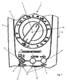
- the multimeter 1 has a housing 2, which is composed of two housing shells 3, 4.
- the upper housing shell 3 are designed as three sockets 5 input terminals 6 are provided, which serve for connecting measuring leads not shown.
- a measuring range switch 7 is provided, which is to be brought by rotation in one of the selected measured variables associated switching position.
- a mechanically acting locking device 8 is coupled, which allows blocking of the two outer input terminals 6 ', 6 "in such a way that the plug of a measuring line can only be inserted into a socket, which is set with the Meß Suitesschalter 7 measured variable equivalent.
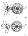
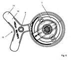
- the locking device 8 results in detail in particular from the Figures 2 - 6 , wherein the locking device 8 is shown together with the measuring range switch 7 from the inside of the housing forth in different switching positions.
- the locking device 8 is formed in the manner of a substantially mounted in its apex 9 pivotable angle lever 10, wherein the end portions 11 of the strip-like angle leg 12 can be brought by the measuring range switch 7 in a position to be closed with the input terminals 6 ', 6 "aligned position
- the angle lever 10 is arranged with the adjusting element 13 of the range switch 7 engageable switching projection 14, wherein the angle lever 10 is formed symmetrically with respect to the switching projection 14 and by the two legs 12 and the switching projection 14 is a tripartite star is formed in the drawing figures is clearly seen that the two angle legs 12 of the angle lever 10, the middle input terminal 6 '' 'overlap, so that it can not be closed by the end portions 11 of the angle leg 12.
- the switching projection 14 has a tip 16 which engages in a Mit predominantlyausEnglishung the rotary measuring range switch 7.
- a groove 18 is arranged in the region of the tip 16, which surrounds a driving projection 19 arranged in the recess 17 of the measuring range switch 7.
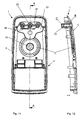
- the locking device 8 is arranged in a waterproof encapsulated socket housing 20, wherein the Socket housing 20 is formed by a side wall surrounding the locking device 8 laterally and a Buchsenarmewandung 22, on which are integrally formed with the input terminals aligned contact sleeve carrier.
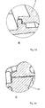
- the contacts of the sockets may be welded into the contact sleeve carriers, but there is also the possibility that the contacts on circumferential seals of the bushings with double undercut as well as in FIG. 14 is shown sealed.
- the contacts are shown as contact sleeves 23, which are arranged in sleeve-like contact sleeve carriers.
- the Buchsenarmewandung 22 is welded to the side wall 21 of the housing 20 ultrasonic and thus tightly connected.
- the angle lever 10 engages with a sleeve-like bearing element 35 a rotary bearing projection 36, wherein the rotary bearing element is mounted in a recess of the Buchsenarriwandung 22.
Landscapes
- Physics & Mathematics (AREA)
- General Physics & Mathematics (AREA)
- Measuring Instrument Details And Bridges, And Automatic Balancing Devices (AREA)
- Amplifiers (AREA)
- Gyroscopes (AREA)
- Details Of Connecting Devices For Male And Female Coupling (AREA)
Claims (14)
- Multimètre (1) pourvu d'un boîtier (2) comprenant au moins trois raccords d'entrée (6) qui sont réalisés sous la forme de fiches femelles (5), qui sont destinés au raccordement de deux conducteurs de mesure dont un au moins, lors du changement de la grandeur à mesurer qu'il s'agit de contrôler, doit être relié à un autre raccord d'entrée (6) associé à cette nouvelle grandeur à mesurer, et comprenant un sélecteur de gammes (7) qui doit être amené dans une position de commutation associée à la grandeur à mesurer choisie, sachant qu'est accouplé au sélecteur de gammes (7) un dispositif de blocage (8) à action mécanique qui permet un blocage de raccords d'entrée déterminés (6', 6") d'une manière telle qu'une mise en contact de réception d'un signal de mesure par l'intermédiaire des conducteurs de mesure ne peut avoir lieu à chaque fois que sur les raccords d'entrée auxquels est associée une grandeur à mesurer correspondant à la grandeur à mesurer qui a été réglée au moyen du sélecteur de gammes (7), sachant que le dispositif de blocage (8) est pourvu d'un apex (9) et d'un levier angulaire (10) rotatif assemblé sensiblement à l'apex, le levier angulaire comportant des ailes d'angle (12) en forme de bande comprenant des extrémités (11) et lesdites extrémités desdites ailes d'angle (12) en forme de bande peuvent être amenées par ledit sélecteur de gammes (7) dans une position qui couvre les raccords d'entrée (6', 6") à bloquer,
caractérisé en ce que
ledit dispositif de blocage (8) est disposé dans un boîtier de connexion (20), le boîtier de connexion ayant des parois latérales (21) qui entourent latéralement ledit dispositif de blocage (8) et une paroi de support de douilles (22), sachant que la paroi de support de douilles (22) est connectée étroitement à la paroi latérale (21) dudit boîtier (2). - Multimètre selon la revendication 1,
caractérisé en ce que
une saillie (14) est disposée sur ledit levier angulaire (10) pour s'engager avec un élément d'ajustement (13) disposé sur ledit sélecteur de gammes (7). - Multimètre selon la revendication 2,
caractérisé en ce que
ledit levier angulaire (10) a une forme symétrique relatif à ladite saillie (14) et une étoile à trois pointes est formée par les deux ailes d'angle (12) ainsi que ladite saillie (14). - Multimètre selon l'une des revendications 1 à 3,
caractérisé en ce que
les deux ailes d'angle (12) du levier angulaire (10) s'étendent à côté d'un raccord d'entrée central (6"'). - Multimètre selon la revendication 4,
caractérisé en ce que
l'ouverture dudit raccord d'entrée central (6"'), le point d'appui du levier angulaire (10) et le centre de rotation (15) dudit sélecteur de gammes (7) sont situés sur une droite. - Multimètre selon l'une des revendications 2 à 5,
caractérisé en ce que
ladite saillie (14) comporte une pointe (16) qui s'engage avec un creux d'entraînement (17) dudit sélecteur de gammes rotatif (7). - Multimètre selon la revendication 6,
caractérisé en ce que
ledit sélecteur de gammes (7) comporte une saillie d'entraînement (14) qui s'étend dans ledit creux d'entraînement (17) et une rainure (18) est disposée dans la région de la pointe (16), la rainure entourant ladite saillie d'entraînement (14). - Multimètre selon l'une des revendications précédentes,
caractérisé en ce que- des douilles de contact sont intégralement disposées dans ladite paroi de support de douilles (22),- la douille de contact est alignée avec lesdits raccords d'entrée (6),- des contacts des raccords d'entrée (6) sont soudés avec les douilles de contact. - Multimètre selon l'une des revendications précédentes,
caractérisé en ce que
ladite paroi de support de douilles (22) est soudée avec la paroi latérale (21) dudit boîtier (20). - Multimètre selon l'une des revendications précédentes,
caractérisé en ce que
lesdites extrémités (11) des ailes d'angle (12) peuvent être pivotées sur les côtés latéraux (30) du boîtier de connexion (20), les côtés latéraux étant disposés au-dessus desdits raccords d'entrée (6', 6") qui peuvent être bloqués par ledit dispositif de blocage (8). - Multimètre selon l'une des revendications précédentes,
caractérisé en ce que
des nervures de renforcement (32) sont disposées aux bords latéraux (31) dudit levier angulaire (10). - Multimètre selon l'une des revendications 2 à 11,
caractérisé en ce que
lesdites nervures de renforcement (32) des bords latéraux (31) dudit levier angulaire (10) se prolongent le long de bords latéraux (33) de ladite saillie (14). - Multimètre selon l'une des revendications précédentes,
caractérisé en ce que
ledit levier angulaire (10) entoure une saillie de palier rotatif (36) avec un élément de palier de type douille (35) et l'élément de palier rotatif étant monté dans un creux de la paroi de support de douilles (22). - Multimètre selon l'une des revendications 8 à 13,
caractérisé en ce que
lesdites douilles de contact (23) sont agencées en série et connectées l'une à l'autre par un dispositif de renforcement (40), ledit dispositif de renforcement étant disposé entre les douilles de contact et aligné avec ladite paroi de support de douilles (22).
Priority Applications (3)
| Application Number | Priority Date | Filing Date | Title |
|---|---|---|---|
| SI200630826T SI1801598T1 (sl) | 2005-12-23 | 2006-09-26 | Multimeter |
| PL06020080T PL1801598T3 (pl) | 2005-12-23 | 2006-09-26 | Miernik uniwersalny |
| CY20101101124T CY1110976T1 (el) | 2005-12-23 | 2010-12-06 | Πολυμετρο |
Applications Claiming Priority (1)
| Application Number | Priority Date | Filing Date | Title |
|---|---|---|---|
| DE102005062624A DE102005062624B8 (de) | 2005-12-23 | 2005-12-23 | Multimeter |
Publications (3)
| Publication Number | Publication Date |
|---|---|
| EP1801598A2 EP1801598A2 (fr) | 2007-06-27 |
| EP1801598A3 EP1801598A3 (fr) | 2008-06-04 |
| EP1801598B1 true EP1801598B1 (fr) | 2010-09-08 |
Family
ID=37820636
Family Applications (1)
| Application Number | Title | Priority Date | Filing Date |
|---|---|---|---|
| EP06020080A Active EP1801598B1 (fr) | 2005-12-23 | 2006-09-26 | Multimètre |
Country Status (10)
| Country | Link |
|---|---|
| US (1) | US7439725B2 (fr) |
| EP (1) | EP1801598B1 (fr) |
| AT (1) | ATE480780T1 (fr) |
| CY (1) | CY1110976T1 (fr) |
| DE (2) | DE102005062624B8 (fr) |
| DK (1) | DK1801598T3 (fr) |
| ES (1) | ES2352562T3 (fr) |
| PL (1) | PL1801598T3 (fr) |
| PT (1) | PT1801598E (fr) |
| SI (1) | SI1801598T1 (fr) |
Families Citing this family (4)
| Publication number | Priority date | Publication date | Assignee | Title |
|---|---|---|---|---|
| US8338710B2 (en) * | 2010-11-03 | 2012-12-25 | Ford Global Technologies, Llc | Short-preventing shield for wire harness terminals |
| JP5912919B2 (ja) * | 2012-06-28 | 2016-04-27 | 日置電機株式会社 | マルチメータ |
| DE102012022584B4 (de) * | 2012-11-20 | 2015-01-15 | Phoenix Contact Gmbh & Co. Kg | Funktionseinheit zur Messung des Isolationswiderstandes einer elektrischen Anlage |
| US9568504B2 (en) | 2013-03-15 | 2017-02-14 | Milwaukee Electric Tool Corporation | Digital multi-meter |
Family Cites Families (9)
| Publication number | Priority date | Publication date | Assignee | Title |
|---|---|---|---|---|
| JPH0626946B2 (ja) | 1985-08-14 | 1994-04-13 | 株式会社豊田自動織機製作所 | 自動変速機を備えた車両の走行判別方法 |
| JPH0411387Y2 (fr) * | 1985-08-28 | 1992-03-23 | ||
| US4951834A (en) * | 1989-09-12 | 1990-08-28 | John Fluke Mfg. Co., Inc. | Molded gasket for instrument housing |
| DE4027801C2 (de) * | 1990-09-01 | 1994-05-26 | Metrawatt Gmbh | Multimeter mit mindestens drei Eingangsanschlüssen |
| JPH04118669U (ja) * | 1991-04-05 | 1992-10-23 | 横河インスツルメンツ株式会社 | 測定器の入力保護機構 |
| JPH06239333A (ja) | 1993-02-16 | 1994-08-30 | Asahi Chem Ind Co Ltd | 牛乳容器 |
| KR950006889Y1 (ko) * | 1993-04-20 | 1995-08-22 | 엘지정밀 주식회사 | 디지탈 멀티메타의 입력 플러그 오삽입 방지 및 경보장치 |
| JP3156494B2 (ja) * | 1994-04-01 | 2001-04-16 | セイコーエプソン株式会社 | デジタルマルチメータ |
| JP3522030B2 (ja) * | 1995-01-19 | 2004-04-26 | セイコーエプソン株式会社 | 誤入力防止機構付きマルチメータ |
-
2005
- 2005-12-23 DE DE102005062624A patent/DE102005062624B8/de not_active Expired - Fee Related
-
2006
- 2006-09-26 AT AT06020080T patent/ATE480780T1/de active
- 2006-09-26 PL PL06020080T patent/PL1801598T3/pl unknown
- 2006-09-26 PT PT06020080T patent/PT1801598E/pt unknown
- 2006-09-26 ES ES06020080T patent/ES2352562T3/es active Active
- 2006-09-26 DK DK06020080.5T patent/DK1801598T3/da active
- 2006-09-26 SI SI200630826T patent/SI1801598T1/sl unknown
- 2006-09-26 DE DE502006007827T patent/DE502006007827D1/de active Active
- 2006-09-26 EP EP06020080A patent/EP1801598B1/fr active Active
- 2006-12-26 US US11/645,833 patent/US7439725B2/en active Active
-
2010
- 2010-12-06 CY CY20101101124T patent/CY1110976T1/el unknown
Also Published As
| Publication number | Publication date |
|---|---|
| US7439725B2 (en) | 2008-10-21 |
| DE502006007827D1 (de) | 2010-10-21 |
| DE102005062624B8 (de) | 2008-07-24 |
| ES2352562T3 (es) | 2011-02-21 |
| PT1801598E (pt) | 2010-12-13 |
| DK1801598T3 (da) | 2011-01-03 |
| DE102005062624B4 (de) | 2008-04-10 |
| DE102005062624A1 (de) | 2007-07-05 |
| CY1110976T1 (el) | 2015-06-11 |
| ATE480780T1 (de) | 2010-09-15 |
| PL1801598T3 (pl) | 2011-05-31 |
| EP1801598A3 (fr) | 2008-06-04 |
| US20070159158A1 (en) | 2007-07-12 |
| SI1801598T1 (sl) | 2011-02-28 |
| EP1801598A2 (fr) | 2007-06-27 |
Similar Documents
| Publication | Publication Date | Title |
|---|---|---|
| EP2208213B1 (fr) | Module de connexion et appareil de commutation comportant un module de connexion | |
| DE69400313T3 (de) | Verbinder für übertragungsleitung und zusammenbau desselben | |
| DE102008014179A1 (de) | Schaltbrücke und Baueinheit aus mindestens zwei elektrischen Reihenklemmen und einer Schaltbrücke | |
| DE4408985B4 (de) | Elektrische Einrichtung, insbesondere Reihenklemme, mit einer Klemme für eine Schnellverbindung | |
| DE102007038221B3 (de) | Elektrischer Steckverbinder mit hermaphroditischen Kontaktelementen | |
| DE4027801A1 (de) | Multimeter mit mindestens drei eingangsanschluessen | |
| DE3233255C2 (de) | Elektrische Anschlußklemme, insbesondere Schaltanlagen-Reihenklemme | |
| DE10334655A1 (de) | Steckverbindervorrichtung für Kleinservomotoren | |
| DE1765978B1 (de) | Schaltungsblock zum elektrischen verbinden mittels steck verbindungen von elektrischen schaltungselementen | |
| DE202009003650U1 (de) | Kupplungsanordnung | |
| EP1355378A1 (fr) | Contact perce-isolant à borne | |
| DE2507860A1 (de) | Mehrfachstecker | |
| DE10045714A1 (de) | Steckverbinder für zumindest einen Flachfolienleiter | |
| EP0757409B1 (fr) | Connecteur électrique | |
| DE102005062624B4 (de) | Multimeter | |
| DE4018978A1 (de) | Schiebeschalter | |
| DE19942921A1 (de) | Steckverbinder, insbesondere Winkelsteckverbinder | |
| DE2622054C3 (de) | Elektromagnetisches Schaltgerät | |
| DE19738749A1 (de) | Verbinder vom Hebel-Typ | |
| DE19717954A1 (de) | Elektrischer Kontakt | |
| DE2022319A1 (de) | Steckerverbindung in einem Verteilersystem fuer elektrischen Strom | |
| DE3332914C2 (de) | Anschlußklemme für Niederspannungsanlagen, insbesondere Schaltgeräte | |
| DE202006015898U1 (de) | Elektrische Klemmvorrichtung | |
| CH653181A5 (en) | Electrical connecting element | |
| DE19709198A1 (de) | Steckeranordnung mit einem Betätigungsschieber |
Legal Events
| Date | Code | Title | Description |
|---|---|---|---|
| PUAI | Public reference made under article 153(3) epc to a published international application that has entered the european phase |
Free format text: ORIGINAL CODE: 0009012 |
|
| AK | Designated contracting states |
Kind code of ref document: A2 Designated state(s): AT BE BG CH CY CZ DE DK EE ES FI FR GB GR HU IE IS IT LI LT LU LV MC NL PL PT RO SE SI SK TR |
|
| AX | Request for extension of the european patent |
Extension state: AL BA HR MK YU |
|
| PUAL | Search report despatched |
Free format text: ORIGINAL CODE: 0009013 |
|
| AK | Designated contracting states |
Kind code of ref document: A3 Designated state(s): AT BE BG CH CY CZ DE DK EE ES FI FR GB GR HU IE IS IT LI LT LU LV MC NL PL PT RO SE SI SK TR |
|
| AX | Request for extension of the european patent |
Extension state: AL BA HR MK RS |
|
| 17P | Request for examination filed |
Effective date: 20080821 |
|
| 17Q | First examination report despatched |
Effective date: 20080926 |
|
| AKX | Designation fees paid |
Designated state(s): AT BE BG CH CY CZ DE DK EE ES FI FR GB GR HU IE IS IT LI LT LU LV MC NL PL PT RO SE SI SK TR |
|
| GRAP | Despatch of communication of intention to grant a patent |
Free format text: ORIGINAL CODE: EPIDOSNIGR1 |
|
| RIC1 | Information provided on ipc code assigned before grant |
Ipc: G01R 1/04 20060101AFI20100303BHEP Ipc: G01R 15/00 20060101ALI20100303BHEP |
|
| GRAS | Grant fee paid |
Free format text: ORIGINAL CODE: EPIDOSNIGR3 |
|
| GRAA | (expected) grant |
Free format text: ORIGINAL CODE: 0009210 |
|
| AK | Designated contracting states |
Kind code of ref document: B1 Designated state(s): AT BE BG CH CY CZ DE DK EE ES FI FR GB GR HU IE IS IT LI LT LU LV MC NL PL PT RO SE SI SK TR |
|
| REG | Reference to a national code |
Ref country code: GB Ref legal event code: FG4D Free format text: NOT ENGLISH |
|
| REG | Reference to a national code |
Ref country code: CH Ref legal event code: EP |
|
| REG | Reference to a national code |
Ref country code: IE Ref legal event code: FG4D Free format text: LANGUAGE OF EP DOCUMENT: GERMAN |
|
| RAP2 | Party data changed (patent owner data changed or rights of a patent transferred) |
Owner name: METRAWATT INTERNATIONAL GMBH |
|
| REF | Corresponds to: |
Ref document number: 502006007827 Country of ref document: DE Date of ref document: 20101021 Kind code of ref document: P |
|
| REG | Reference to a national code |
Ref country code: RO Ref legal event code: EPE |
|
| REG | Reference to a national code |
Ref country code: PT Ref legal event code: SC4A Free format text: AVAILABILITY OF NATIONAL TRANSLATION Effective date: 20101203 |
|
| REG | Reference to a national code |
Ref country code: NL Ref legal event code: T3 |
|
| REG | Reference to a national code |
Ref country code: SE Ref legal event code: TRGR |
|
| REG | Reference to a national code |
Ref country code: DK Ref legal event code: T3 |
|
| REG | Reference to a national code |
Ref country code: ES Ref legal event code: FG2A Effective date: 20110209 |
|
| REG | Reference to a national code |
Ref country code: SK Ref legal event code: T3 Ref document number: E 8607 Country of ref document: SK |
|
| REG | Reference to a national code |
Ref country code: PL Ref legal event code: T3 |
|
| PLBE | No opposition filed within time limit |
Free format text: ORIGINAL CODE: 0009261 |
|
| STAA | Information on the status of an ep patent application or granted ep patent |
Free format text: STATUS: NO OPPOSITION FILED WITHIN TIME LIMIT |
|
| 26N | No opposition filed |
Effective date: 20110609 |
|
| REG | Reference to a national code |
Ref country code: DE Ref legal event code: R097 Ref document number: 502006007827 Country of ref document: DE Effective date: 20110609 |
|
| PGFP | Annual fee paid to national office [announced via postgrant information from national office to epo] |
Ref country code: DK Payment date: 20110926 Year of fee payment: 6 |
|
| PGFP | Annual fee paid to national office [announced via postgrant information from national office to epo] |
Ref country code: IS Payment date: 20110920 Year of fee payment: 6 |
|
| PG25 | Lapsed in a contracting state [announced via postgrant information from national office to epo] |
Ref country code: HU Free format text: LAPSE BECAUSE OF FAILURE TO SUBMIT A TRANSLATION OF THE DESCRIPTION OR TO PAY THE FEE WITHIN THE PRESCRIBED TIME-LIMIT Effective date: 20110309 Ref country code: BG Free format text: LAPSE BECAUSE OF FAILURE TO SUBMIT A TRANSLATION OF THE DESCRIPTION OR TO PAY THE FEE WITHIN THE PRESCRIBED TIME-LIMIT Effective date: 20100908 |
|
| PGFP | Annual fee paid to national office [announced via postgrant information from national office to epo] |
Ref country code: LU Payment date: 20120928 Year of fee payment: 7 Ref country code: FI Payment date: 20120927 Year of fee payment: 7 Ref country code: IE Payment date: 20120927 Year of fee payment: 7 Ref country code: MC Payment date: 20120925 Year of fee payment: 7 Ref country code: LT Payment date: 20120920 Year of fee payment: 7 Ref country code: EE Payment date: 20120924 Year of fee payment: 7 Ref country code: RO Payment date: 20120925 Year of fee payment: 7 |
|
| PGFP | Annual fee paid to national office [announced via postgrant information from national office to epo] |
Ref country code: PL Payment date: 20120920 Year of fee payment: 7 Ref country code: TR Payment date: 20120925 Year of fee payment: 7 Ref country code: SI Payment date: 20120920 Year of fee payment: 7 Ref country code: SK Payment date: 20120924 Year of fee payment: 7 Ref country code: LV Payment date: 20120921 Year of fee payment: 7 Ref country code: GR Payment date: 20120928 Year of fee payment: 7 |
|
| PGFP | Annual fee paid to national office [announced via postgrant information from national office to epo] |
Ref country code: ES Payment date: 20120924 Year of fee payment: 7 |
|
| PGFP | Annual fee paid to national office [announced via postgrant information from national office to epo] |
Ref country code: PT Payment date: 20120326 Year of fee payment: 7 Ref country code: CY Payment date: 20120925 Year of fee payment: 7 |
|
| PG25 | Lapsed in a contracting state [announced via postgrant information from national office to epo] |
Ref country code: BG Free format text: LAPSE BECAUSE OF FAILURE TO SUBMIT A TRANSLATION OF THE DESCRIPTION OR TO PAY THE FEE WITHIN THE PRESCRIBED TIME-LIMIT Effective date: 20101208 |
|
| REG | Reference to a national code |
Ref country code: PT Ref legal event code: MM4A Free format text: LAPSE DUE TO NON-PAYMENT OF FEES Effective date: 20140326 |
|
| REG | Reference to a national code |
Ref country code: LT Ref legal event code: MM4D Effective date: 20130926 |
|
| PG25 | Lapsed in a contracting state [announced via postgrant information from national office to epo] |
Ref country code: MC Free format text: LAPSE BECAUSE OF NON-PAYMENT OF DUE FEES Effective date: 20130930 Ref country code: IS Free format text: LAPSE BECAUSE OF FAILURE TO SUBMIT A TRANSLATION OF THE DESCRIPTION OR TO PAY THE FEE WITHIN THE PRESCRIBED TIME-LIMIT Effective date: 20140331 Ref country code: FI Free format text: LAPSE BECAUSE OF NON-PAYMENT OF DUE FEES Effective date: 20130926 Ref country code: RO Free format text: LAPSE BECAUSE OF NON-PAYMENT OF DUE FEES Effective date: 20130926 |
|
| REG | Reference to a national code |
Ref country code: DK Ref legal event code: EBP Effective date: 20130930 |
|
| REG | Reference to a national code |
Ref country code: GR Ref legal event code: ML Ref document number: 20100402887 Country of ref document: GR Effective date: 20140403 |
|
| PG25 | Lapsed in a contracting state [announced via postgrant information from national office to epo] |
Ref country code: CY Free format text: LAPSE BECAUSE OF NON-PAYMENT OF DUE FEES Effective date: 20130926 Ref country code: LV Free format text: LAPSE BECAUSE OF NON-PAYMENT OF DUE FEES Effective date: 20130926 |
|
| REG | Reference to a national code |
Ref country code: SK Ref legal event code: MM4A Ref document number: E 8607 Country of ref document: SK Effective date: 20130926 |
|
| REG | Reference to a national code |
Ref country code: EE Ref legal event code: MM4A Ref document number: E004972 Country of ref document: EE Effective date: 20130930 |
|
| PG25 | Lapsed in a contracting state [announced via postgrant information from national office to epo] |
Ref country code: PT Free format text: LAPSE BECAUSE OF NON-PAYMENT OF DUE FEES Effective date: 20140326 |
|
| REG | Reference to a national code |
Ref country code: IE Ref legal event code: MM4A |
|
| PG25 | Lapsed in a contracting state [announced via postgrant information from national office to epo] |
Ref country code: EE Free format text: LAPSE BECAUSE OF NON-PAYMENT OF DUE FEES Effective date: 20130930 Ref country code: LT Free format text: LAPSE BECAUSE OF NON-PAYMENT OF DUE FEES Effective date: 20130926 Ref country code: IE Free format text: LAPSE BECAUSE OF NON-PAYMENT OF DUE FEES Effective date: 20130926 |
|
| REG | Reference to a national code |
Ref country code: SI Ref legal event code: KO00 Effective date: 20140604 |
|
| PG25 | Lapsed in a contracting state [announced via postgrant information from national office to epo] |
Ref country code: SI Free format text: LAPSE BECAUSE OF NON-PAYMENT OF DUE FEES Effective date: 20130927 Ref country code: GR Free format text: LAPSE BECAUSE OF NON-PAYMENT OF DUE FEES Effective date: 20140403 Ref country code: SK Free format text: LAPSE BECAUSE OF NON-PAYMENT OF DUE FEES Effective date: 20130926 |
|
| REG | Reference to a national code |
Ref country code: ES Ref legal event code: FD2A Effective date: 20141007 |
|
| PG25 | Lapsed in a contracting state [announced via postgrant information from national office to epo] |
Ref country code: DK Free format text: LAPSE BECAUSE OF NON-PAYMENT OF DUE FEES Effective date: 20130930 |
|
| PG25 | Lapsed in a contracting state [announced via postgrant information from national office to epo] |
Ref country code: PL Free format text: LAPSE BECAUSE OF NON-PAYMENT OF DUE FEES Effective date: 20130926 |
|
| REG | Reference to a national code |
Ref country code: PL Ref legal event code: LAPE |
|
| PG25 | Lapsed in a contracting state [announced via postgrant information from national office to epo] |
Ref country code: ES Free format text: LAPSE BECAUSE OF NON-PAYMENT OF DUE FEES Effective date: 20130927 |
|
| PG25 | Lapsed in a contracting state [announced via postgrant information from national office to epo] |
Ref country code: LU Free format text: LAPSE BECAUSE OF NON-PAYMENT OF DUE FEES Effective date: 20130926 |
|
| PG25 | Lapsed in a contracting state [announced via postgrant information from national office to epo] |
Ref country code: TR Free format text: LAPSE BECAUSE OF NON-PAYMENT OF DUE FEES Effective date: 20130926 |
|
| REG | Reference to a national code |
Ref country code: GR Ref legal event code: EP Ref document number: 20100402887 Country of ref document: GR Effective date: 20110119 |
|
| REG | Reference to a national code |
Ref country code: FR Ref legal event code: PLFP Year of fee payment: 11 |
|
| REG | Reference to a national code |
Ref country code: FR Ref legal event code: PLFP Year of fee payment: 12 |
|
| REG | Reference to a national code |
Ref country code: FR Ref legal event code: PLFP Year of fee payment: 13 |
|
| PGFP | Annual fee paid to national office [announced via postgrant information from national office to epo] |
Ref country code: BE Payment date: 20190923 Year of fee payment: 14 |
|
| REG | Reference to a national code |
Ref country code: BE Ref legal event code: MM Effective date: 20200930 |
|
| PG25 | Lapsed in a contracting state [announced via postgrant information from national office to epo] |
Ref country code: BE Free format text: LAPSE BECAUSE OF NON-PAYMENT OF DUE FEES Effective date: 20200930 |
|
| P01 | Opt-out of the competence of the unified patent court (upc) registered |
Effective date: 20230601 |
|
| PGFP | Annual fee paid to national office [announced via postgrant information from national office to epo] |
Ref country code: NL Payment date: 20230920 Year of fee payment: 18 Ref country code: GB Payment date: 20230921 Year of fee payment: 18 Ref country code: CZ Payment date: 20230913 Year of fee payment: 18 |
|
| PGFP | Annual fee paid to national office [announced via postgrant information from national office to epo] |
Ref country code: SE Payment date: 20230921 Year of fee payment: 18 Ref country code: FR Payment date: 20230919 Year of fee payment: 18 |
|
| PGFP | Annual fee paid to national office [announced via postgrant information from national office to epo] |
Ref country code: IT Payment date: 20230929 Year of fee payment: 18 |
|
| PG25 | Lapsed in a contracting state [announced via postgrant information from national office to epo] |
Ref country code: CZ Free format text: LAPSE BECAUSE OF NON-PAYMENT OF DUE FEES Effective date: 20240926 |
|
| REG | Reference to a national code |
Ref country code: SE Ref legal event code: EUG |
|
| REG | Reference to a national code |
Ref country code: NL Ref legal event code: MM Effective date: 20241001 |
|
| GBPC | Gb: european patent ceased through non-payment of renewal fee |
Effective date: 20240926 |
|
| REG | Reference to a national code |
Ref country code: DE Ref legal event code: R081 Ref document number: 502006007827 Country of ref document: DE Owner name: GOSSEN METRAWATT GMBH, DE Free format text: FORMER OWNER: METRAWATT INTERNATIONAL GMBH, 90449 NUERNBERG, DE |
|
| PG25 | Lapsed in a contracting state [announced via postgrant information from national office to epo] |
Ref country code: NL Free format text: LAPSE BECAUSE OF NON-PAYMENT OF DUE FEES Effective date: 20241001 |
|
| PG25 | Lapsed in a contracting state [announced via postgrant information from national office to epo] |
Ref country code: GB Free format text: LAPSE BECAUSE OF NON-PAYMENT OF DUE FEES Effective date: 20240926 |
|
| PG25 | Lapsed in a contracting state [announced via postgrant information from national office to epo] |
Ref country code: IT Free format text: LAPSE BECAUSE OF NON-PAYMENT OF DUE FEES Effective date: 20240926 |
|
| PG25 | Lapsed in a contracting state [announced via postgrant information from national office to epo] |
Ref country code: FR Free format text: LAPSE BECAUSE OF NON-PAYMENT OF DUE FEES Effective date: 20240930 |
|
| REG | Reference to a national code |
Ref country code: CH Ref legal event code: U11 Free format text: ST27 STATUS EVENT CODE: U-0-0-U10-U11 (AS PROVIDED BY THE NATIONAL OFFICE) Effective date: 20251001 |
|
| PGFP | Annual fee paid to national office [announced via postgrant information from national office to epo] |
Ref country code: DE Payment date: 20250917 Year of fee payment: 20 |
|
| PG25 | Lapsed in a contracting state [announced via postgrant information from national office to epo] |
Ref country code: SE Free format text: LAPSE BECAUSE OF NON-PAYMENT OF DUE FEES Effective date: 20240927 |
|
| PGFP | Annual fee paid to national office [announced via postgrant information from national office to epo] |
Ref country code: AT Payment date: 20250918 Year of fee payment: 20 |
|
| PGFP | Annual fee paid to national office [announced via postgrant information from national office to epo] |
Ref country code: CH Payment date: 20251001 Year of fee payment: 20 |