EP1801615A1 - Dispositif de capture d'image radiologique déclenché à distance - Google Patents
Dispositif de capture d'image radiologique déclenché à distance Download PDFInfo
- Publication number
- EP1801615A1 EP1801615A1 EP06026772A EP06026772A EP1801615A1 EP 1801615 A1 EP1801615 A1 EP 1801615A1 EP 06026772 A EP06026772 A EP 06026772A EP 06026772 A EP06026772 A EP 06026772A EP 1801615 A1 EP1801615 A1 EP 1801615A1
- Authority
- EP
- European Patent Office
- Prior art keywords
- light
- ray
- photons
- image
- screen
- Prior art date
- Legal status (The legal status is an assumption and is not a legal conclusion. Google has not performed a legal analysis and makes no representation as to the accuracy of the status listed.)
- Withdrawn
Links
- 230000001960 triggered effect Effects 0.000 title claims description 17
- 238000000034 method Methods 0.000 claims abstract description 35
- 238000004891 communication Methods 0.000 claims description 5
- 238000001514 detection method Methods 0.000 claims description 5
- OYPRJOBELJOOCE-UHFFFAOYSA-N Calcium Chemical compound [Ca] OYPRJOBELJOOCE-UHFFFAOYSA-N 0.000 claims description 4
- 229910052791 calcium Inorganic materials 0.000 claims description 4
- 239000011575 calcium Substances 0.000 claims description 4
- 238000012546 transfer Methods 0.000 claims description 4
- PBYZMCDFOULPGH-UHFFFAOYSA-N tungstate Chemical compound [O-][W]([O-])(=O)=O PBYZMCDFOULPGH-UHFFFAOYSA-N 0.000 claims description 4
- 229910052761 rare earth metal Inorganic materials 0.000 claims description 3
- 150000002910 rare earth metals Chemical class 0.000 claims description 3
- 230000005251 gamma ray Effects 0.000 claims description 2
- 230000008569 process Effects 0.000 abstract description 23
- 238000003384 imaging method Methods 0.000 description 10
- 238000005516 engineering process Methods 0.000 description 8
- OAICVXFJPJFONN-UHFFFAOYSA-N Phosphorus Chemical compound [P] OAICVXFJPJFONN-UHFFFAOYSA-N 0.000 description 7
- 239000013078 crystal Substances 0.000 description 7
- 238000010586 diagram Methods 0.000 description 7
- 238000012545 processing Methods 0.000 description 7
- 238000002601 radiography Methods 0.000 description 7
- 230000003287 optical effect Effects 0.000 description 6
- 239000000463 material Substances 0.000 description 4
- 230000005055 memory storage Effects 0.000 description 3
- 230000006855 networking Effects 0.000 description 3
- 239000000126 substance Substances 0.000 description 3
- 230000002093 peripheral effect Effects 0.000 description 2
- 230000005855 radiation Effects 0.000 description 2
- 238000009877 rendering Methods 0.000 description 2
- 229920000049 Carbon (fiber) Polymers 0.000 description 1
- 229910000831 Steel Inorganic materials 0.000 description 1
- MCVAAHQLXUXWLC-UHFFFAOYSA-N [O-2].[O-2].[S-2].[Gd+3].[Gd+3] Chemical compound [O-2].[O-2].[S-2].[Gd+3].[Gd+3] MCVAAHQLXUXWLC-UHFFFAOYSA-N 0.000 description 1
- 238000010521 absorption reaction Methods 0.000 description 1
- 230000004913 activation Effects 0.000 description 1
- 229910052782 aluminium Inorganic materials 0.000 description 1
- XAGFODPZIPBFFR-UHFFFAOYSA-N aluminium Chemical compound [Al] XAGFODPZIPBFFR-UHFFFAOYSA-N 0.000 description 1
- 238000005452 bending Methods 0.000 description 1
- XQPRBTXUXXVTKB-UHFFFAOYSA-M caesium iodide Chemical compound [I-].[Cs+] XQPRBTXUXXVTKB-UHFFFAOYSA-M 0.000 description 1
- 239000004917 carbon fiber Substances 0.000 description 1
- 230000000295 complement effect Effects 0.000 description 1
- 230000001066 destructive effect Effects 0.000 description 1
- 239000003814 drug Substances 0.000 description 1
- 230000005670 electromagnetic radiation Effects 0.000 description 1
- 230000006870 function Effects 0.000 description 1
- 239000004615 ingredient Substances 0.000 description 1
- 229910017053 inorganic salt Inorganic materials 0.000 description 1
- 238000009434 installation Methods 0.000 description 1
- 238000012423 maintenance Methods 0.000 description 1
- 230000007246 mechanism Effects 0.000 description 1
- 229910052751 metal Inorganic materials 0.000 description 1
- 239000002184 metal Substances 0.000 description 1
- 229910044991 metal oxide Inorganic materials 0.000 description 1
- 150000004706 metal oxides Chemical class 0.000 description 1
- VNWKTOKETHGBQD-UHFFFAOYSA-N methane Chemical compound C VNWKTOKETHGBQD-UHFFFAOYSA-N 0.000 description 1
- 238000012986 modification Methods 0.000 description 1
- 230000004048 modification Effects 0.000 description 1
- 230000001473 noxious effect Effects 0.000 description 1
- 238000009420 retrofitting Methods 0.000 description 1
- 150000003839 salts Chemical class 0.000 description 1
- 239000004065 semiconductor Substances 0.000 description 1
- 239000010959 steel Substances 0.000 description 1
- 230000007704 transition Effects 0.000 description 1
- 238000002211 ultraviolet spectrum Methods 0.000 description 1
- 238000007794 visualization technique Methods 0.000 description 1
Images



Classifications
-
- G—PHYSICS
- G01—MEASURING; TESTING
- G01T—MEASUREMENT OF NUCLEAR OR X-RADIATION
- G01T1/00—Measuring X-radiation, gamma radiation, corpuscular radiation, or cosmic radiation
- G01T1/16—Measuring radiation intensity
- G01T1/20—Measuring radiation intensity with scintillation detectors
- G01T1/2006—Measuring radiation intensity with scintillation detectors using a combination of a scintillator and photodetector which measures the means radiation intensity
-
- H—ELECTRICITY
- H04—ELECTRIC COMMUNICATION TECHNIQUE
- H04N—PICTORIAL COMMUNICATION, e.g. TELEVISION
- H04N23/00—Cameras or camera modules comprising electronic image sensors; Control thereof
- H04N23/30—Cameras or camera modules comprising electronic image sensors; Control thereof for generating image signals from X-rays
Definitions
- X-ray images can be taken with film in traditional radiography, they can be digitally generated using imaging plates in a process called computed radiography, and digital images can be generated directly from the X-rays themselves in a process called direct digital radiography.
- computed radiography a process called computed radiography
- digital images can be generated directly from the X-rays themselves in a process called direct digital radiography.
- Each of these systems has its drawbacks.
- film When film is used to process X-rays, the film must be purchased for each X-ray, and the film must be developed in a process that takes somewhere around 90 seconds to 5 minutes per shot. A patient must wait for the entire developing time to determine if an image is clear or if a retake is needed.
- processing the films requires that noxious chemicals be used and stored, and disposed.
- Computed radiography removes the film from the X-ray process, replacing it instead with a digital imaging plate the same dimensions as the film and placed in the same location. After the imaging plate is exposed to the X-rays, it is placed in an imaging reader, which takes about 90 seconds to generate the digital image. This delay, while not insurmountable when human adults are having their X-rays taken is much more problematic when the X-ray subject is a small child or an animal which does not understand the need to remain quiet and positioned. Furthermore, the imaging plate is expensive and fragile, an expensive imaging reader must also be used, and generating the digital X-ray image takes roughly the same time as in conventional radiography.
- Direct digital radiography uses an imaging sensor in the path of the X-rays to take a direct digital X-ray, which can then immediately be displayed on a computer screen, and saved in a digital file for easy reference.
- it is difficult to adequately shield the imaging sensor from the X-rays requiring that this expensive piece of equipment be regularly replaced.
- a system for capturing X-ray images comprises a screen for converting X-ray photons to light photons when an X-ray source sends X-ray photons to the screen; a light-measuring device that records at least some of the light photons to produce an image; a photon detection device which triggers the light-measuring device when it detects photons over a threshold value. Furthermore, there is no electronic link between the circuitry of the X-ray source and the system for capturing X-ray images.
- a method of creating X-ray images comprises converting at least some X-ray photons generated from an X-ray source to light photons; and then, using a mirror to reflect light such that a camera placed outside of the direct path of the X-rays can take a picture of substantially all of the X-ray image.
- a sensor detects photons in greater than a threshold amount, the light image sensor is triggered which, in turn, triggers the camera to take the picture of the X-ray image.
- a system to display an X-ray image comprises a screen that converts at least a portion of X-ray photons generated by an X-ray source into light photons; and a mirror that reflects the light path of a camera out of the direct path of the X-rays such that the camera is substantially focused on the screen which converts at least a portion of the X-ray photons into light photons.
- the camera converts at least a portion of the light photons to a digital X-ray image.
- essentially all of the X-ray photons in the direct path of the camera are absorbed by a shield, and so do not strike the camera.
- the system also comprises a computer with a screen used to display a representation of the digital X-ray image.
- the present application relates to technologies for remote-triggered X-ray devices. Described embodiments implement one or more of the described technologies.
- the various technologies can be used in combination or independently. Different embodiments implement one or more of the described technologies. Some technologies described herein can be used in conjunction with a computer; such a computer could be a desktop computer, a portable computer, a handheld computer, a wearable computing device, a Personal Digital Assistant (PDA), or an intelligent cell phone.
- a computer such as a computer could be a desktop computer, a portable computer, a handheld computer, a wearable computing device, a Personal Digital Assistant (PDA), or an intelligent cell phone.
- PDA Personal Digital Assistant
- X-rays 105 are electromagnetic radiation with a wavelength between 10 nanometers and 100 picometers. This corresponds to frequencies between 30 PHz and 3 EHz. X-ray wavelengths overlap those of Gamma rays; Gamma rays are generated by transitions within the atomic nucleus, while X-rays are generated by energetic electron processes. For the purposes of these embodiments, all radiation with wavelengths between 10 nanometers and 100 picometers, no matter what the source, should be considered X-rays.
- the screen 110 transforms X-rays 105 into light 115, which may be fluorescent light. In some embodiments, the light may be in the visible, the infrared, or the ultraviolet spectrum, or some combination thereof.
- These screens sometimes called intensifying screens, generally contain, among other ingredients, a layer of phosphor crystals. When an X-ray photon strikes a phosphor crystal, many light photons are emitted, which will then be photographed to create the X-ray image.
- Two major types of phosphors used to create intensifying screens for use with envisioned embodiments are calcium tungstate (CaWO 4 ) and various rare earths.
- Gadolinium Oxysulfide and Thallium-doped Cesium Iodide are among the substances suitable for building an intensifying screen.
- other substances that convert X-rays to light such as metal screens, are also envisioned to be used.
- the screen 110, 205 is mounted on the top of the beam enclosure unit 120.
- This beam enclosure unit 120 in an exemplary embodiment, is installed under a table top.
- a variety of mounting devices adapted to each type of table manufactured are expected to be used in the installation. When an embodiment is used in a veterinary setting, those mounting in common use in veterinary medicine are used.
- the beam enclosure unit 120 should be installed such that the system weight is supported and such that an X-ray beam is appropriately aligned during exposure.
- the support mechanism can allow freedom of motion when an X-ray support tower (not shown) is moved toward either end of the table that the beam enclosure unit 120 is installed underneath.
- the beam enclosure unit 120 is installed without a table present.
- the aperture of the beam enclosure unit 120 through which the X-rays 105 enter measures, in exemplary embodiments, either 14" x 14" or, 14" x 17".
- a light-tight cover is also included (not shown) which also may act as support for the screen 110.
- the screen 110 may be bonded to the light-tight cover.
- the light-tight cover may be made of carbon fiber to minimize X-ray absorption.
- the light-tight cover can be bolted around its perimeter to the beam enclosure 120 with tamper-proof screws.
- the light 115 is captured by the accumulator 220, which, in an exemplary embodiment, is designed to minimize quantum efficiency loss and provide an optically flat field. A small amount of adjustment of the light rays entering the accumulator 220 may be provided by the accumulator 220.
- a light measuring device such as a camera 230 is placed in an enclosure 215 just behind the accumulator 220.
- Shielding 210 protects the camera 230 from the X-rays 105. Because of the location of the shielding 210 in relation to the X-rays 105 in the beam enclosure unit 120, steel can be used for the shielding rather than the more common lead, as the camera 230 is out of the direct path of the X-rays. In another exemplary embodiment, lead is used for the shielding. Additional shielding may be placed along other areas where X-rays may penetrate 225, 235. The dangers of X-ray radiation on living tissue is well-known. X-rays are also destructive of sensitive equipment.
- X-ray exposure can greatly shorten the working life of a camera used to take an X-ray.
- Shielding the camera 230, as is done here, both by using traditional shielding 210, 225, 235, and by placing the camera 230out of the direct path of the X-rays, can lead to a much longer camera life, and can greatly reduce the amount of maintenance needed on the X-ray device.
- a mirror 240 is also included as part of the beam enclosure 120, in an exemplary embodiment.
- An accumulator 220 is arranged in front of the camera 230.
- the mirror 240 reflects the light 115 seen by the camera 230 at an angle that focuses the light 115 across the length of the screen 110.
- the reflected light path is shown at 310, 315. It can be seen that the entire aperture of the beam enclosure unit 120 through which the X-rays 105 enter can effectively be "seen" by the camera 230 through the image reflected in the mirror 240. Thus, when the camera 230 is triggered, the camera 230 captures substantially the entire X-ray image (as translated into light).
- the mirror 240 in an exemplary embodiment, is mounted at a 45-degree angle, though other angles of mounting are envisioned. Additionally, the mirror 240 may be enhanced by surface preparation to provide additional light reflection when mounted between 43 degrees and 47 degrees to the incident light beam. The mirror 240 may reflect in excess of 97.5 degrees of the available light, and may be aluminum-enhanced, and micro- or pico-ground.
- the X-ray source 100 shown in FIGs. 1A and 1B and the remote-triggered X-ray device.
- This allows the X-ray device to be easily retrofitted to existing X-ray sources, as there is no need for an electrical connection between the existing X-ray source and this device. Therefore, wiring diagrams need not be consulted, for example. This allows existing X-ray sources, whose wiring may have been lost, to still be retrofitted with minimum difficulty. In systems whose wiring is known, the expense and time of wiring the two devices together is eliminated. Further, an entire category of timing problems between the systems is also eliminated.
- a photon detector 320 is provided which triggers substantially at the exact moment that the visible light rays 115 are available to be captured by the camera 230.
- the location of the photon detector 320 in FIG. 3 is for illustrative purposes only; it can be placed anywhere within the beam enclosure unit 120 that is convenient. It may also be placed outside the beam enclosure unit 120 if by such placement it can still trigger the camera 230 at the time of X-ray generation without being integrated into the circuitry of the host X-ray source.
- the camera 230 When the camera 230 is triggered by the photon detector 320, it creates a digital image representative of the X-rays. As shown in FIG. 1B, this digital image can then be transferred through a link 125 to a computer 130, which then processes the image and displays it on a computer screen 135.
- the system is used primarily in a veterinary setting.
- FIG. 4 a block diagram of a system for capturing X-ray images 400 shows an exemplary embodiment of the systems discussed herein.
- the system for capturing X-ray images 400 consists of a screen 402, which converts X-ray photons to light photons.
- the screen contains a material, among other components, which, when struck by an X-ray photon, generates light photons.
- Inorganic salts also known as phosphors, are among the materials that are suitable to generate light photons when struck by an X-ray photon. If an inorganic salt is used, it will generate florescent light. Only a portion of the X-rays will be absorbed by the screen, causing light photons to be emitted.
- the system also contains a mirror 406.
- the light rays generated by the screen 402 continue on the same path as that of the initial X-rays that generated the light.
- the mirror 406 reflects the light rays that strike it at such an angle that the light-measuring device 408 is focused on the screen 402 such that when the light-measuring device 408 is triggered, a view of substantially the entire screen is captured.
- the image path from the light measuring device 408 is folded, such that the light rays strike the mirror 406 and are bent such that at least some of the light rays cross paths on their way to the screen.
- the illustrated embodiment shows the rays bending once; other embodiments can employ image paths that bend the rays multiple times.
- the mirror 406 is placed at a 45 degree angle to the screen 402. In alternate embodiments, the mirror is positioned such that a portion of the screen 402 is captured.
- an accumulator 404 is used to at least partially focus the light on the light-measuring device 408.
- This light-measuring device 408, in an exemplary embodiment, is a charge-coupled device 409.
- a complementary metal oxide semiconductor (CMOS) device 410 is used as the light-measuring device 408.
- CMOS complementary metal oxide semiconductor
- An exemplary embodiment employs more than one light-measuring device.
- each pixel that makes up a light-measuring array in either the charge-coupled device 409 or the CMOS device 410 is struck by some number of light photons, which are then converted to electrons. The number of electrons in each pixel is considered the pixel's charge.
- a converter 412 then converts the charge into a digital value. Each of the digital values is then associated with a specific gray-scale value, in an exemplary embodiment to form a detailed black and white image.
- the light-measuring device 408 records the images in color, with each digital value is associated with a color, using some color space to assign specific values to the pixels.
- Examples of exemplary color spaces known to those in the art that could be used in exemplary embodiments are RGB, CNY, CMYK, HSV, HLS, and so on.
- a large-format charge-coupled device has an 11 megapixel grid, which provides up to 16 bits of grey depth in each pixel, resulting in over 65,000 shades of gray being converted into the eventual image.
- a 4 megapixel grid is used, which provides two line pairs per millimeter resolution on the final image.
- the system itself must determine when to trigger the light-measuring device 408. It does this using a photon detection device 414, which, when it registers either X-rays or light, sends an activation message to the light-measuring device 408 telling it to "snap the picture.” Some embodiments may only trigger the light-measuring device 408 when a number of photons over a background threshold amount are detected. If X-rays are detected, an exemplary embodiment uses an ionization chamber as the photon detection device 414. In some embodiments, a gamma ray detector is used for the photon-detector device.
- the digital image in the converter 412 which represents an X-ray of a subject, is transferred to a computer 418 using a link 416.
- This link may be a network connection. If so, it may be a wireless network connection.
- the computer 418 processes it to make it clear and readable on a computer screen, and then displays it on a computer screen 420.
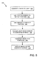
- FIG. 5 is an operational flow diagram illustrating a process for creating X-ray images 500.
- the process begins at process block 502, where X-rays are converted into light.
- the phosphor crystal absorbs the X-ray and emits a number of light photons.
- the size of the phosphor layer and the size of the individual phosphor crystals are some of the factors that determine the level of detail in the eventual X-ray image. The larger the individual crystal and the thicker the phosphor layer, the more spread-out the individual light photons are that are generated by the crystal.
- the image detail is degraded by the size of the light spread, as the same amount of information is smeared over a larger area.
- a photon sensor is used to detect whether X-rays or light rays are present.
- a mirror is used to reflect the light used by a light-measuring device such that essentially all of the light converted by X-rays can be "seen” by the light-measuring device, even if the light-measuring device is out of the direct path of the X-rays.
- the process 500 is independent from an X-ray source process which creates the X-rays, so a method internal to process 500 must be used to determine when an X-ray machine has taken an X-ray.
- a light-image sensor is triggered which generates an image corresponding to the X-ray.
- this light image sensor may be a charge-coupled device, a CMOS device, or another device suitable for translating light energy into digital output.
- the image is transferred to a computer.
- the transfer may take place through a network connection.
- the network may be local or wide-area network.
- the network may be wired or the image may travel using a wireless network.
- the image is sent through a wireless connection to a communication device, such as a laptop or a portable communication device such as a PDA or an internet-enabled cell phone.
- the image after it has been processed by the computer, is displayed on a computer screen.
- the processing comprises turning the digital representation into an image that can be viewed on a screen, and may comprise certain modifications to the image, as are known to those of skill in the art. For example, if the image was initially exposed for too long and is too dark, an algorithm may be employed which "lightens" the image, making it easier to read. In some embodiments, an algorithm may be employed on some images to sharpen specific areas, increasing contrast over what would otherwise be seen. A variety of other visualization techniques may be used as well, such as thick-slab rendering, shaded volume rendering, shaded surface display, multi-planar reformatting, flexible clipping, maximum intensity projection, perspective viewing, and the like.
- Processing may be provided which allows the image to be transferred to a different system, or which stores the image in a standard format, such as DICOM, CMP, PNG, JPEG, TIFF, GIF, or other widely-available format.
- a standard format such as DICOM, CMP, PNG, JPEG, TIFF, GIF, or other widely-available format.
- Some embodiments may include algorithms which store the images in a proprietary format, the proprietary format being a format used by a single vendor or a limited number of vendors.
- Other processing as known to those of skill in the art, is also envisioned
- an exemplary system for implementing at least portions of the disclosed technology includes a general purpose computing device in the form of a conventional computer 600, which may be a PC, or a larger system, including a processing unit 602, a system memory 604, and a system bus 606 that couples various system components including the system memory 604 to the processing unit 602.
- the system bus 606 may be any of several types of bus structures, including a memory bus or memory controller, a peripheral bus, and a local bus using any of a variety of bus architectures.
- the system memory 604 includes read only memory (ROM) 608 and random access memory (RAM) 610.
- a basic input/output system (BIOS) 612 containing the basic routines that help with the transfer of information between elements within the computer 600, is stored in ROM 608.
- the computer 600 further includes one or more of a hard disk drive 614 for reading from and writing to a hard disk (not shown), a magnetic disk drive 616 for reading from or writing to a removable magnetic disk 617, and an optical disk drive 618 for reading from or writing to a removable optical disk 619 (such as a CD-ROM or other optical media). Flash memory (not shown) may also be used to store information. These disks 614, 616, 617, 618, and 619, the hard drive and the flash memory may be used separately or in combination to store digital X-ray images. Furthermore a cataloging system may also be included to allow easy retrieval of a desired image.
- the hard disk drive 614, magnetic disk drive 616, and optical disk drive 618 are connected to the system bus 606 by a hard disk drive interface 620, a magnetic disk drive interface 622, and an optical drive interface 624, respectively.
- the drives and their associated computer-readable media provide nonvolatile storage of computer-readable instructions, data structures, program modules, and other data for the computer 600. They may also be used to store algorithms used to process, store, and retrieve the digital images, as well as other algorithms used in conjunction with the digital X-ray images.
- Computer-readable media which can store data that is accessible by a computer, such as magnetic cassettes, flash memory cards, digital video disks, CDs, DVDs, RAMs, ROMs, and the like (none of which are shown), may also be used in the exemplary operating environment.
- a number of program modules may be stored on the hard disk 614, magnetic disk 617, optical disk 619, ROM 608, or RAM 610, including an operating system 630, one or more application programs 632, including applications to manipulate, store, transfer, etc. the digital X-ray images, other program modules 634, and program data 636.
- a user may enter commands and information into the computer 600 through input devices, such as a keyboard 640 and pointing device 642 (such as a mouse).
- Other input devices may include a digital camera, microphone, joystick, game pad, satellite dish, scanner, or the like (also not shown).
- serial port interface 644 that is coupled to the system bus 606, but may be connected by other interfaces, such as a parallel port, game port, or universal serial bus (USB) (none of which are shown).
- a monitor 646 or other type of display device is also connected to the system bus 606 via an interface, such as a video adapter 648. This monitor 646 may be used to display the digital X-ray images.
- Other peripheral output devices such as speakers and printers (not shown), may be included.
- the computer 600 may operate in a networked environment using logical connections to one or more remote computers 650, and to a remote-triggered X-ray imaging system as shown, for example, in FIG. 1.
- the remote computer 650 may be another computer, a server, a router, a network PC, or a peer device or other common network node, and typically includes many or all of the elements described above relative to the computer 600, although only a memory storage device 652 has been illustrated in FIG. 6.
- the logical connections depicted in FIG. 6 include a local area network (LAN) 654 and a wide area network (WAN) 656.
- LAN local area network
- WAN wide area network
- the computer 600 When used in a LAN networking environment, the computer 600 is connected to the LAN 654 through a network interface 658. When used in a WAN networking environment, the computer 600 typically includes a modem 660 or other means for establishing communications over the WAN 656, such as the Internet.
- the modem 660 which may be internal or external, is connected to the system bus 606 via the serial port interface 644.
- program modules depicted relative to the computer 600, or portions thereof may be stored in the remote memory storage device 652.
- Digital X-ray images may also be stored in the remote memory storage device 652.
- the network connections shown are exemplary, and other means of establishing a communications link between the computers may be used.
Landscapes
- Engineering & Computer Science (AREA)
- Multimedia (AREA)
- Signal Processing (AREA)
- Physics & Mathematics (AREA)
- Health & Medical Sciences (AREA)
- Life Sciences & Earth Sciences (AREA)
- General Physics & Mathematics (AREA)
- High Energy & Nuclear Physics (AREA)
- Molecular Biology (AREA)
- Spectroscopy & Molecular Physics (AREA)
- Measurement Of Radiation (AREA)
- Analysing Materials By The Use Of Radiation (AREA)
Applications Claiming Priority (1)
| Application Number | Priority Date | Filing Date | Title |
|---|---|---|---|
| US11/317,462 US20070145282A1 (en) | 2005-12-22 | 2005-12-22 | Remote triggered X-ray image capture device |
Publications (1)
| Publication Number | Publication Date |
|---|---|
| EP1801615A1 true EP1801615A1 (fr) | 2007-06-27 |
Family
ID=37876834
Family Applications (1)
| Application Number | Title | Priority Date | Filing Date |
|---|---|---|---|
| EP06026772A Withdrawn EP1801615A1 (fr) | 2005-12-22 | 2006-12-22 | Dispositif de capture d'image radiologique déclenché à distance |
Country Status (2)
| Country | Link |
|---|---|
| US (1) | US20070145282A1 (fr) |
| EP (1) | EP1801615A1 (fr) |
Cited By (1)
| Publication number | Priority date | Publication date | Assignee | Title |
|---|---|---|---|---|
| CN101868181A (zh) * | 2007-11-20 | 2010-10-20 | 卡尔斯特里姆保健公司 | 用于改进数字x射线检测器的点火延迟 |
Families Citing this family (9)
| Publication number | Priority date | Publication date | Assignee | Title |
|---|---|---|---|---|
| US20070257197A1 (en) * | 2006-05-02 | 2007-11-08 | General Electric Company | Detector assembly and inspection system |
| US7463716B2 (en) * | 2006-08-04 | 2008-12-09 | X-Scan Imaging Corporation | Linear X-ray detector using rod lens array |
| EP2031379A1 (fr) * | 2007-07-16 | 2009-03-04 | General Electric Company | Ensemble de détection et système d'inspection |
| AU2009322647A1 (en) * | 2008-12-01 | 2011-07-07 | Life Image Inc. | Medical imaging viewer |
| US8130904B2 (en) | 2009-01-29 | 2012-03-06 | The Invention Science Fund I, Llc | Diagnostic delivery service |
| US8116429B2 (en) | 2009-01-29 | 2012-02-14 | The Invention Science Fund I, Llc | Diagnostic delivery service |
| US8369483B2 (en) | 2010-09-07 | 2013-02-05 | William Eugene Campbell | Multi-resolution X-ray image capture |
| BE1020625A4 (nl) * | 2012-04-23 | 2014-02-04 | Agfa Healthcare | Werkwijze voor het bepalen van de standaard instelwaarde voor de vertragingstijd van een radiografische generator. |
| KR20140000477A (ko) | 2012-06-22 | 2014-01-03 | 삼성디스플레이 주식회사 | 엑스레이 검출기, 엑스레이 검출기를 포함하는 엑스레이 촬영 시스템 및 엑스레이 검출기 구동 방법 |
Citations (2)
| Publication number | Priority date | Publication date | Assignee | Title |
|---|---|---|---|---|
| US5309496A (en) * | 1992-12-23 | 1994-05-03 | Winsor Robin W | Filmless X-ray apparatus and method of using the same |
| US6339633B1 (en) * | 1998-11-27 | 2002-01-15 | Wuestec Medical, Inc. | Automatic exposure initiation in a digital CCD camera x-ray imager |
Family Cites Families (11)
| Publication number | Priority date | Publication date | Assignee | Title |
|---|---|---|---|---|
| US4873708A (en) * | 1987-05-11 | 1989-10-10 | General Electric Company | Digital radiographic imaging system and method therefor |
| US5127032A (en) * | 1987-12-03 | 1992-06-30 | Johns Hopkins University | Multi-directional x-ray imager |
| FI941589A7 (fi) * | 1994-04-07 | 1996-01-12 | Stig Svensson | Laite röntgenkuvien ottamiseksi |
| US6194726B1 (en) * | 1994-12-23 | 2001-02-27 | Digirad Corporation | Semiconductor radiation detector with downconversion element |
| US6178224B1 (en) * | 1995-06-23 | 2001-01-23 | Science Applications International Corporation | Enhanced X-ray converter screen for X-ray radioscopic systems |
| US6389105B1 (en) * | 1995-06-23 | 2002-05-14 | Science Applications International Corporation | Design and manufacturing approach to the implementation of a microlens-array based scintillation conversion screen |
| US5844961A (en) * | 1995-07-26 | 1998-12-01 | Medfx Systems | Filmless digital x-ray system |
| US6346707B1 (en) * | 1996-05-23 | 2002-02-12 | Eastman Kodak Company | Electronic imaging system for autoradiography |
| US5887049A (en) * | 1996-11-12 | 1999-03-23 | California Institute Of Technology | Self-triggered X-ray sensor |
| US6869218B2 (en) * | 2001-11-23 | 2005-03-22 | Imaging Dynamics Company Ltd. | Self diagnostic system for optically coupled digital radiography |
| ITBO20020440A1 (it) * | 2002-07-05 | 2004-01-05 | Cefla Coop | Unita per l ' acquisizione e la visualizzazione di immagini radiografiche dentali |
-
2005
- 2005-12-22 US US11/317,462 patent/US20070145282A1/en not_active Abandoned
-
2006
- 2006-12-22 EP EP06026772A patent/EP1801615A1/fr not_active Withdrawn
Patent Citations (2)
| Publication number | Priority date | Publication date | Assignee | Title |
|---|---|---|---|---|
| US5309496A (en) * | 1992-12-23 | 1994-05-03 | Winsor Robin W | Filmless X-ray apparatus and method of using the same |
| US6339633B1 (en) * | 1998-11-27 | 2002-01-15 | Wuestec Medical, Inc. | Automatic exposure initiation in a digital CCD camera x-ray imager |
Cited By (2)
| Publication number | Priority date | Publication date | Assignee | Title |
|---|---|---|---|---|
| CN101868181A (zh) * | 2007-11-20 | 2010-10-20 | 卡尔斯特里姆保健公司 | 用于改进数字x射线检测器的点火延迟 |
| CN101868181B (zh) * | 2007-11-20 | 2012-11-07 | 卡尔斯特里姆保健公司 | 用于改进数字x射线检测器的点火延迟 |
Also Published As
| Publication number | Publication date |
|---|---|
| US20070145282A1 (en) | 2007-06-28 |
Similar Documents
| Publication | Publication Date | Title |
|---|---|---|
| EP1870770B1 (fr) | Dispositif de capture d'image radiologique déclenchée à distance | |
| US5715292A (en) | Digital sensor cassette for mammography | |
| US7696484B2 (en) | Electronic cassette type of radiation detection apparatus | |
| US6869218B2 (en) | Self diagnostic system for optically coupled digital radiography | |
| US4628356A (en) | Digital X-ray scanner | |
| EP1067402A2 (fr) | Dispositif et appareil de capture d'image de rayonnement | |
| US8605860B2 (en) | Multi-resolution X-ray image capture | |
| US7825382B2 (en) | Remote triggered X-ray image capture device with gamma ray detector | |
| Widmer | Acquisition hardware for digital imaging | |
| EP1801615A1 (fr) | Dispositif de capture d'image radiologique déclenché à distance | |
| Schaetzing | Computed radiography technology | |
| JP2000030046A (ja) | 放射線画像検出処理装置 | |
| JP2005049338A (ja) | 直接x線検出のための希土類活性化ルテチウムオキシオルトシリケート燐光体 | |
| JP2000245721A (ja) | 放射線画像撮像装置 | |
| JP2002311526A (ja) | X線画像撮影装置 | |
| US6952465B2 (en) | Radiographic apparatus | |
| JP2002072386A (ja) | 放射線画像撮影装置および放射線画像読み取り装置ならびに放射線画像情報記録媒体 | |
| JP2001245140A (ja) | 画像処理方法および画像処理装置 | |
| Winch et al. | X-ray imaging using digital cameras | |
| JP4258092B2 (ja) | 画像処理装置および画像処理方法 | |
| WO2005020818A1 (fr) | Appareil radiographique numerique medical, equipement radiographique, et procede de conversion d'images a fluorescence x en donnees numeriques | |
| Thomas et al. | Shall I go digital? | |
| JP2002159482A (ja) | 位相コントラスト放射線画像撮影方法および位相コントラスト放射線画像撮影装置 | |
| Yi et al. | Portable pulsed electronic digital X-ray imager | |
| JP2001222704A (ja) | 画像処理方法及び画像処理装置 |
Legal Events
| Date | Code | Title | Description |
|---|---|---|---|
| PUAI | Public reference made under article 153(3) epc to a published international application that has entered the european phase |
Free format text: ORIGINAL CODE: 0009012 |
|
| AK | Designated contracting states |
Kind code of ref document: A1 Designated state(s): AT BE BG CH CY CZ DE DK EE ES FI FR GB GR HU IE IS IT LI LT LU LV MC NL PL PT RO SE SI SK TR |
|
| AX | Request for extension of the european patent |
Extension state: AL BA HR MK YU |
|
| AKX | Designation fees paid | ||
| STAA | Information on the status of an ep patent application or granted ep patent |
Free format text: STATUS: THE APPLICATION IS DEEMED TO BE WITHDRAWN |
|
| 18D | Application deemed to be withdrawn |
Effective date: 20071228 |
|
| REG | Reference to a national code |
Ref country code: DE Ref legal event code: 8566 |