EP1801675A1 - Dispositif et procédé destinés à la déconnection sécurisée d'un segment dans un bus de terrain - Google Patents
Dispositif et procédé destinés à la déconnection sécurisée d'un segment dans un bus de terrain Download PDFInfo
- Publication number
- EP1801675A1 EP1801675A1 EP06022785A EP06022785A EP1801675A1 EP 1801675 A1 EP1801675 A1 EP 1801675A1 EP 06022785 A EP06022785 A EP 06022785A EP 06022785 A EP06022785 A EP 06022785A EP 1801675 A1 EP1801675 A1 EP 1801675A1
- Authority
- EP
- European Patent Office
- Prior art keywords
- safety
- segment circuit
- circuit
- input
- segment
- Prior art date
- Legal status (The legal status is an assumption and is not a legal conclusion. Google has not performed a legal analysis and makes no representation as to the accuracy of the status listed.)
- Withdrawn
Links
- 238000000034 method Methods 0.000 title claims abstract description 11
- 239000004065 semiconductor Substances 0.000 claims abstract description 13
- 238000001514 detection method Methods 0.000 claims description 2
- 230000007717 exclusion Effects 0.000 description 4
- 230000008878 coupling Effects 0.000 description 2
- 238000010168 coupling process Methods 0.000 description 2
- 238000005859 coupling reaction Methods 0.000 description 2
- 241000233805 Phoenix Species 0.000 description 1
- 230000001419 dependent effect Effects 0.000 description 1
- 238000011161 development Methods 0.000 description 1
- 230000018109 developmental process Effects 0.000 description 1
- 238000002955 isolation Methods 0.000 description 1
- 230000007257 malfunction Effects 0.000 description 1
- 239000002184 metal Substances 0.000 description 1
Images


Classifications
-
- G—PHYSICS
- G05—CONTROLLING; REGULATING
- G05B—CONTROL OR REGULATING SYSTEMS IN GENERAL; FUNCTIONAL ELEMENTS OF SUCH SYSTEMS; MONITORING OR TESTING ARRANGEMENTS FOR SUCH SYSTEMS OR ELEMENTS
- G05B9/00—Safety arrangements
- G05B9/02—Safety arrangements electric
-
- H—ELECTRICITY
- H01—ELECTRIC ELEMENTS
- H01H—ELECTRIC SWITCHES; RELAYS; SELECTORS; EMERGENCY PROTECTIVE DEVICES
- H01H47/00—Circuit arrangements not adapted to a particular application of the relay and designed to obtain desired operating characteristics or to provide energising current
- H01H47/002—Monitoring or fail-safe circuits
- H01H47/004—Monitoring or fail-safe circuits using plural redundant serial connected relay operated contacts in controlled circuit
-
- H—ELECTRICITY
- H04—ELECTRIC COMMUNICATION TECHNIQUE
- H04L—TRANSMISSION OF DIGITAL INFORMATION, e.g. TELEGRAPHIC COMMUNICATION
- H04L12/00—Data switching networks
- H04L12/28—Data switching networks characterised by path configuration, e.g. LAN [Local Area Networks] or WAN [Wide Area Networks]
- H04L12/40—Bus networks
- H04L12/407—Bus networks with decentralised control
- H04L12/413—Bus networks with decentralised control with random access, e.g. carrier-sense multiple-access with collision detection [CSMA-CD]
- H04L12/4135—Bus networks with decentralised control with random access, e.g. carrier-sense multiple-access with collision detection [CSMA-CD] using bit-wise arbitration
-
- H—ELECTRICITY
- H04—ELECTRIC COMMUNICATION TECHNIQUE
- H04L—TRANSMISSION OF DIGITAL INFORMATION, e.g. TELEGRAPHIC COMMUNICATION
- H04L12/00—Data switching networks
- H04L12/28—Data switching networks characterised by path configuration, e.g. LAN [Local Area Networks] or WAN [Wide Area Networks]
- H04L12/40—Bus networks
- H04L2012/40208—Bus networks characterized by the use of a particular bus standard
-
- H—ELECTRICITY
- H04—ELECTRIC COMMUNICATION TECHNIQUE
- H04L—TRANSMISSION OF DIGITAL INFORMATION, e.g. TELEGRAPHIC COMMUNICATION
- H04L12/00—Data switching networks
- H04L12/28—Data switching networks characterised by path configuration, e.g. LAN [Local Area Networks] or WAN [Wide Area Networks]
- H04L12/40—Bus networks
- H04L2012/4026—Bus for use in automation systems
Definitions
- the present invention relates to a device and a method for safety-related shutdown of a segment circuit in a fieldbus according to the preambles of the independent claims.
- SIL international safety standards
- prEN requires ISO 13849-1 for Category 3 applications a continuous two-channel structure. In this category, a single error may still not lead to the loss of the security function.
- safety terminals which enable a safety-related shutdown of a connected segment circuit.
- the safety-relevant elements within the safety circuit are duplicated.
- the IB IL 24 Safe 1 safety terminal from Phoenix Contact has a double shutdown of the power supply for the segment circuit.
- approved terminals input, output terminals, etc.
- a disadvantage of this solution is that an increased cabling effort is necessary by the prescribed fault exclusion, with a faulty wiring or failure to comply with the fault exclusion can not be ruled out nevertheless.
- a short circuit to the power supply in the output circuit of the output terminal leads to a loss of the safety function.
- specially approved and therefore expensive terminals are necessary.
- the first device for the safety-related shutdown of a segment circuit in a fieldbus, a so-called safety terminal, in particular for an inline bus, has at least one voltage input and at least one ground input, wherein the segment circuit via the device with the at least one voltage input and the at least one ground input connected is.
- a first switching element for interrupting a connection between the voltage input and the segment circuit.
- the safety terminal also has a second switching element for interrupting the connection between the ground input and the segment circuit.
- the second device has a voltage input, to which the segment circuit is connected via a first connection, and a first switching element for interrupting the first connection between the voltage input and the segment circuit.
- the safety-related segment circuit starts with the safety terminal and ends with the last terminal before a new infeed or with the end of the station. It is understood that by means of the device according to the invention, a segment circuit can be switched off several times. In contrast to the prior art, in which a power supply is interrupted twice by means of two switching elements, a two-channel shutdown of the supply circuit is achieved in which both the power supply and the ground supply or - supply line or two power supplies are interrupted safety-related. Thus, it is advantageously possible to perform a safety-related shutdown of the segment circuit even with a short circuit to the power supply or a cross-circuit between the output circuits.
- This shutdown is advantageously also possible if only one output terminal is used for a two-channel segment circuit.
- the voltage line 24 V It is a common standard, so that the device according to the invention can be easily integrated into existing buses. Another advantage is that the safety terminal can be used in conjunction with standard fieldbus terminals.
- At least two microcontrollers are provided for controlling the switching elements. This can be achieved in a simple manner a security functionality with a predetermined level of security.
- At least one microcontroller is provided for controlling each of a switching element.
- only two microcontrollers are necessary to all in the safety-related segment circuit Safety-related disconnection of connected terminals.
- only one output terminal or two output terminals can be switched off in a safety-related manner.
- At least one switching element is designed as a semiconductor switch.
- Semiconductor switches can switch high power at low power consumption and are therefore particularly preferred to use.
- the semiconductor switch as a unipolar transistor, in particular as a FET, MOSFET or IGBT formed. These transistors allow low switching power to switch large currents.
- the semiconductor switch can also be designed as a bipolar transistor.
- a device according to the invention is designed for connection to fieldbus terminals. It therefore has in particular internal and / or external power supply and ground supply outputs.
- the safety terminal according to the invention can be integrated particularly easily into existing fieldbus arrangements.
- the outputs can be designed internally or internally in the bus, in order, e.g. Supply input terminals, output terminals, etc. in the subsequent segment circuit.
- the terminals can also be externally, i. for wiring with power terminals, etc., be formed.
- the safety-related segment circuit starts in both cases with the safety terminal and ends with the last terminal before a new infeed or with the end of the station.
- the device according to the invention has test elements for fault detection, for example for Performing a light circuit and / or a dark circuit on. This allows malfunctions to be detected quickly and reliably.
- the voltage is interrupted for safety-related shutdown to the segment circuit
- the ground is interrupted for safety-related shutdown to the segment circuit.
- a second power supply to the segment circuit is interrupted.
- a device according to the invention and the method according to the invention are used for the safety-related shutdown of an actuator or motor and preferably in an interbus.
- FIG. 1 a circuit arrangement 100 is described in which a device for safety-related shutdown 101 is used.
- the circuit arrangement 100 has a programmable safety controller 102 into which a fieldbus master 103 is integrated.
- the fieldbus master is connected to a field bus 104 and represents the main or master unit of the fieldbus 104.
- Buses 105a, 105b are coupled to the fieldbus 104 designed as a master bus as so-called slave buses. The coupling takes place via fieldbus heads 106a, 106b. Buses 105a, 105b are in this example configured as IB inline buses (Interbus Inline Bus). There are different fieldbus heads for the IB-Inline bus for coupling with different fieldbuses, eg. B. Profibus, Devicenet, CAN, etc.
- the inline bus 105a has two standard fieldbus terminals 107, 108 in addition to the fieldbus head 106a.
- the inline bus 105b has two standard field bus terminals 109, 110 in addition to the fieldbus head 106b.
- the inline bus 105b also has a safety-related segment circuit 120. .
- the safety-related segment circuit 120 is connected to the inline bus 105b by the safety terminal 101.
- the safety terminal 101 is followed by further fieldbus terminals 121 to 125, which are connected via an inline bus 105c.
- the fieldbus terminals 121 'to 123 are formed as input terminals and the field bus terminals 124 and 125 as output terminals.
- a safety-related segment circle is denoted overall by 200.
- the safety-related segment circuit 200 is initiated by a safety clamp 201.
- the safety terminal 201 is connected on the input side to the inline bus 105b.
- the safety terminal 201 has an input 202 for the power supply, e.g. 24 V, and an input 203 for the ground supply.
- the safety clamp 201 also has a control device 204, in which u.a. two microcontrollers are provided. Each of the two microcontrollers (not shown) is connected to a switching element 205a or 205b.
- the switching elements 205a, 205b are for interrupting a.
- Power supply line 210 is provided. In this way, the power supply line 210 can be interrupted twice safety-related means of the switching elements 205a, 205b and the associated microcontroller.
- the power supply line 210 is connected to a supply terminal 211, which connects the subsequent fieldbus terminals with voltage and ground.
- the power terminal 211, the output terminals 124, 125 are connected downstream. It is understood that the output terminals are also connected directly downstream of the safety terminal 201 could then be used without a power terminal.
- the output terminals 124 and 125 connect the power supply line 210 via switching elements 130 and 131, respectively, which are controllable via the inline bus 105c, each having an output line 215 and 216, respectively.
- the output terminal 124 is connected via the output line 215 to a switching relay or contactor 212
- Output terminal 125 connected via the output line 216 to a contactor 213.
- the contactors are connected to a ground line 214.
- the lines 215, 216, 214 represent the output circuits.
- the contactors 212, 213 are provided for the safety-oriented double switching of supply lines 220 of a machine or a motor (not shown).
- two cut-off paths are provided.
- control is possible via the inline bus 105c within the safety-related segment circuit, whereby the switching elements 130 and 131 are switched in order to decouple the output lines 215 and 216 from the power supply.
- the contactors 212, 213 are de-energized, whereby they automatically open and interrupt the lines 220 and thus turn off the connected motor (not shown). This achieves a first safety-related shutdown.
- the voltage supply line 210 is interrupted via the switching elements 205a, 205b. Then, the output lines 215 and 216 become the output terminals 124 and 125 are no longer supplied with power. This achieves a two-channel structure for safety-related shutdown, as required, for example, by prEN ISO 13849-1.
- the safety terminal 201 is signaled via the input terminal 123, whether the safety shutdown was successful.
- a disadvantage of this prior art is that not all possible errors can be reliably detected and corrected. For example, in case of a short circuit of one of the output lines 215, 216 against the power supply, the interruption of the power supply line 210 is ineffective and it is not possible to detect a cross-circuit of the output lines 215, 216.
- the safety terminal 301 has switching elements 305a, 305b, which in the embodiment shown are designed as semiconductor switches and connect different voltage supply lines 210 and 310 connectable to a voltage supply input 302.
- switching elements 305a, 305b which in the embodiment shown are designed as semiconductor switches and connect different voltage supply lines 210 and 310 connectable to a voltage supply input 302.
- the power supply lines 210, 310 are fed to supply terminals 211, 311, which are followed by the output terminals 124 and 125, respectively.
- the illustrated circuit arrangement can be critical errors such. B. short circuit against the power supply and cross-circuit between the output circuits 215, 216 recognized become. For this purpose, various test options, in particular a so-called. Light or a dark circuit can be used.
- FIG. 4 schematically illustrates another safety-related segment circle 400, wherein only essential elements are depicted.
- the switching elements 205a, 205b for interrupting the power supply line 210 are shown.
- the power supply via the line 210 is internally clamped out to the output terminal 124.
- the output terminal 124 is connected via the output line 215 to the contactors 212, 213 and these are connected to the ground line 214.
- the contactors are in turn provided for interrupting the supply lines 220. Furthermore, they are coupled to a feedback line 217 for returning the switching state to the safety terminal 201.
- connection lines 215, 214 for the contactors to avoid cross-circuits with separate sheathed cables.
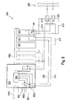
- FIG. 5 shows a preferred embodiment of a device according to the invention for the safety-related shutdown of a segment circuit which does not have this disadvantage.
- a further segment circle is denoted overall by 500. It is initiated by a preferred embodiment 501 of the safety clamp according to the invention.
- the safety terminal 501 has an internal control unit 504, which contains inter alia two microcontrollers (not shown). Furthermore, the safety clamp 501 has first and second switching elements 505a; 505b, which are formed as a semiconductor switch. The safety terminal 501 is connected on the input side to the inline bus 105b. Furthermore, the safety terminal 501 has an input 502 for the power supply, eg 24 V, as well as an input 503 for the ground supply. According to the invention, a semiconductor switch 505 a is formed to interrupt the power supply line 210, whereas the second semiconductor switch 505 b is configured to cut off the ground supply line 514.
- the safety-related segment circuit has the inline bus 105c via which the input terminal 123, the Power terminal 211 and the output terminal 124 are connected to the safety terminal 501.
- the supply of the output terminal 124 via the supply terminal 211 is made. It is understood that the output terminal 124 can also be connected to the supply voltage and the ground supply via internal terminal lines.
- the output terminal 124 connects the power supply line 210 to the output line 215 via the switching element 130 that is controllable via the inline bus 105c. Similarly, the output terminal 124 connects the ground supply line 514 to the ground line 214. The lines 214 and 215 are in turn connected to the contactors 212 and 213 connected.
- the contactors 212, 213 can also be switched off in two-channel fashion in the illustration shown, with the first disconnection path being realized via the inline bus 105c and the disconnection of the switching element 130.
- the second turn-off path is realized by means of the semiconductor switches 505a and 505b, whereby the power supply line 210 and the Masseversorgüngs Koch 514 are switched off. Due to the measure according to the invention, also the ground supply can be switched off, a short circuit of the output line 215 against the voltage supply can not impair the safety functionality of the segment circuit.
- the described embodiment of the invention offers the advantage that standard fieldbus terminals can continue to be used.
Landscapes
- Engineering & Computer Science (AREA)
- Physics & Mathematics (AREA)
- General Physics & Mathematics (AREA)
- Automation & Control Theory (AREA)
- Computer Networks & Wireless Communication (AREA)
- Signal Processing (AREA)
- Safety Devices In Control Systems (AREA)
- Programmable Controllers (AREA)
Applications Claiming Priority (1)
| Application Number | Priority Date | Filing Date | Title |
|---|---|---|---|
| DE102005061152.4A DE102005061152B4 (de) | 2005-12-21 | 2005-12-21 | Vorrichtung und Verfahren zur sicherheitsgerichteten Abschaltung eines Segmentkreises in einem Feldbus |
Publications (1)
| Publication Number | Publication Date |
|---|---|
| EP1801675A1 true EP1801675A1 (fr) | 2007-06-27 |
Family
ID=37944099
Family Applications (1)
| Application Number | Title | Priority Date | Filing Date |
|---|---|---|---|
| EP06022785A Withdrawn EP1801675A1 (fr) | 2005-12-21 | 2006-11-02 | Dispositif et procédé destinés à la déconnection sécurisée d'un segment dans un bus de terrain |
Country Status (2)
| Country | Link |
|---|---|
| EP (1) | EP1801675A1 (fr) |
| DE (1) | DE102005061152B4 (fr) |
Cited By (2)
| Publication number | Priority date | Publication date | Assignee | Title |
|---|---|---|---|---|
| DE102009060662A1 (de) | 2009-12-22 | 2011-07-14 | Robert Bosch GmbH, 70469 | Einrichtung und Verfahren zum Testen der Versorgung eines elektrischen Verbrauchers |
| CN108020401A (zh) * | 2016-10-31 | 2018-05-11 | 北京新长征天高智机科技有限公司 | 一种基于pxi总线的多自由度机械臂测试系统 |
Families Citing this family (2)
| Publication number | Priority date | Publication date | Assignee | Title |
|---|---|---|---|---|
| DE102010018617A1 (de) | 2010-04-28 | 2011-11-03 | Robert Bosch Gmbh | Verfahren und Vorrichtung zum Überwachen einer Mehrzahl von Sensorsignalen |
| DE102016125382A1 (de) | 2016-12-22 | 2018-06-28 | Phoenix Contact Gmbh & Co. Kg | Modulare Schaltschützanordnung |
Citations (4)
| Publication number | Priority date | Publication date | Assignee | Title |
|---|---|---|---|---|
| EP0342614A1 (fr) * | 1988-05-17 | 1989-11-23 | ELECTRICAL SAFETY COMPANY S.r.l. | Alimentation de sécurité pour machines électriques mobiles |
| EP0883045A2 (fr) * | 1997-06-06 | 1998-12-09 | Allen-Bradley Company, LLC | Basse tension pour un système de commande industrielle à fonctionnement intrinséque sûr |
| DE10011211A1 (de) * | 2000-03-08 | 2001-09-20 | Pilz Gmbh & Co | Sicherheitsschaltgerät und Sicherheitsschaltgeräte-System |
| WO2002013388A2 (fr) * | 2000-08-09 | 2002-02-14 | Siemens Aktiengesellschaft | Procede pour exploiter un dispositif de commutation de securite et dispositif de commutation de securite |
-
2005
- 2005-12-21 DE DE102005061152.4A patent/DE102005061152B4/de not_active Expired - Fee Related
-
2006
- 2006-11-02 EP EP06022785A patent/EP1801675A1/fr not_active Withdrawn
Patent Citations (4)
| Publication number | Priority date | Publication date | Assignee | Title |
|---|---|---|---|---|
| EP0342614A1 (fr) * | 1988-05-17 | 1989-11-23 | ELECTRICAL SAFETY COMPANY S.r.l. | Alimentation de sécurité pour machines électriques mobiles |
| EP0883045A2 (fr) * | 1997-06-06 | 1998-12-09 | Allen-Bradley Company, LLC | Basse tension pour un système de commande industrielle à fonctionnement intrinséque sûr |
| DE10011211A1 (de) * | 2000-03-08 | 2001-09-20 | Pilz Gmbh & Co | Sicherheitsschaltgerät und Sicherheitsschaltgeräte-System |
| WO2002013388A2 (fr) * | 2000-08-09 | 2002-02-14 | Siemens Aktiengesellschaft | Procede pour exploiter un dispositif de commutation de securite et dispositif de commutation de securite |
Cited By (2)
| Publication number | Priority date | Publication date | Assignee | Title |
|---|---|---|---|---|
| DE102009060662A1 (de) | 2009-12-22 | 2011-07-14 | Robert Bosch GmbH, 70469 | Einrichtung und Verfahren zum Testen der Versorgung eines elektrischen Verbrauchers |
| CN108020401A (zh) * | 2016-10-31 | 2018-05-11 | 北京新长征天高智机科技有限公司 | 一种基于pxi总线的多自由度机械臂测试系统 |
Also Published As
| Publication number | Publication date |
|---|---|
| DE102005061152A1 (de) | 2007-06-28 |
| DE102005061152B4 (de) | 2015-12-17 |
Similar Documents
| Publication | Publication Date | Title |
|---|---|---|
| EP2017868B1 (fr) | Etage de sortie de puissance triphasée | |
| EP2089892B1 (fr) | Dispositif à commutateur de sécurité | |
| EP2727125B1 (fr) | Démarreur de moteur fiable | |
| WO2001067610A1 (fr) | Appareil de commutation de securite et systeme d'appareils de commutation de securite | |
| AT507540B1 (de) | Verfahren zur ansteuerung einer gleichstrommaschine | |
| EP2045683B1 (fr) | Dispositif et procédé pour tester des actionneurs redondants dans un circuit d'alimentation de sécurité | |
| EP3266031B1 (fr) | Dispositif de commutation permettant de faire fonctionner au moins une charge | |
| EP1364459B1 (fr) | Dispositif de commutation de securite | |
| WO2014187634A2 (fr) | Circuit de protection pour un actionneur, dispositif actionneur et procédé pour faire fonctionner un actionneur electrique | |
| DE102005061152B4 (de) | Vorrichtung und Verfahren zur sicherheitsgerichteten Abschaltung eines Segmentkreises in einem Feldbus | |
| DE102015206483A1 (de) | Schaltvorrichtung und Betriebsverfahren hierfür | |
| EP1594021B1 (fr) | Dispositif de circuit et procédé de test de contacts de commutation d'un circuit numérique de sortie | |
| EP2369694B1 (fr) | Dispositif de raccordement et appareil d'automatisation | |
| EP1968089B1 (fr) | Module de contrôle pour un coupe-circuit électrique, son procédé de fonctionnement et système de protection électrique | |
| EP2079141B1 (fr) | Dispositif de démarrage pour un moteur électrique doté d'une technique de sécurité intégrée | |
| EP3414637B1 (fr) | Dispositif de commutation de sécurité | |
| DE102022108193A1 (de) | Schaltverstärker für Sicherheitsanwendungen und Verfahren zum Betreiben eines Schaltverstärkers für Sicherheitsanwendungen | |
| DE102009060662A1 (de) | Einrichtung und Verfahren zum Testen der Versorgung eines elektrischen Verbrauchers | |
| DE202017006695U1 (de) | Elektronische Leitungsschutzschaltung sowie Leitungsschutzsystem | |
| WO2015180806A1 (fr) | Relais électronique | |
| EP3660597B1 (fr) | Dispositif pour une commutation d'un système de machine dangereuse | |
| BE1032100B1 (de) | Schutzschalter mit mechanischem Wechselschalter und Überwachungseinrichtung | |
| DE4405052A1 (de) | Sicherheitsschaltungsanordnung mit wenigstens einem Not-Aus-Schalter | |
| WO2025114203A1 (fr) | Module de sécurité pour dispositif électrique et son procédé de fonctionnement | |
| EP4686022A1 (fr) | Dispositif de sécurité électrique |
Legal Events
| Date | Code | Title | Description |
|---|---|---|---|
| PUAI | Public reference made under article 153(3) epc to a published international application that has entered the european phase |
Free format text: ORIGINAL CODE: 0009012 |
|
| AK | Designated contracting states |
Kind code of ref document: A1 Designated state(s): AT BE BG CH CY CZ DE DK EE ES FI FR GB GR HU IE IS IT LI LT LU LV MC NL PL PT RO SE SI SK TR |
|
| AX | Request for extension of the european patent |
Extension state: AL BA HR MK YU |
|
| 17P | Request for examination filed |
Effective date: 20071227 |
|
| 17Q | First examination report despatched |
Effective date: 20080204 |
|
| AKX | Designation fees paid |
Designated state(s): AT BE BG CH CY CZ DE DK EE ES FI FR GB GR HU IE IS IT LI LT LU LV MC NL PL PT RO SE SI SK TR |
|
| GRAP | Despatch of communication of intention to grant a patent |
Free format text: ORIGINAL CODE: EPIDOSNIGR1 |
|
| GRAC | Information related to communication of intention to grant a patent modified |
Free format text: ORIGINAL CODE: EPIDOSCIGR1 |
|
| GRAS | Grant fee paid |
Free format text: ORIGINAL CODE: EPIDOSNIGR3 |
|
| STAA | Information on the status of an ep patent application or granted ep patent |
Free format text: STATUS: THE APPLICATION HAS BEEN WITHDRAWN |
|
| 18W | Application withdrawn |
Effective date: 20091201 |