EP1801816A2 - USB cable unit and electronic device using the same - Google Patents
USB cable unit and electronic device using the same Download PDFInfo
- Publication number
- EP1801816A2 EP1801816A2 EP06077081A EP06077081A EP1801816A2 EP 1801816 A2 EP1801816 A2 EP 1801816A2 EP 06077081 A EP06077081 A EP 06077081A EP 06077081 A EP06077081 A EP 06077081A EP 1801816 A2 EP1801816 A2 EP 1801816A2
- Authority
- EP
- European Patent Office
- Prior art keywords
- electronic device
- wires
- wire part
- cable unit
- usb cable
- Prior art date
- Legal status (The legal status is an assumption and is not a legal conclusion. Google has not performed a legal analysis and makes no representation as to the accuracy of the status listed.)
- Withdrawn
Links
Images


Classifications
-
- H—ELECTRICITY
- H01—ELECTRIC ELEMENTS
- H01B—CABLES; CONDUCTORS; INSULATORS; SELECTION OF MATERIALS FOR THEIR CONDUCTIVE, INSULATING OR DIELECTRIC PROPERTIES
- H01B7/00—Insulated conductors or cables characterised by their form
- H01B7/08—Flat or ribbon cables
- H01B7/0876—Flat or ribbon cables comprising twisted pairs
-
- H—ELECTRICITY
- H01—ELECTRIC ELEMENTS
- H01R—ELECTRICALLY-CONDUCTIVE CONNECTIONS; STRUCTURAL ASSOCIATIONS OF A PLURALITY OF MUTUALLY-INSULATED ELECTRICAL CONNECTING ELEMENTS; COUPLING DEVICES; CURRENT COLLECTORS
- H01R31/00—Coupling parts supported only by co-operation with counterpart
- H01R31/06—Intermediate parts for linking two coupling parts, e.g. adapter
-
- H—ELECTRICITY
- H01—ELECTRIC ELEMENTS
- H01B—CABLES; CONDUCTORS; INSULATORS; SELECTION OF MATERIALS FOR THEIR CONDUCTIVE, INSULATING OR DIELECTRIC PROPERTIES
- H01B11/00—Communication cables or conductors
- H01B11/02—Cables with twisted pairs or quads
- H01B11/06—Cables with twisted pairs or quads with means for reducing effects of electromagnetic or electrostatic disturbances, e.g. screens
- H01B11/10—Screens specially adapted for reducing interference from external sources
- H01B11/1091—Screens specially adapted for reducing interference from external sources with screen grounding means, e.g. drain wires
Definitions
- the present invention relates to a USB cable unit and an electronic device using the same and, more particularly, to a USB cable unit and an electronic device using the same supporting USB 2.0.
- USB universal serial bus
- the USB has been used for data transmission between a host and a client as well as between a host and various peripheral devices such as an input device, an output device, a scanner, a digital camera, or the like.
- the USB has been used for data transmission among units within an electronic device.
- the USB 2.0 can transmit data up to 480 Mbps and is superior to the USB 1.1 as well as compatible with a USB 1.1 device, the USB 2.0 has been extensively used.
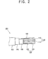
- FIG. 1 schematically illustrates a related art USB cable unit
- FIG. 2 is a sectional view illustrating the USB cable unit in FIG. 1.
- a USB cable unit 101 supports USB 2.0.
- the USB cable unit 101 includes a pair of power wires 110 and a pair of signal wires 120.
- the power wires 110 are non-twisted, and comprise a red Vbus wire 112 and a black ground wire 114.
- the signal wires 120 are twisted, and comprise a green D+ wire 122 and a white D- wire 124.
- An inner shield 130 integrally surrounds the power wires 110 and the signal wires 120.
- the inner shield 130 is formed of aluminized polyester and protects the power wires 110 and the signal wires 120.
- An outer shield 140 surrounds the inner shield 130, and is formed of 65% or more tinned copper braid to protect the power wires 110 and the signal wires 120 together with the inner shield 130.
- a covering member 150 surrounds the outer shield 140 to form the outer skin of the USB cable unit 101, and is formed of PVC (polyvinyl chloride).
- a drain wire 160 is formed of a tinned copper strand. With this configuration, the USB cable unit 101 can accomplish high/full speed to support the USB 2.0.
- USB cable unit 101 it is difficult to minimize the size of the USB cable unit 101 because of the big diameter required of the USB cable unit of this configuration, which makes it difficult to make slim a flat display device such as an electronic frame or the like, or other electronic devices. Also, the USB cable unit 101 is complicated, expensive and requires a lot of time for manufacturing.
- USB cable unit and an electronic device using the same supporting USB 2.0 with a high space-efficiency at a low cost.
- a USB cable unit for communicatably connecting a first electronic device and a second electronic device, comprising: a first wire part configured to connect the first electronic device and the second electronic device to transmit data therebetween; a second wire part configured to connect the first electronic device and the second electronic device to transmit data therebetween; and a third wire part comprising a power wire configured to connect the first electronic device and the second electronic device to transmit power therebetween, and a pair of ground wires ground to each other and configured to connect grounds of the first electronic device and the second electronic device.
- the third wire part comprises a third covering member integrally surrounding the power wire and the ground wires, and the ground wires contact each other to allow current to flow therebetween.
- the first wire part comprises a pair of first signal wires and a pair of first clock wires respectively configured to connect the first electronic device and the second electronic device, and a first covering member integrally surrounding the first signal wires and the first clock wires
- the second wire part comprises a pair of second signal wires and a pair of second clock wires respectively configured to connect the first electronic device and the second electronic device, and a second covering member integrally surrounding the second signal wires and the second clock wires.
- At least one of the first signal wires and the second signal wires are twisted.
- At least one of the first clock wires and the second clock wires are non-twisted.
- At least one of the first covering member, the second covering member and the third covering member comprise an aluminum tape.
- the USB cable unit further comprises a supporting member integrally surrounding the first wire part, the second wire part and the third wire part.
- the supporting member comprises aluminum tape.
- the first wire part, the second wire part and the third wire part are disposed on a plane.
- the first signal wires, the first clock wires, the second signal wires, the second clock wires, and the power wire and the ground wires are disposed on a plane.
- an electronic device comprising a first electronic device, a second electronic device, and a USB cable unit for communicatably connecting the first electronic device and the second electronic device
- the USB cable unit comprising: a first wire part connecting the first electronic device and the second electronic device to transmit data therebetween; a second wire part connecting the first electronic device and the second electronic device to transmit data therebetween; and a third wire part provided with a power wire connecting the first electronic device and the second electronic device to transmit power therebetween, and a pair of ground wires grounded each other to connect grounds of the first electronic device and the second electronic device.
- an electronic device 1 includes a first electronic device 200, a second electronic device 300 and a USB cable unit 100.
- the first electronic device 200 includes a control part 210 controlling a driving part 310.
- the control part 210 may comprise a MICOM or other type of processing unit.
- the second electronic device 300 includes the driving part 310.
- the driving part 310 receives a command from the control part 210 or transmits a signal thereto through the USB cable unit 100.
- the USB cable unit 100 connects the first electronic device 200 with the second electronic device 300 so that the first electronic device 200 communicates with the second electronic device 300.
- the USB cable unit 100 includes a first connector 110 connected to the first electronic device 200, a second connector 120 connected to the second electronic device 300, and a connecting part 130 connecting the first connector 110 with the second connector 120.
- the USB cable unit 100 supports USB 2.0.
- the first electronic device 200 is provided as a main printed circuit board installed in the electronic device 1, and the second electronic device 300 is provided as a sub printed circuit board installed therein.
- the second electronic device 300 may be an external device detachably connected to the electronic device 1.
- the first electronic device 200 and the second electronic device 300 may be embodied as other units that may communicate with each other to perform a function together.
- the electronic device 1 may be provided as an electronic frame displaying information.
- the electronic device 1 may be other flat display devices, or other portable devices such as a note book computer, a mobile telephone, an MP3 player, a digital camera, or the like.
- the electronic device 1 may be other devices using a USB connection.
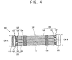
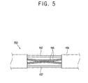
- FIG. 4 schematically illustrates the USB cable unit 100 of FIG. 3, and FIG. 5 illustrates a main portion A of FIG. 4, in which a covering member is removed.
- the USB cable unit 100 includes the first connector 110, the second connector 120 and the connecting part 130.
- the connecting part 130 includes a first wire part 140, a second wire part 150, a third wire part 160 and a supporting member 170.
- the first wire part 140 includes a pair of first signal wires 145 and a pair of first clock wires 142 respectively connecting the first electronic device 200 with the second electronic device 300, and a first covering member 148 integrally surrounding the first signal wires 145 and the first clock wires 142.
- the first clock wires 142 are non-twisted.
- the first signal wires 145 include a D+ wire and a D- wire which are twisted with each other.
- the first clock wires 142 and the first signal wires 145 are disposed parallel on a plane. Accordingly, the thickness of the first wire part 140 may be minimized.
- the first covering member 148 may support the first clock wires 142 and the first signal wires 145 and, additionally, may protect the first clock wires 142 and the first signal wires 145.
- the first covering member 148 may comprise an aluminum tape or a gasket, or may be formed of other insulating materials.
- the second wire part 150 includes a pair of second signal wires 155 and a pair of second clock wires 152 respectively connecting the first electronic device 200 with the second electronic device 300, and a second covering member 158 integrally surrounding the second signal wires 155 and the second clock wires 152.
- the second clock wires 152 are non-twisted.
- the second signal wires 155 include a D+ wire and a D- wire which are twisted each other.
- the second clock wires 152 and the second signal wires 155 are disposed parallel on a plane. Accordingly, the thickness of the second wire part 150 may be minimized. Also, the second clock wires 152 and the second signal wires 155 may be disposed on the same plane as the first wire part 140, and accordingly, the thickness of the first wire part 140 and the second wire part 150 may be minimized.
- the second covering member 158 may support the second clock wires 152 and the second signal wires 155 and, additionally, may protect the second clock wires 152 and the second signal wires 155.
- the second covering member 158 may comprise an aluminum tape or a gasket, or may be formed of other insulating materials.
- the first wire part 140 and the second wire part 150, respectively, may perform up streaming and down streaming.
- the third wire part 160 includes a pair of power wires 162 and a pair of ground wires 165 respectively connecting the first electronic device 200 with the second electronic device 300, and a third covering member 168 integrally surrounding the power wires 162 and the ground wires 165.
- the power wires 162 transmit power between the first electronic device 200 and the second electronic device 300.
- the ground wires 165 connect a ground of the first electronic device 200 with that of the second electronic device 300, and are grounded with each other by being surrounded with the third covering member 168. As illustrated in FIG. 5, the ground wires 165 contact each other, and skins of the contacted portion thereof are removed so that the ground wires 165 are grounded with each other.
- the power wires 162 and the ground wires 165 are respectively non-twisted.
- the power wires 162 and the ground wires 165 are disposed parallel on a plane so that the thickness of the third wire part 160 may be minimized. Also, the power wires 162 and the ground wires 165 are disposed on the same plane as the first wire part 140 and the second wire part 150 so that the total thickness of the connecting part 130 may be minimized.
- the third covering member 168 may support the power wires 162 and the ground wires 165 and, additionally, protect the power wires 162 and the ground wires 165.
- the third covering member 168 may comprise an aluminum tape or a gasket, or may be formed of other insulating materials.
- the supporting member 170 integrally surrounds the first wire part 140, the second wire part 150 and the third wire part 160 to support the first wire part 140, the second wire part 150 and the third wire part 160.
- a plurality of the supporting members 170 may be disposed at a various intervals or at predetermined intervals.
- the supporting member 170 may comprise an aluminum tape or a gasket, or may be formed of other materials.
- the USB cable unit 100 may prevent interference according to data transmission by including the first wire part 140, the second wire part 150, the third wire part 160 and the supporting member 170.
- the USB cable unit 100 may be configured to satisfy a termination impedance and through impedance (TDR) test and high speed specification (e.g., eye diagram, device receiver sensitivity), and accordingly may be configured to satisfy the USB 2.0 specification.
- TDR termination impedance and through impedance
- high speed specification e.g., eye diagram, device receiver sensitivity
- the USB cable unit 100 may be configures as a plate USB cable which is capable of supporting the USB 2.0, to thereby enable slimming of the electronic device 1.
- the configuration of the USB cable unit 100 is simplified in this configuration, the manufacturing cost and the manufacturing time for the USB cable unit 100 may be reduced.
- the first wire part 140, the second wire part 150 and the third wire part 160 are disposed parallel on the same plane, but alternatively, the first wire part 140, the second wire part 150 and the third wire part 160 can be disposed parallel on different planes.
- the first wire part 140, the second wire part 150 and the third wire part 160 respectively include the four wires, but alternatively, the first wire part 140, the second wire part 150 and the third wire part 160 can include other numbers of wires according to the connect between the first electronic device 200 and the second electronic device 300, or respectively include different numbers of wires.
- the USB cable unit 100 includes one first wire part 140 and one second wire part 150, but alternatively, at least one of the first wire part 140 and the second wire part 150 may be provided in plural.
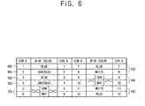
- FIG. 6 is a configuration table of the USB cable unit in FIG. 3.
- CON A represents the first connector 110
- CON B represents the second connector 120.
- the third wire part 160 includes the power wires 162 having a wire 1 and a wire 3, and the ground wires 165 having a wire 2 and a wire 4.
- the wires 1 and 3 are blue and not twisted with each other, and the wires 2 and 4 are black and not twisted with each other.
- the second wire part 150 includes the second signal wires 155 having a wire 5 and a wire 6, and the second clock wires 152 having a wire 7 and a wire 6.
- the wire 5 is green and the wire 6 is white, and both are twisted with each other.
- the wire 7 is blue and the wire 8 is white, and both are not twisted with each other.
- the first wire part 140 includes the first signal wires 145 having a wire 9 and a wire 10, and the first clock wires 142 having a wire 11 and a wire 12.
- the wire 9 is green and the wire 10 is white, and both are twisted with each other.
- the wire 11 is white and the wire 12 is blue, and both are not twisted each other.
- a UL1571 wire may be used as the wires 1, 3, 7 and 12, and a UL758 wire may be used as the wires 2 and 4. Also, a UL1589 wire may be used as the wires 5, 6, 9 and 10, and a UL1061 wire may be used as the wires 8 and 11.
- the exemplary embodiments of the present invention provide the USB cable unit and the electronic device using the same supporting the USB 2.0 with a high space-efficiency at a low cost.
Landscapes
- Physics & Mathematics (AREA)
- Electromagnetism (AREA)
- Insulated Conductors (AREA)
- Power Sources (AREA)
Abstract
Description
- This application claims priority from
Korean Patent Application No. 2005-0127261, filed on December 21, 2005 - The present invention relates to a USB cable unit and an electronic device using the same and, more particularly, to a USB cable unit and an electronic device using the same supporting USB 2.0.
- Recently, a universal serial bus (USB) which is convenient, easily extendable and capable of high speed data transmission, has been widely used. The USB has been used for data transmission between a host and a client as well as between a host and various peripheral devices such as an input device, an output device, a scanner, a digital camera, or the like. Also, the USB has been used for data transmission among units within an electronic device. Particularly, since the USB 2.0 can transmit data up to 480 Mbps and is superior to the USB 1.1 as well as compatible with a USB 1.1 device, the USB 2.0 has been extensively used.
- FIG. 1 schematically illustrates a related art USB cable unit, and FIG. 2 is a sectional view illustrating the USB cable unit in FIG. 1. In FIGS. 1 and 2, a
USB cable unit 101 supports USB 2.0. TheUSB cable unit 101 includes a pair ofpower wires 110 and a pair ofsignal wires 120. Thepower wires 110 are non-twisted, and comprise ared Vbus wire 112 and ablack ground wire 114. Thesignal wires 120 are twisted, and comprise agreen D+ wire 122 and a white D-wire 124. - An
inner shield 130 integrally surrounds thepower wires 110 and thesignal wires 120. Theinner shield 130 is formed of aluminized polyester and protects thepower wires 110 and thesignal wires 120. Anouter shield 140 surrounds theinner shield 130, and is formed of 65% or more tinned copper braid to protect thepower wires 110 and thesignal wires 120 together with theinner shield 130. A coveringmember 150 surrounds theouter shield 140 to form the outer skin of theUSB cable unit 101, and is formed of PVC (polyvinyl chloride). Adrain wire 160 is formed of a tinned copper strand. With this configuration, theUSB cable unit 101 can accomplish high/full speed to support the USB 2.0. - However, it is difficult to minimize the size of the
USB cable unit 101 because of the big diameter required of the USB cable unit of this configuration, which makes it difficult to make slim a flat display device such as an electronic frame or the like, or other electronic devices. Also, theUSB cable unit 101 is complicated, expensive and requires a lot of time for manufacturing. - Accordingly, it is an aspect of the present invention to provide a USB cable unit and an electronic device using the same supporting USB 2.0 with a high space-efficiency at a low cost.
- The foregoing and/or other aspects of the present invention can be achieved by providing a USB cable unit for communicatably connecting a first electronic device and a second electronic device, comprising: a first wire part configured to connect the first electronic device and the second electronic device to transmit data therebetween; a second wire part configured to connect the first electronic device and the second electronic device to transmit data therebetween; and a third wire part comprising a power wire configured to connect the first electronic device and the second electronic device to transmit power therebetween, and a pair of ground wires ground to each other and configured to connect grounds of the first electronic device and the second electronic device.
- According to an aspect of the present invention, the third wire part comprises a third covering member integrally surrounding the power wire and the ground wires, and the ground wires contact each other to allow current to flow therebetween.
- According to another aspect of the present invention, the first wire part comprises a pair of first signal wires and a pair of first clock wires respectively configured to connect the first electronic device and the second electronic device, and a first covering member integrally surrounding the first signal wires and the first clock wires, and the second wire part comprises a pair of second signal wires and a pair of second clock wires respectively configured to connect the first electronic device and the second electronic device, and a second covering member integrally surrounding the second signal wires and the second clock wires.
- According to another aspect of the present invention, at least one of the first signal wires and the second signal wires are twisted.
- According to another aspect of the present invention, at least one of the first clock wires and the second clock wires are non-twisted.
- According to another aspect of the present invention, at least one of the first covering member, the second covering member and the third covering member comprise an aluminum tape.
- According to another aspect of the present invention, the USB cable unit further comprises a supporting member integrally surrounding the first wire part, the second wire part and the third wire part.
- According to another aspect of the present invention, the supporting member comprises aluminum tape.
- According to another aspect of the present invention, the first wire part, the second wire part and the third wire part are disposed on a plane.
- According to another aspect of the present invention, the first signal wires, the first clock wires, the second signal wires, the second clock wires, and the power wire and the ground wires are disposed on a plane.
- The foregoing and/or other aspects of the present invention can be achieved by providing an electronic device comprising a first electronic device, a second electronic device, and a USB cable unit for communicatably connecting the first electronic device and the second electronic device, the USB cable unit comprising: a first wire part connecting the first electronic device and the second electronic device to transmit data therebetween; a second wire part connecting the first electronic device and the second electronic device to transmit data therebetween; and a third wire part provided with a power wire connecting the first electronic device and the second electronic device to transmit power therebetween, and a pair of ground wires grounded each other to connect grounds of the first electronic device and the second electronic device.
- The above and/or other aspects of the prevent invention will become apparent and more readily appreciated from the following description of the exemplary embodiments, taken in conjunction with the accompany drawings, in which:
- FIG. 1 schematically illustrates a related art USB cable unit;
- FIG. 2 is a sectional view illustrating the USB cable unit in FIG. 1;
- FIG. 3 schematically illustrates an electronic device including a USB cable unit according to an exemplary embodiment of the present invention;
- FIG. 4 schematically illustrates the USB cable unit in FIG. 3;
- FIG. 5 illustrates a main portion A in FIG. 4, in which a covering member is removed; and
- FIG. 6 is a configuration table of the USB cable unit in FIG. 3.
- Reference will now be made in detail to the exemplary embodiments of the present invention, examples of which are illustrated in the accompanying drawings, wherein like reference numerals refer to like elements throughout. The exemplary embodiments are described below so as to explain the various aspects of the present invention by referring to the figures.
- As shown in FIG. 3, an
electronic device 1 includes a firstelectronic device 200, a secondelectronic device 300 and aUSB cable unit 100. The firstelectronic device 200 includes acontrol part 210 controlling adriving part 310. Thecontrol part 210 may comprise a MICOM or other type of processing unit. The secondelectronic device 300 includes thedriving part 310. Thedriving part 310 receives a command from thecontrol part 210 or transmits a signal thereto through theUSB cable unit 100. - The
USB cable unit 100 connects the firstelectronic device 200 with the secondelectronic device 300 so that the firstelectronic device 200 communicates with the secondelectronic device 300. TheUSB cable unit 100 includes afirst connector 110 connected to the firstelectronic device 200, asecond connector 120 connected to the secondelectronic device 300, and a connectingpart 130 connecting thefirst connector 110 with thesecond connector 120. TheUSB cable unit 100 supports USB 2.0. - For purposes of illustration, the first
electronic device 200 is provided as a main printed circuit board installed in theelectronic device 1, and the secondelectronic device 300 is provided as a sub printed circuit board installed therein. Alternatively, the secondelectronic device 300 may be an external device detachably connected to theelectronic device 1. Also, alternatively, the firstelectronic device 200 and the secondelectronic device 300 may be embodied as other units that may communicate with each other to perform a function together. - The
electronic device 1 may be provided as an electronic frame displaying information. Alternatively, theelectronic device 1 may be other flat display devices, or other portable devices such as a note book computer, a mobile telephone, an MP3 player, a digital camera, or the like. Also, alternatively, theelectronic device 1 may be other devices using a USB connection. - FIG. 4 schematically illustrates the
USB cable unit 100 of FIG. 3, and FIG. 5 illustrates a main portion A of FIG. 4, in which a covering member is removed. As shown in FIG. 4, theUSB cable unit 100 includes thefirst connector 110, thesecond connector 120 and the connectingpart 130. The connectingpart 130 includes afirst wire part 140, asecond wire part 150, athird wire part 160 and a supportingmember 170. - The
first wire part 140 includes a pair offirst signal wires 145 and a pair offirst clock wires 142 respectively connecting the firstelectronic device 200 with the secondelectronic device 300, and a first coveringmember 148 integrally surrounding thefirst signal wires 145 and thefirst clock wires 142. Thefirst clock wires 142 are non-twisted. Thefirst signal wires 145 include a D+ wire and a D- wire which are twisted with each other. - The
first clock wires 142 and thefirst signal wires 145 are disposed parallel on a plane. Accordingly, the thickness of thefirst wire part 140 may be minimized. Thefirst covering member 148 may support thefirst clock wires 142 and thefirst signal wires 145 and, additionally, may protect thefirst clock wires 142 and thefirst signal wires 145. Thefirst covering member 148 may comprise an aluminum tape or a gasket, or may be formed of other insulating materials. - The
second wire part 150 includes a pair ofsecond signal wires 155 and a pair ofsecond clock wires 152 respectively connecting the firstelectronic device 200 with the secondelectronic device 300, and asecond covering member 158 integrally surrounding thesecond signal wires 155 and thesecond clock wires 152. Thesecond clock wires 152 are non-twisted. Thesecond signal wires 155 include a D+ wire and a D- wire which are twisted each other. - The
second clock wires 152 and thesecond signal wires 155 are disposed parallel on a plane. Accordingly, the thickness of thesecond wire part 150 may be minimized. Also, thesecond clock wires 152 and thesecond signal wires 155 may be disposed on the same plane as thefirst wire part 140, and accordingly, the thickness of thefirst wire part 140 and thesecond wire part 150 may be minimized. Thesecond covering member 158 may support thesecond clock wires 152 and thesecond signal wires 155 and, additionally, may protect thesecond clock wires 152 and thesecond signal wires 155. Thesecond covering member 158 may comprise an aluminum tape or a gasket, or may be formed of other insulating materials. Thefirst wire part 140 and thesecond wire part 150, respectively, may perform up streaming and down streaming. - The
third wire part 160 includes a pair ofpower wires 162 and a pair ofground wires 165 respectively connecting the firstelectronic device 200 with the secondelectronic device 300, and athird covering member 168 integrally surrounding thepower wires 162 and theground wires 165. Thepower wires 162 transmit power between the firstelectronic device 200 and the secondelectronic device 300. - The
ground wires 165 connect a ground of the firstelectronic device 200 with that of the secondelectronic device 300, and are grounded with each other by being surrounded with thethird covering member 168. As illustrated in FIG. 5, theground wires 165 contact each other, and skins of the contacted portion thereof are removed so that theground wires 165 are grounded with each other. Thepower wires 162 and theground wires 165 are respectively non-twisted. - The
power wires 162 and theground wires 165 are disposed parallel on a plane so that the thickness of thethird wire part 160 may be minimized. Also, thepower wires 162 and theground wires 165 are disposed on the same plane as thefirst wire part 140 and thesecond wire part 150 so that the total thickness of the connectingpart 130 may be minimized. Thethird covering member 168 may support thepower wires 162 and theground wires 165 and, additionally, protect thepower wires 162 and theground wires 165. Thethird covering member 168 may comprise an aluminum tape or a gasket, or may be formed of other insulating materials. - The supporting
member 170 integrally surrounds thefirst wire part 140, thesecond wire part 150 and thethird wire part 160 to support thefirst wire part 140, thesecond wire part 150 and thethird wire part 160. A plurality of the supportingmembers 170 may be disposed at a various intervals or at predetermined intervals. The supportingmember 170 may comprise an aluminum tape or a gasket, or may be formed of other materials. - The
USB cable unit 100 may prevent interference according to data transmission by including thefirst wire part 140, thesecond wire part 150, thethird wire part 160 and the supportingmember 170. TheUSB cable unit 100 may be configured to satisfy a termination impedance and through impedance (TDR) test and high speed specification (e.g., eye diagram, device receiver sensitivity), and accordingly may be configured to satisfy the USB 2.0 specification. Thus, since the thickness of theUSB cable unit 100 may be minimized, theUSB cable unit 100 may be configures as a plate USB cable which is capable of supporting the USB 2.0, to thereby enable slimming of theelectronic device 1. Also, since the configuration of theUSB cable unit 100 is simplified in this configuration, the manufacturing cost and the manufacturing time for theUSB cable unit 100 may be reduced. - Referring to FIGS. 3 through 5, the
first wire part 140, thesecond wire part 150 and thethird wire part 160 are disposed parallel on the same plane, but alternatively, thefirst wire part 140, thesecond wire part 150 and thethird wire part 160 can be disposed parallel on different planes. Also, thefirst wire part 140, thesecond wire part 150 and thethird wire part 160 respectively include the four wires, but alternatively, thefirst wire part 140, thesecond wire part 150 and thethird wire part 160 can include other numbers of wires according to the connect between the firstelectronic device 200 and the secondelectronic device 300, or respectively include different numbers of wires. Also, theUSB cable unit 100 includes onefirst wire part 140 and onesecond wire part 150, but alternatively, at least one of thefirst wire part 140 and thesecond wire part 150 may be provided in plural. - FIG. 6 is a configuration table of the USB cable unit in FIG. 3. Here, CON A represents the
first connector 110, and CON B represents thesecond connector 120. - Referring to FIG. 6, the
third wire part 160 includes thepower wires 162 having awire 1 and awire 3, and theground wires 165 having awire 2 and awire 4. Thewires wires - The
second wire part 150 includes thesecond signal wires 155 having awire 5 and awire 6, and thesecond clock wires 152 having awire 7 and awire 6. Thewire 5 is green and thewire 6 is white, and both are twisted with each other. Thewire 7 is blue and thewire 8 is white, and both are not twisted with each other. - The
first wire part 140 includes thefirst signal wires 145 having awire 9 and awire 10, and thefirst clock wires 142 having awire 11 and awire 12. Thewire 9 is green and thewire 10 is white, and both are twisted with each other. Thewire 11 is white and thewire 12 is blue, and both are not twisted each other. - A UL1571 wire may be used as the
wires wires wires wires - As described above, the exemplary embodiments of the present invention provide the USB cable unit and the electronic device using the same supporting the USB 2.0 with a high space-efficiency at a low cost.
- Although a few exemplary embodiments of the present invention have been shown and described, it will be appreciated by those skilled in the art that changes may be made in these embodiments without departing from the principles and spirit of the invention, the scope of which is defined in the appended claims and their equivalents.
Claims (19)
- A universal serial bus (USB) cable unit for communicatably connecting a first electronic device and a second electronic device, comprising:a first wire part configured to connect the first electronic device and the second electronic device to transmit data therebetween;a second wire part configured to connect the first electronic device and the second electronic device to transmit data therebetween; anda third wire part comprising:a power wire configured to connect the first electronic device and the second electronic device to transmit power therebetween; anda pair of ground wires grounded to each other and configured to connect grounds of the first electronic device and the second electronic device.
- The USB cable unit according to claim 1, wherein the third wire part comprises a third covering member integrally surrounding the power wire and the ground wires,
wherein the ground wires contact each other to allow current to flow therebetween. - The USB cable unit according to claim 1, wherein the first wire part comprises a pair of first signal wires and a pair of first clock wires respectively configured to connect the first electronic device and the second electronic device, and a first covering member integrally surrounding the first signal wires and the first clock wires, and
the second wire part comprises a pair of second signal wires and a pair of second clock wires respectively configured to connect the first electronic device and the second electronic device, and a second covering member integrally surrounding the second signal wires and the second clock wires. - The USB cable unit according to claim 3, wherein at least one of the first signal wires and the second signal wires are twisted.
- The USB cable unit according to claim 3, wherein at least one of the first clock wires and the second clock wires are non-twisted.
- The USB cable unit according to claim 3, wherein at least one of the first covering member, the second covering member and the third covering member comprise an aluminum tape.
- The USB cable unit according to claim 3, further comprising a supporting member integrally surrounding the first wire part, the second wire part and the third wire part.
- The USB cable unit according to claim 7, wherein the supporting member comprises aluminum tape.
- The USB cable unit according to claim 3, wherein the first wire part, the second wire part and the third wire part are disposed on a plane.
- The USB cable unit according to claim 3, wherein the first signal wires, the first clock wires, the second signal wires, the second clock wires, and the power wire and the ground wires are disposed on a plane.
- The USB cable unit according to claim 2, wherein the first wire part comprises a pair of first signal wires and a pair of first clock wires respectively configured to connect the first electronic device and the second electronic device, and a first covering member integrally surrounding the first signal wires and the first clock wires,
wherein the second wire part comprises a pair of second signal wires and a pair of second clock wires respectively configured to connect the first electronic device and the second electronic device, and a second covering member integrally surrounding the second signal wires and the second clock wires. - The USB cable unit according to claim 11, wherein at least one of the first signal wires and the second signal wires are twisted.
- The USB cable unit according to claim 11, wherein at least one of the first clock wires and the second clock wires are non-twisted.
- The USB cable unit according to claim 11, wherein at least one of the first covering member, the second covering member and the third covering member comprise an aluminum tape.
- The USB cable unit according to claim 11, further comprising a supporting member integrally surrounding the first wire part, the second wire part and the third wire part.
- The USB cable unit according to claim 15, wherein the supporting member comprises an aluminum tape.
- The USB cable unit according to claim 11, wherein the first wire part, the second wire part and the third wire part are disposed on a plane.
- The USB cable unit according to claim 11, wherein the first signal wires, the first clock wires, the second signal wires, the second clock wires, and the power wire and the ground wires are disposed on a plane.
- An electronic device comprising a first electronic device, a second electronic device, and a USB cable unit communicatably connecting the first electronic device and the second electronic device, the USB cable unit comprising:a first wire part connecting the first electronic device and the second electronic device to transmit data therebetween;a second wire part connecting the first electronic device and the second electronic device to transmit data therebetween; anda third wire part provided with a power wire connecting the first electronic device and the second electronic device to transmit power therebetween, and a pair of ground wires grounded each other to connect grounds of the first electronic device and the second electronic device.
Applications Claiming Priority (1)
| Application Number | Priority Date | Filing Date | Title |
|---|---|---|---|
| KR1020050127261A KR101164821B1 (en) | 2005-12-21 | 2005-12-21 | Ink jet printing apparatus |
Publications (2)
| Publication Number | Publication Date |
|---|---|
| EP1801816A2 true EP1801816A2 (en) | 2007-06-27 |
| EP1801816A3 EP1801816A3 (en) | 2012-10-03 |
Family
ID=37969750
Family Applications (1)
| Application Number | Title | Priority Date | Filing Date |
|---|---|---|---|
| EP06077081A Withdrawn EP1801816A3 (en) | 2005-12-21 | 2006-11-23 | USB cable unit and electronic device using the same |
Country Status (4)
| Country | Link |
|---|---|
| US (1) | US7525046B2 (en) |
| EP (1) | EP1801816A3 (en) |
| KR (1) | KR101164821B1 (en) |
| CN (1) | CN100543883C (en) |
Cited By (1)
| Publication number | Priority date | Publication date | Assignee | Title |
|---|---|---|---|---|
| EP3591945A4 (en) * | 2017-03-24 | 2020-02-26 | Huawei Technologies Co., Ltd. | DOUBLE SHIELDED LAYER USB CONNECTOR |
Families Citing this family (11)
| Publication number | Priority date | Publication date | Assignee | Title |
|---|---|---|---|---|
| US20080155161A1 (en) * | 2006-12-22 | 2008-06-26 | Clifton Broumand | Smart cable option |
| CN102318014A (en) * | 2009-02-16 | 2012-01-11 | 株式会社藤仓 | Transmission cable |
| CA2757429C (en) * | 2009-04-03 | 2014-06-17 | Telefonix, Incorporated | Usb cable and method for producing the same |
| CN102243904A (en) * | 2010-05-10 | 2011-11-16 | 万泰光电(东莞)有限公司 | A USB type wire structure and its type wire cabled pair twist assembly device |
| DE202010014872U1 (en) * | 2010-11-02 | 2012-02-03 | Coninvers Gmbh | Electrical connection cable |
| TWM411681U (en) * | 2011-03-22 | 2011-09-11 | Tuton Technology Co Ltd | USB connector expansion module implemented through PCI-E bus |
| CN103390844A (en) * | 2012-05-09 | 2013-11-13 | 鸿富锦精密工业(武汉)有限公司 | Connector cable |
| JP6056574B2 (en) * | 2013-03-15 | 2017-01-11 | 株式会社リコー | Multi-core flat cable |
| WO2015059863A1 (en) * | 2013-10-24 | 2015-04-30 | 三洋電機株式会社 | Electrical cable and power supply device |
| CN111681807A (en) * | 2020-05-15 | 2020-09-18 | 乐庭电线工业(常州)有限公司 | Bending-resistant network data line and production process thereof |
| CN114039245B (en) * | 2021-11-22 | 2025-09-12 | 中山立杰精密器材有限公司 | Transmission line structure and manufacturing process |
Family Cites Families (9)
| Publication number | Priority date | Publication date | Assignee | Title |
|---|---|---|---|---|
| US5053583A (en) | 1989-01-18 | 1991-10-01 | Amp Incorporated | Bundled hybrid ribbon electrical cable |
| US6211649B1 (en) | 1999-03-25 | 2001-04-03 | Sourcenext Corporation | USB cable and method for charging battery of external apparatus by using USB cable |
| JP4358353B2 (en) * | 1999-05-13 | 2009-11-04 | 日本圧着端子製造株式会社 | Balanced transmission shield cable |
| JP3686785B2 (en) | 1999-06-14 | 2005-08-24 | アルプス電気株式会社 | Signal cable |
| JP3871886B2 (en) | 2001-01-19 | 2007-01-24 | 沖電線株式会社 | Broadband shielded composite cable |
| KR200266081Y1 (en) | 2001-11-16 | 2002-02-27 | 최돈형 | The Cable Cord |
| DE10162739A1 (en) * | 2001-12-20 | 2003-07-03 | Nexans | Flexible electrical wire |
| KR200329963Y1 (en) | 2003-07-09 | 2003-10-17 | 김지환 | Cable equipment having charge and communication function between computer and potable device |
| US7432446B2 (en) | 2005-09-28 | 2008-10-07 | Symbol Technologies, Inc. | Coiled electronic article surveillance (EAS) cable |
-
2005
- 2005-12-21 KR KR1020050127261A patent/KR101164821B1/en not_active Expired - Fee Related
-
2006
- 2006-11-22 US US11/603,157 patent/US7525046B2/en not_active Expired - Fee Related
- 2006-11-23 EP EP06077081A patent/EP1801816A3/en not_active Withdrawn
- 2006-12-05 CN CNB2006101531501A patent/CN100543883C/en not_active Expired - Fee Related
Cited By (1)
| Publication number | Priority date | Publication date | Assignee | Title |
|---|---|---|---|---|
| EP3591945A4 (en) * | 2017-03-24 | 2020-02-26 | Huawei Technologies Co., Ltd. | DOUBLE SHIELDED LAYER USB CONNECTOR |
Also Published As
| Publication number | Publication date |
|---|---|
| US20070141873A1 (en) | 2007-06-21 |
| US7525046B2 (en) | 2009-04-28 |
| CN1988056A (en) | 2007-06-27 |
| KR20070066273A (en) | 2007-06-27 |
| CN100543883C (en) | 2009-09-23 |
| EP1801816A3 (en) | 2012-10-03 |
| KR101164821B1 (en) | 2012-07-12 |
Similar Documents
| Publication | Publication Date | Title |
|---|---|---|
| US7525046B2 (en) | USB cable unit and electronic device using the same | |
| US8878064B2 (en) | Flexible printed circuit board | |
| US10368437B2 (en) | Cable assembly for an information handling system | |
| WO1996006486A1 (en) | Multimedia computer keyboard | |
| US7441266B2 (en) | Wireless communication system utilizing wireless adapter | |
| CN210324144U (en) | Single-screen double-system switching display touch system for vehicle-mounted extension line expansion | |
| TW201813201A (en) | Flex flat cable structure and fixing structure of cable connector and flex flat cable | |
| US10283915B2 (en) | Connector and electronic device including the same | |
| US20040185719A1 (en) | Signal adaptor for USB and PS/2 connector | |
| KR102318130B1 (en) | External electrical connector and computer system | |
| EP3860097B1 (en) | Electronic device comprising conductive member disposed to have dielectric-fillable interval space along wire | |
| CN113032308A (en) | Multifunctional single-interface type electronic expansion equipment and external electronic expansion device | |
| KR101194365B1 (en) | Pannel connecting cable for display port | |
| US20090117777A1 (en) | Keyboard, video and mouse (kvm) switch | |
| EP3125656B1 (en) | Electronic device and display unit | |
| EP2814120A1 (en) | Radio frequency interference shield | |
| KR20010073533A (en) | Apparatus for connecting communication ports with external devices using a communication cable of mobile wireless phone | |
| US9917407B1 (en) | High-definition multimedia interface (HDMI) cable integrated with a media device | |
| WO2024198455A1 (en) | Display screen and electronic device | |
| CN111463535A (en) | Coaxial line assembly and mobile terminal | |
| KR20240002890A (en) | Electrostatic discharge protection circuit and electronic device including the same | |
| JP2001313130A (en) | Connector that groups contacts | |
| CN103330361A (en) | Protection sleeve for electronic equipment, and electronic equipment | |
| EP3813344B1 (en) | Electronic device for protecting components from surge voltage, and structure thereof | |
| KR200266081Y1 (en) | The Cable Cord |
Legal Events
| Date | Code | Title | Description |
|---|---|---|---|
| PUAI | Public reference made under article 153(3) epc to a published international application that has entered the european phase |
Free format text: ORIGINAL CODE: 0009012 |
|
| AK | Designated contracting states |
Kind code of ref document: A2 Designated state(s): AT BE BG CH CY CZ DE DK EE ES FI FR GB GR HU IE IS IT LI LT LU LV MC NL PL PT RO SE SI SK TR |
|
| AX | Request for extension of the european patent |
Extension state: AL BA HR MK YU |
|
| PUAL | Search report despatched |
Free format text: ORIGINAL CODE: 0009013 |
|
| RAP1 | Party data changed (applicant data changed or rights of an application transferred) |
Owner name: SAMSUNG ELECTRONICS CO., LTD. |
|
| AK | Designated contracting states |
Kind code of ref document: A3 Designated state(s): AT BE BG CH CY CZ DE DK EE ES FI FR GB GR HU IE IS IT LI LT LU LV MC NL PL PT RO SE SI SK TR |
|
| AX | Request for extension of the european patent |
Extension state: AL BA HR MK RS |
|
| RIC1 | Information provided on ipc code assigned before grant |
Ipc: H01B 7/08 20060101AFI20120827BHEP Ipc: H01B 11/10 20060101ALI20120827BHEP |
|
| AKY | No designation fees paid | ||
| REG | Reference to a national code |
Ref country code: DE Ref legal event code: R108 |
|
| REG | Reference to a national code |
Ref country code: DE Ref legal event code: R108 Effective date: 20130612 |
|
| STAA | Information on the status of an ep patent application or granted ep patent |
Free format text: STATUS: THE APPLICATION IS DEEMED TO BE WITHDRAWN |
|
| 18D | Application deemed to be withdrawn |
Effective date: 20130404 |