EP1801960A2 - Convertisseur de courant direct à courant direct bidirectionnel et procédé de contrôle - Google Patents
Convertisseur de courant direct à courant direct bidirectionnel et procédé de contrôle Download PDFInfo
- Publication number
- EP1801960A2 EP1801960A2 EP20060025565 EP06025565A EP1801960A2 EP 1801960 A2 EP1801960 A2 EP 1801960A2 EP 20060025565 EP20060025565 EP 20060025565 EP 06025565 A EP06025565 A EP 06025565A EP 1801960 A2 EP1801960 A2 EP 1801960A2
- Authority
- EP
- European Patent Office
- Prior art keywords
- switching
- directional
- converter
- voltage
- converting circuit
- Prior art date
- Legal status (The legal status is an assumption and is not a legal conclusion. Google has not performed a legal analysis and makes no representation as to the accuracy of the status listed.)
- Granted
Links
- 238000000034 method Methods 0.000 title claims description 7
- 238000004804 winding Methods 0.000 claims description 23
- 238000006243 chemical reaction Methods 0.000 claims description 12
- 238000012544 monitoring process Methods 0.000 claims description 6
- 230000002457 bidirectional effect Effects 0.000 claims description 3
- 230000010355 oscillation Effects 0.000 claims 1
- 230000001360 synchronised effect Effects 0.000 description 9
- 239000003990 capacitor Substances 0.000 description 8
- 230000000694 effects Effects 0.000 description 6
- 238000013461 design Methods 0.000 description 5
- 238000009499 grossing Methods 0.000 description 5
- 230000008929 regeneration Effects 0.000 description 3
- 238000011069 regeneration method Methods 0.000 description 3
- 229910044991 metal oxide Inorganic materials 0.000 description 2
- 150000004706 metal oxides Chemical class 0.000 description 2
- 230000002035 prolonged effect Effects 0.000 description 2
- 238000012790 confirmation Methods 0.000 description 1
- 239000010779 crude oil Substances 0.000 description 1
- 230000006866 deterioration Effects 0.000 description 1
- 238000007599 discharging Methods 0.000 description 1
- 230000005669 field effect Effects 0.000 description 1
- 238000012545 processing Methods 0.000 description 1
- 239000004065 semiconductor Substances 0.000 description 1
- 238000010792 warming Methods 0.000 description 1
Images


Classifications
-
- H—ELECTRICITY
- H02—GENERATION; CONVERSION OR DISTRIBUTION OF ELECTRIC POWER
- H02M—APPARATUS FOR CONVERSION BETWEEN AC AND AC, BETWEEN AC AND DC, OR BETWEEN DC AND DC, AND FOR USE WITH MAINS OR SIMILAR POWER SUPPLY SYSTEMS; CONVERSION OF DC OR AC INPUT POWER INTO SURGE OUTPUT POWER; CONTROL OR REGULATION THEREOF
- H02M3/00—Conversion of DC power input into DC power output
- H02M3/22—Conversion of DC power input into DC power output with intermediate conversion into AC
- H02M3/24—Conversion of DC power input into DC power output with intermediate conversion into AC by static converters
- H02M3/28—Conversion of DC power input into DC power output with intermediate conversion into AC by static converters using discharge tubes with control electrode or semiconductor devices with control electrode to produce the intermediate AC
- H02M3/325—Conversion of DC power input into DC power output with intermediate conversion into AC by static converters using discharge tubes with control electrode or semiconductor devices with control electrode to produce the intermediate AC using devices of a triode or a transistor type requiring continuous application of a control signal
- H02M3/335—Conversion of DC power input into DC power output with intermediate conversion into AC by static converters using discharge tubes with control electrode or semiconductor devices with control electrode to produce the intermediate AC using devices of a triode or a transistor type requiring continuous application of a control signal using semiconductor devices only
- H02M3/33569—Conversion of DC power input into DC power output with intermediate conversion into AC by static converters using discharge tubes with control electrode or semiconductor devices with control electrode to produce the intermediate AC using devices of a triode or a transistor type requiring continuous application of a control signal using semiconductor devices only having several active switching elements
- H02M3/33576—Conversion of DC power input into DC power output with intermediate conversion into AC by static converters using discharge tubes with control electrode or semiconductor devices with control electrode to produce the intermediate AC using devices of a triode or a transistor type requiring continuous application of a control signal using semiconductor devices only having several active switching elements having at least one active switching element at the secondary side of an isolation transformer
- H02M3/33584—Bidirectional converters
-
- B—PERFORMING OPERATIONS; TRANSPORTING
- B60—VEHICLES IN GENERAL
- B60L—PROPULSION OF ELECTRICALLY-PROPELLED VEHICLES; SUPPLYING ELECTRIC POWER FOR AUXILIARY EQUIPMENT OF ELECTRICALLY-PROPELLED VEHICLES; ELECTRODYNAMIC BRAKE SYSTEMS FOR VEHICLES IN GENERAL; MAGNETIC SUSPENSION OR LEVITATION FOR VEHICLES; MONITORING OPERATING VARIABLES OF ELECTRICALLY-PROPELLED VEHICLES; ELECTRIC SAFETY DEVICES FOR ELECTRICALLY-PROPELLED VEHICLES
- B60L58/00—Methods or circuit arrangements for monitoring or controlling batteries or fuel cells, specially adapted for electric vehicles
- B60L58/10—Methods or circuit arrangements for monitoring or controlling batteries or fuel cells, specially adapted for electric vehicles for monitoring or controlling batteries
- B60L58/18—Methods or circuit arrangements for monitoring or controlling batteries or fuel cells, specially adapted for electric vehicles for monitoring or controlling batteries of two or more battery modules
- B60L58/20—Methods or circuit arrangements for monitoring or controlling batteries or fuel cells, specially adapted for electric vehicles for monitoring or controlling batteries of two or more battery modules having different nominal voltages
-
- B—PERFORMING OPERATIONS; TRANSPORTING
- B60—VEHICLES IN GENERAL
- B60L—PROPULSION OF ELECTRICALLY-PROPELLED VEHICLES; SUPPLYING ELECTRIC POWER FOR AUXILIARY EQUIPMENT OF ELECTRICALLY-PROPELLED VEHICLES; ELECTRODYNAMIC BRAKE SYSTEMS FOR VEHICLES IN GENERAL; MAGNETIC SUSPENSION OR LEVITATION FOR VEHICLES; MONITORING OPERATING VARIABLES OF ELECTRICALLY-PROPELLED VEHICLES; ELECTRIC SAFETY DEVICES FOR ELECTRICALLY-PROPELLED VEHICLES
- B60L2210/00—Converter types
- B60L2210/10—DC to DC converters
-
- Y—GENERAL TAGGING OF NEW TECHNOLOGICAL DEVELOPMENTS; GENERAL TAGGING OF CROSS-SECTIONAL TECHNOLOGIES SPANNING OVER SEVERAL SECTIONS OF THE IPC; TECHNICAL SUBJECTS COVERED BY FORMER USPC CROSS-REFERENCE ART COLLECTIONS [XRACs] AND DIGESTS
- Y02—TECHNOLOGIES OR APPLICATIONS FOR MITIGATION OR ADAPTATION AGAINST CLIMATE CHANGE
- Y02T—CLIMATE CHANGE MITIGATION TECHNOLOGIES RELATED TO TRANSPORTATION
- Y02T10/00—Road transport of goods or passengers
- Y02T10/60—Other road transportation technologies with climate change mitigation effect
- Y02T10/70—Energy storage systems for electromobility, e.g. batteries
-
- Y—GENERAL TAGGING OF NEW TECHNOLOGICAL DEVELOPMENTS; GENERAL TAGGING OF CROSS-SECTIONAL TECHNOLOGIES SPANNING OVER SEVERAL SECTIONS OF THE IPC; TECHNICAL SUBJECTS COVERED BY FORMER USPC CROSS-REFERENCE ART COLLECTIONS [XRACs] AND DIGESTS
- Y02—TECHNOLOGIES OR APPLICATIONS FOR MITIGATION OR ADAPTATION AGAINST CLIMATE CHANGE
- Y02T—CLIMATE CHANGE MITIGATION TECHNOLOGIES RELATED TO TRANSPORTATION
- Y02T10/00—Road transport of goods or passengers
- Y02T10/60—Other road transportation technologies with climate change mitigation effect
- Y02T10/72—Electric energy management in electromobility
Definitions
- the present invention relates to a DC-DC converter that is provided between a first voltage power supply and a second voltage power supply and performs forward power conversion from a first voltage to a second voltage and backward power conversion from the second voltage to the first voltage.
- an HEV includes a main high-voltage battery for driving an engine assisting motor and an auxiliary low-voltage battery for supplying electric power to electronic devices mounted on the vehicle.
- the main high-voltage battery is charged when the engine rotates the motor and produces (regenerates) electric power.
- the generated electric power is converted by a DC-DC converter to electric power for the auxiliary low-voltage battery and supplied to the vehicle-mounted electronic devices.
- the main purpose of the DC-DC converter disposed between the main high-voltage battery and the auxiliary low-voltage battery is to cause a step-down operation from the main high-voltage battery to the auxiliary low-voltage battery.
- the engine may not be capable of being started due to a low voltage of the main high-voltage battery.
- the auxiliary low-voltage battery can compensate for the power insufficiency to start the engine through the main high-voltage battery alone. Accordingly, a bi-directional DC-DC converter having both a step-down function that serves from the high-voltage side to the low-voltage side and a step-up function that serves from the low-voltage side to the high-voltage side is demanded.
- a step-down ratio and a step-up ratio are determined by a ratio between the number of turns on the primary side of a transformer and the number of turns on the secondary side. If a ratio of the number of turns on the transformer that is optimum for a step-down operation is set, a problem of the inability to meet a step-up ratio arises. Conversely, if the step-up ratio is focused in setting a ratio of the number of turns on the transformer, another problem of a too low voltage during a step-down operation occurs. Even if a bi-directional DC-DC converter is structured without a transformer, when a difference between the step-down ratio and the step-up ratio is relatively large, desired bi-directional voltage ratios cannot be obtained easily.
- An object of the present invention is to provide a DC-DC converter, for bi-directionally converting electric power between two different voltages, from which a voltage is obtained across two terminals in a desired range even when a difference between its step-down ratio and step-up ratio is needed.
- a means for setting a duty ratio range for the step-down operation and a duty ratio range in the step-up operation separately is provided.
- a DC-DC converter which includes a transformer that connects a step-down conversion circuit and a step-up conversion circuit and converts electric power between two voltages, has a turns ratio switching means for switching the turns ratios of the transformer between the step-down operation and the step-up operation.
- the duty ratio range in PWM control can be adjusted independently for the step-down operation and the step-up operation by making a switching frequency during the step-down operation different from, for example, a switching frequency during the step-up operation. Accordingly, when the frequency for the step-down ratio or step-up ratio, whichever is insufficient, is set to a value lower than the frequency for the other (the cycle, that is, the length of time of one cycle, is prolonged) to expand the duty ratio range in PWM control, the adjustable range of the step-down ratio or the step-up ratio can be expanded.
- a duty ratio range adjusting means other than to adjust the switching frequency.
- the voltage range of the main high-voltage battery is determined according to the secondary battery mounted, required system specifications, and other factors.
- the voltage range of the auxiliary low-voltage battery is also determined similarly.
- control circuits Provided as control circuits are a step-down control circuit 4 for dropping the voltage from the HV side to the LV side, a step-up control circuit 5 for boosting the voltage, a switching frequency setting means 6 for a switching signal generated by the step-down control circuit 4, and a frequency setting means 7 for the step-up control circuit 5.
- Selectors 8 and 9 are also included; the selector 8 selectively selects a control signal sent from the step-down control circuit 4 and a control signal sent from the step-up control circuit 5 and sends the selected signal to the main high-voltage circuit 1; the selector 9 selectively selects a control signal sent from the step-down control circuit 4 and a control signal sent from the step-up control circuit 5 and sends the selected signal to the main low-voltage circuit 2.
- the above components excluding the power supplies HV and LV constitute the bi-directional DC-DC converter 10.
- the bi-directional DC-DC converter 10 is structured so that a step-down/step-up control switching signal 12 is received from a high-end controller 11 such as engine controller.
- the step-up control circuit 5 and switching frequency setting means 7 may or may not operate because they do not affect the step-down operation. To reduce the power consumption, however, the step-up control circuit 5 and switching frequency setting means 7 are preferably stopped. As such, the step-down operation from the high-voltage DC power supply HV to the low-voltage DC power supply LV is performed.
- the DC voltage of the LV is converted into an AC voltage in the main low-voltage circuit 2.
- the converted AC voltage is transferred by the transformer 3 to the HV and then rectified in the main high-voltage circuit 1.
- the switching means in the main low-voltage circuit 2 and main high-voltage circuit 1 are controlled by control signals generated in the step-up control circuit 5 and selected by the selectors 8 and 9.
- the step-down/step-up control switching signal 12 input from the selectors 8 and 9 from the high-end controller 11 commands a step-up operation.
- the step-up control circuit 5 generates controls signals to be supplied to the switching means, according to the switching frequency set by the switching frequency setting means 7.
- the step-down control circuit 4 and switching frequency setting means 6 may or may not operate because they do not affect the step-up operation. To reduce the power consumption, however, the step-down control circuit 4 and switching frequency setting means 6 are preferably stopped. As such, the step-up operation from the low-voltage DC power supply LV to the high-voltage DC power supply HV is performed.
- the switching means included in the main high-voltage circuit 1 and main low-voltage circuit 2 may be operated by diodes alone that are connected in parallel according to the operation, without having them perform a switching operation. This is because, during the rectification operation, for example, rectification by the diodes can basically achieve the purpose. When the switching means is turned on actively during the rectification operation, its purpose is usually to perform synchronous rectification with a switching device with less loss than the diode.
- a significant design parameter in FIG. 1 is the turns ratio of the transformer.
- the step-down ratio and step-up ratio are largely affected by the turns ratio of the transformer because the transformer is shared by the main high-voltage circuit 1 and main low-voltage circuit 2. If the turns ratio, for example, is determined with the step-down operation prioritized, a sufficient step-up ratio may not be obtained. Conversely, if the turns ratio is determined with the step-up operation prioritized, a sufficient step-down ratio cannot be obtained, resulting in a too low LV voltage.
- the above-mentioned switching frequencies during the step-down and step-up operations are set independently, so the step-down and step-up ratios can be set in a wide range.
- the switching frequencies fsw1 and fsw2 respectively set in the switching frequency setting means 6 and 7 are factory-set to unique values; they may be left unchanged after the product is shipped or may be changed during an operation after the shipping, according to the voltages of the HV and LV, the value of the load current (large or small), or another factor.
- FIGs. 3A to 3C show an example of the structure of the switching frequency setting means in the first embodiment.
- FIG. 4 shows a specific example of the structure of the step-down control circuit according to the first embodiment.
- FIG. 4 is the same as FIG. 1 except that the structure of the control system of the step-down control circuit 4 is depicted in detail.
- An error amplifier 111 amplifies the difference between the voltage of the low-voltage DC power supply LV and a reference voltage 112 and sends the amplified error to a PWM modulator (or PFM modulator) 110.
- the PWM modulator 110 performs PWM modulation (or PFM modulation) on the amplified result received from the error amplifier 111 and sends the resulting signal to the switching means in the main high-voltage circuit 1 and main low-voltage circuit 2.
- the step-up control circuit 5 in FIG. 1 is omitted in FIG.
- step-up control circuit 5 receives a voltage from the high-voltage DC power supply HV and outputs it to terminals, on the selectors 8 and 9, not used by the step-down control circuit 4.
- FIG. 5A illustrates first relation between the turns ratio of the transformer 3 and the frequencies fsw1 and fsw2 set by the switching frequency setting means 6 and 7.
- the transformer turns ratio (N1) required for dropping the voltage and the transformer turns ratio (N2) required for boosting the voltage are indicated on the horizontal axis.
- FIG. 5B illustrates second relation between the turns ratio of the transformer 3 and the frequencies fsw1 and fsw2 set by the switching frequency setting means 6 and 7.
- FIG. 5B shows an example in which the transformer turns ratios obtained from calculations of the step-down and step-up ratios cannot be originally satisfied simultaneously. In this case as well, either the step-down or step-up operation must be prioritized when transformer turns ratios are determined.
- the switching frequencies fsw1 and fsw2 are set as shown in FIG. 5B, the step-down and step-up ratios can be set in as wide a range as possible.
- the transformer turns ratio N2_2 actually required for the step-up operation is N2_2 N2/N2_1.
- the transformer turns ratio N2_2 required for the step-up operation refers to the step-up ratio required for the transformer itself (in this case, the step-up ratio is N2_2).
- the duty ratio width in PWM control can be expanded, widening the step-down or step-up ratio range.
- a switching frequency selected during a step-down operation and a switching frequency selected during a step-up operation are set independently to different values.
- a resulting effect is that the step-down and step-up ratios can be set in a wide range.
- Another effect is that since one more design parameter is used in a design of a bi-directional DC-DC converter, the design can be completed more quickly.
- FIG. 6 shows the entire structure of a bi-directional DC-DC converter according to a second embodiment of the present invention.
- the functional parts in FIG. 6 that are identical to the corresponding ones in FIG. 1 are assigned the same reference numerals to eliminate duplicate description.
- FIG. 6 differs from FIG. 1 in that a switching circuit 13 that switches between the switching frequencies fsw1 and fsw2 is provided.
- a switching frequency setting means 14 sets the switching frequency fsw1 according to an fsw1 switching signal 16 from the switching circuit 13.
- a switching frequency setting means 15 sets the switching frequency fsw2 according to an fsw2 switching signal 17 from the switching circuit 13.
- the switching circuit 13 is structured so that it receives the step-down/step-up control switching signal 12 sent from the high-end controller 11, a voltage signal 18 from the high-voltage DC power supply HV, and a voltage signal 19 from the low-voltage DC power supply LV. This completes the description of the structure of the bi-directional DC-DC converter 20.
- the basic operation in the second embodiment is similar to the one in the first embodiment in FIG. 1. Operations different from FIG. 1 will be described below.
- the switching frequencies fsw1 and fsw2 cannot be changed during operation; in FIG. 6, however, they can be changed.
- the switching frequency fsw1/fsw2 switching circuit 13 calculates a step-down or step-up ratio at that time from the voltage 18 of the high-voltage DC power supply HV and the voltage 19 of the low-voltage DC power supply LV.
- the switching circuit 13 can generate switching signals 16 and 17 for setting the required switching frequency fsw1 and fsw2 and send them to the switching frequency setting means 14 and 15.
- the switching frequency fsw1/fsw2 switching circuit 13 receives the step-down/step-up control switching signal 12 supplied from the high-end controller 11.
- the switching circuit 13 can thus switch between calculation for generating fsw1 and another calculation for generating fsw2.
- the switching frequency fsw1/fsw2 switching circuit 13 includes an independent calculation circuit for generating fsw1 and fsw2, the absence of the step-down/step-up control switching signal 12 causes no operational problem. If the step-down/step-up control switching signal 12 is input externally, there is no need to provide an independent calculation circuit for generating fsw1 and fsw2 in the switching circuit 13, providing an effect of structuring the switching circuit 13 with less hardware.
- FIG. 7 shows the entire structure of a bi-directional DC-DC converter according to a third embodiment of the present invention.
- the functional parts in FIG. 7 that are identical to the corresponding ones in FIG. 1 are assigned the same reference numerals to eliminate duplicate description.
- FIG. 7 differs from FIG. 1 in that the structure in FIG. 6 is further modified; an operation switching circuit 22 is provided, which receives a control signal 21 from the high-end controller 11 and switches the operation of the DC-DC converter 23.
- the control signal 21 from the high-end controller 11 includes a command for indicating a step-down or step-up operation and frequency setting information about the switching frequency fsw1 during the step-down operation and the switching frequency fsw2 during the step-up operation.
- the operation switching circuit 22 generates a step-down/step-up control switching signal 12 according to the control signal 21 from the high-end controller 11, and also generates switching signals 16 and 17 to be respectively sent to the switching frequency setting means 14 and 15.
- a bi-directional DC-DC converter can be operated according to a command from a high-end controller 11.
- the high-end controller 11 monitors the states of a high-voltage DC power supply HV and low-voltage DC power supply LV and controls an entire system in which the DC-DC converter 23 is mounted, so the high-end controller 11 can command the DC-DC converter to perform an optimum operation according to the state.
- FIG. 8 shows the entire structure of a bi-directional DC-DC converter according to a fourth embodiment of the present invention.
- the functional parts in FIG. 8 that are identical to the corresponding ones in FIG. 1 are assigned the same reference numerals to eliminate duplicate description.
- FIG. 8 differs from FIG. 1 in that the structure in FIG. 7 is further modified; an operation switching circuit 24 is structured so that it can make a switchover for the DC-DC converter 25 at its discretion, without receiving an external command.
- the operation switching circuit 24 respectively receives voltages 18 and 19 from the high-voltage DC power supply HV and low-voltage DC power supply LV, selects an operation mode in which the DC-DC converter 25 should operate according to the voltage values, and outputs a step-down/step-up control switching signal 12.
- the operation switching circuit 24 also generates switching signals 16 and 17 to be respectively sent to the switching frequency setting means 14 and 15.
- the operation switching circuit 24 sends a step-down control signal as the step-down/step-up control switching signal 12, and sends a switching frequency fsw1 switching signal suitable for the HV and LV voltages.
- the operation switching circuit 24 sends a step-up signal as the step-down/step-up control switching signal 12, and sends a switching frequency fsw2 switching signal suitable for the HV and LV voltages.
- the DC-DC converter 25 can perform control by itself according to the values of the voltages of the high-voltage DC power supply HV and low-voltage DC power supply LV, even when there is no signal from a high-end system.
- FIG. 9 shows the entire structure of a bi-directional DC-DC converter according to a fifth embodiment of the present invention.
- the functional parts in FIG. 9 that are identical to the corresponding ones in FIG. 1 are assigned the same reference numerals to eliminate duplicate description.
- FIG. 9 differs from FIG. 1 in that the structure in FIG. 6 is further modified; the bi-directional DC-DC converter further comprises a battery controller 26 for monitoring and controlling the state of the battery in the high-voltage DC power supply HV and a battery controller 27 for monitoring and controlling the state of the battery in the low-voltage DC power supply LV.
- An operation selecting circuit 28 receives a state signal 31 concerning the HV from the battery controller 26. Similarly, a signal line 30 connects the LV to the battery controller 27, and the battery controller 27 inputs a state signal 32 concerning the LV into the operation selecting circuit 28. The operation selecting circuit 28 thus switches between step-down control and step-up control of the bi-directional DC-DC converter 33, according to the states of the batteries of the high-voltage DC power supply HV and low-voltage DC power supply LV respectively sent from the battery controllers 26 and 27.
- the operation selecting circuit 28 receives the HV state signal 31 from the battery controller 26 and the LV state signal 32 from the batter controller 27, and outputs the step-down/step-up control signal 12, fsw1 switching signal 16, and fsw2 switching signal 17.
- the battery controllers 26 and 27, which monitor the states of the HV and LV batteries, enables precise switching between step-down control and step-up control and precise setting of the switching frequencies fsw1 and fsw2. Since signals can be received from battery controllers specific to battery state monitoring, processing for battery state confirmation does not need to be performed in the operation selecting circuit 28, providing an effect of reducing the size of the operation selecting circuit 28.
- FIG. 10 shows the entire structure of a bi-directional DC-DC converter according to a sixth embodiment of the present invention.
- the functional parts in FIG. 10 that are identical to the corresponding ones in FIG. 1 are assigned the same reference numerals to eliminate duplicate description.
- FIG. 10 differs from FIG. 9 in that a switching frequency switching means 34 is provided as a modified part. Other parts not shown are structured as shown in FIG. 9.
- the switching means 34 outputs a clock frequency switching signal 35 used to set frequencies for control signals generated by the step-down control circuit 4 and step-up control circuit 5.
- a clock frequency switching signal 36 is used to set the frequency of the clock signal 35.
- Reference numeral 37 indicates a bi-directional DC-DC converter.
- the step-down/step-up control switching signal 12 and clock frequency switching signal 36 are generated as illustrated in FIGs. 6 to 9.
- the step-down/step-up control switching signal 12 commands a voltage drop, so the frequency switching means 34 outputs a clock signal 35 for the step-down operation.
- the step-down control circuit 4 receives the clock signal 35 and outputs a control signal for the step-down operation.
- the control signal is supplied to the main high-voltage circuit 1 and main low-voltage circuit 2 through the selectors 8 and 9.
- the selectors 8 and 9 select a signal from the step-down control circuit 4 according to the step-down/step-up control switching signal 12, and output it.
- the clock signal 35 for step-down control is also supplied to the step-up control circuit 5, so the step-up control circuit 5 also outputs to the selectors a signal at the same frequency as the signal in the step-down control circuit 4.
- the selectors 8 and 9 have selected the signals from the step-down control circuit 4, causing no problem. It is also possible to use the step-down/step-up control switching signal 12 or the like to control the step-up control circuit 5 so that it does not operate.
- the frequency switching means 34 shown in FIG. 10 can function during both the step-down operation and step-up operation in a single circuit block, according to the step-down/step-up control switching signal 12 and clock signal 36. This idea can also be applied to the embodiments in FIGs. 6 to 9.
- FIG. 11 shows the entire structure of a bi-directional DC-DC converter according to a seventh embodiment of the present invention.
- the functional parts in FIG. 11 that are identical to the corresponding ones in FIG. 10 are assigned the same reference numerals to eliminate duplicate description. Only differences from FIG. 10 will be described.
- reference numerals 38 and 39 each indicate an OR circuit;
- reference numeral 40 indicates a step-down control circuit with an enable terminal;
- reference numeral 41 indicates a step-up control circuit with an enable terminal;
- reference numeral 42 indicates a bi-directional DC-DC converter.
- step-down/step-up control switching signal 12 and clock frequency switching signals 16 and 17 are generated as illustrated in FIGs. 6 to 9, so they are not shown.
- the step-down/step-up control switching signal 12 commands a voltage drop, so the step-down control circuit 40 operates and the step-up control circuit 41 does not operate.
- the step-up control circuit 41 is controlled so that when it is not operational, its output signal is low.
- the OR circuits 38 and 39 each OR the outputs of the step-down control circuit 40 and step-up control circuit 41 and send the resulting signal. Since the output of the step-up control circuit 41 is low, the output of the step-down control circuit 40 is sent to the main high-voltage circuit 1 and main low-voltage circuit 2.
- the switching frequency setting means 14 and 15 respectively supply a clock signal to the step-down control circuit 40 and step-up control circuit 41, according to the switching signals 16 and 17.
- the step-down/step-up control switching signal 12 commands voltage boosting, so the step-down control circuit 40 does not operate and the step-up control circuit 41 operates.
- the step-down control circuit 40 is controlled so that when it is not operational, its output signal is low.
- the OR circuits 38 and 39 each OR the outputs of the step-down control circuit 40 and step-up control circuit 41 and send the resulting signal. Since the output of the step-down control circuit 40 is low, the output of the step-up control circuit 41 is sent to the main high-voltage circuit 1 and main low-voltage circuit 2.
- the switching frequency setting means 14 and 15 respectively supply a clock signal to the step-down control circuit 40 and step-up control circuit 41, according to the switching signals 16 and 17.
- Enable signals are input to the step-down control circuit 40 and step-up control circuit 41 so that they do not operate actively when they do not need to operate, providing an effect of reducing the power consumption of the control circuits.
- a circuit for selecting a signal from the step-down control circuit 40 and a signal from the step-up control circuit 41 can be implemented as a simple OR circuit.
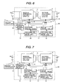
- FIG. 12 shows the entire structure of a bi-directional DC-DC converter according to an eighth embodiment of the present invention.
- the functional parts in FIG. 12 that are identical to the corresponding ones in FIG. 1 are assigned the same reference numerals to eliminate duplicate description.
- FIG. 12 shows examples of the internal structures of the main high-voltage circuit 1 and main low-voltage circuit 2 in FIG. 1.
- the structure of the main high-voltage circuit 1 will be described.
- a smoothing capacitor 43 Connected to the high-voltage DC power supply HV are a smoothing capacitor 43, a pair of switching devices 44 and 45 connected in series, and another pair of switching devices 46 and 47 connected in series.
- Freewheel diodes 48 to 51 are respectively connected to the switching devices 44 to 47 in parallel.
- the switching devices 44 to 47 are metal-oxide semiconductor field effect transistors (MOSFETs), body diodes can be used.
- MOSFETs metal-oxide semiconductor field effect transistors
- auxiliary reactor 52 adjusts the current gradient.
- the auxiliary reactor 52 may be replaced with a leak inductance of the transformer 3; in this case, the auxiliary reactor 52 can be eliminated.
- a current-doubler synchronous rectifier is used as the main low-voltage circuit.
- the current-doubler synchronous rectifier is well-known, as disclosed in, for example, Japanese Patent Laid-open No. 2003-199339 .
- Connected in parallel to the low-voltage DC power supply LV are a smoothing capacitor 61, a pair of a reactor 59 and switching device 56 connected in series, and another pair of a reactor 60 and switching device 55 connected in series; the smoothing capacitor 61 and the reactor 60 and switching device 55 pairs are connected in parallel.
- Freewheel diodes 58 and 57 are respectively connected to the switching devices 56 and 55 in parallel.
- the switching devices 56 and 55 are MOSFETs, body diodes can be used.
- the main low-voltage circuit 2 configured as the current-doubler circuit rectifies the AC voltage generated on the transformer 3 by using the diodes 57 and 58.
- the reactors 59 and 60 and the capacitor 61 smooth the rectified voltage to obtain a DC voltage LV.
- the switching devices 55 and 56 may be kept turned on while forward current flows from the anode to the cathode in each of the diodes 57 and 58, that is, so-called synchronous rectification may be performed.
- the switching devices 55 and 56 are turned on alternately to convert the DC voltage LV to an AC voltage and generate the AC voltage on the secondary winding 54 of the transformer 3.
- the generated AC voltage is converted according to the turns ratio of the transformer 3, and then rectified into a DC voltage by the main high-voltage circuit 1, resulting in a high DC voltage.
- MOSFETs are used as the switching devices, but switching devices such as insulated gate bipolar transistors (IGBTs) may be used without problems.
- IGBTs insulated gate bipolar transistors
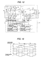
- FIG. 13 shows an example of timing charts when the step-down operation is performed in FIG. 12.
- the gate signals of the switching devices 44 to 47, 55, and 56 are indicated by A to F.
- the gate signals A and B have a period during which they are kept low concurrently so that both switching devices 44 and 45 are not turned on concurrently.
- the gate signals C and D have a period during which they are kept low concurrently so that both switching devices 46 and 47 are not turned on concurrently.
- a and C are controlled in such a way that they are shifted from each other. While both A and D are on and both B and C are on, a voltage is generated on the primary winding of the transformer 3 and electric power is supplied to the low-voltage side through the transformer 3.
- the switching devices 55 and 56 on the low-voltage side perform synchronous rectification according to the control signals E and F shown in FIG. 13 so that the AC voltage generated on the secondary winding of the transformer 3 is rectified.
- the switching frequency at that time is 1/T1.
- the switching frequency setting means 6 enables a switching frequency suitable for the step-down operation to be set without being affected by the step-up operation.
- FIG. 14 shows examples of timing charts when the step-up operation is performed in FIG. 12.
- the AC voltage generated on the primary winding of the transformer 3 is rectified by the diodes 48 to 51 with A to D turned off.
- the control signals E and F used to control the switching devices 55 and 56 on the low-voltage side are switched alternately as shown in FIG. 14 so as to generate an AC voltage on the secondary winding 54 of the transformer 3 and supply electric power to the high-voltage side.
- the switching frequency at that time is 1/T2.
- the switching frequency setting means 7 enables a switching frequency suitable for the step-up operation to be set without being affected by the step-down operation.
- FIG. 15 shows the entire structure of a bi-directional DC-DC converter according to a ninth embodiment of the present invention.
- the functional parts in FIG. 15 that are identical to the corresponding ones in FIG. 12 are assigned the same reference numerals to eliminate duplicate description.
- FIG. 15 differs from FIG. 12 in that the secondary winding of the transformer 62 has a center tap, at which the winding is divided into segments 63 and 64. Accordingly, the main low-voltage circuit is changed to a structure indicated by reference numeral 70.
- the main low-voltage circuit 70 comprises a reactor 65, switching devices 66 and 67, and diodes 68 and 69 connected in parallel to these switching devices.
- the switching devices 66 and 67 are metal-oxide MOSFETs
- body diodes can be used as the diodes 68 and 69.
- Timing charts for controlling the embodiment in FIG. 15 indicate operations similar to those in FIGs. 13 and 14.
- main high-voltage circuit and main low-voltage circuit are not limited to the circuits shown in these drawings, but any circuits that can operate as both an inverter and a rectifier can be used.
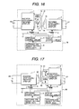
- FIG. 16 shows the entire structure of a bi-directional DC-DC converter according to a tenth embodiment of the present invention.
- the functional parts in FIG. 16 that are identical to the corresponding ones in FIG. 12 are assigned the same reference numerals to eliminate duplicate description.
- the bi-directional DC-DC converter 78 in the tenth embodiment is structured so that the transformer turns ratios are changed by switches 76 and 77 between the step-down operation and the step-up operation.
- the primary winding of the transformer 72 is divided into segments 73 and 74.
- the secondary winding is indicated by reference numeral 75.
- the switch 76 is turned on and the switch 77 is turned off so that only the segment 73 of the primary winding is used to reduce the turns ratio (N1) of the transformer 72.
- the switch 76 is turned off and the switch 77 is turned on so that the segments 73 and 74 of the primary winding are connected in series to increase the turns ratio (N2) of the transformer 72. Since the turns ratio of the transformer 72 is changed between the step-down operation and the step-up operation as described above, the step-down ratio and step-up ratio can be set to values optimal to the respective operations.
- the step-down control circuit 4 and step-up control circuit 5 are operated according to signals generated by the switching frequency setting means 6, so the switching frequencies during the step-down operation and the step-up operation are the same. Therefore, the transformer 72 is used to make a switchover between the step-down ratio and the step-up ratio.
- the operations in the tenth embodiment are the same as in the embodiment shown in FIG. 1 except that the turns ratios of the primary transformer are changed.
- FIG. 17 shows the entire structure of a bi-directional DC-DC converter according to an eleventh embodiment of the present invention.
- the functional parts in FIG. 17 that are identical to the corresponding ones in FIG. 16 are assigned the same reference numerals to eliminate duplicate description.
- the bi-directional DC-DC converter 85 in the eleventh embodiment is also structured so that the transformer turns ratios are switched between the step-down operation and the step-up operation.
- FIG. 17 differs from FIG. 16 in that the turns ratios are switched by switches 83 and 84 between the step-down operation and the step-up operation on the secondary winding side of the transformer 79.
- the primary winding 80 of the transformer 79 is divided into segments 81 and 82.
- Reference numeral 83 and 84 indicates switches, and reference numeral 85 indicates a bi-directional DC-DC converter.
- the switch 83 is turned off and the switch 84 is turned on so that the segments 81 and 82 of the secondary winding are connected in series to decrease the turns ratio (N1).
- the switch 83 is turned on and the switch 84 is turned off so that only the segment 81 of the secondary winding is used to increase the turns ratio (N2) of the transformer 79. This type of operation provides an effect similar to that in the tenth embodiment shown in FIG. 16.
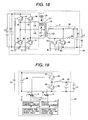
- FIG. 18 shows the entire structure of a bi-directional DC-DC converter according to a twelfth embodiment of the present invention.
- the functional parts in FIG. 18 that are identical to the corresponding ones in FIG. 12 are assigned the same reference numerals to eliminate duplicate description.
- the structure of the main circuit in FIG. 12 is used as the base, and the taps of the transformer are selectively used to switch reactor values and transformer turns ratios between the step-down operation and the step-up operation.
- the switch 136 is turned off and the switch 137 is turned on so that the auxiliary reactor 135 and primary winding 132 are operated effectively.
- the switch 136 is turned on and the switch 137 is turned off so that the auxiliary reactor 134 and the primary windings 131 and 132 are operated effectively. Accordingly, the auxiliary reactor value during the step-up operation is made small and the transformer turns ratios are made large, relative to the step-down operation.
- the reason why a small auxiliary reactor value is set during the step-up operation is that due to a voltage drop caused by the auxiliary reactor, the voltages generated on the primary windings 131 and 132 are not supplied effectively to the high-voltage DC power supply HV.
- FIG. 19 shows the entire structure of a bi-directional DC-DC converter according to a thirteenth embodiment of the present invention.
- the functional parts in FIG. 19 that are identical to the corresponding ones in the previous drawings are assigned the same reference numerals to eliminate duplicate description.
- the bi-directional DC-DC converter in the thirteenth embodiment is an example of a non-insulated bi-directional DC-DC converter that does not use a transformer for electric power conversion.
- Reference numeral 86 indicates a smoothing capacitor on the high-voltage side
- reference numerals 87 and 88 indicate switching devices
- reference numerals 89 and 90 indicate diodes.
- the switching devices 87 and 88 are MOSFETs
- body diodes can be used as the diodes 89 and 90.
- Reference numeral 91 indicates a reactor
- reference numeral 92 indicates a smoothing capacitor on the low-voltage side.
- the switching device 87 When the switching device 87 is operated during the step-down operation, electric power is sent from the HV side to the LV side. Specifically, when the switching device 87 is turned off, the current flowing in the reactor 91 causes the diode 90 to supply a forward current. At that time, the switch 88 can be turned on to perform synchronous rectification.
- the bi-directional DC-DC converter is indicated by reference numerals 93.
- FIG. 20 shows examples of timing charts when the bi-directional DC-DC converter according to the thirteenth embodiment of the present invention in FIG. 19 performs the step-down operation and step-up operation, assuming that synchronous rectification is performed.
- the switching frequency cycle during the step-down operation, given as T1 and the switching frequency cycle during the step-up operation, given as T2, can be controlled independently.
- the switching frequency during the step-down operation and the switching frequency during the step-up operation are controlled independently, it is possible in the non-insulated converter as well to set the step-down ratio and step-up ratio in a wide range.
- FIG. 21 shows, as a fourteenth embodiment of the present invention, a system structure in which a bi-directional DC-DC converter is applied to a vehicle-mounted hybrid system.
- Reference numeral 100 indicates an engine;
- reference numeral 101 indicates a motor/generator for powering and regeneration, which operates as the inverter during powering and operates as the generator during regeneration;
- reference numerals 102 indicates an inverter/converter, which operates as the inverter during powering and rotates a motor by using electric power of the high-voltage DC power supply HV, and operates as the converter during regeneration and converts the AC voltage generated by the generator and charges the high-voltage DC power supply HV.
- the bi-directional DC-DC converter 103 is disposed between the HV and the LV and performs bi-directional power conversion.
- An electronic unit 104 is mounted on the vehicle.
- Battery controllers 105 and 106 respectively control the power of the HV and LV.
- An electronic control unit ECU 106 functions as a high-end unit that controls the bi-directional DC-DC converter 103. Specifically, the ECU 106 switches the bi-directional DC-DC converter 103 between the step-down operation and the step-up operation, sends setting information about the switching frequency to the DC-DC converter 103, and receives the operation state and other information from the DC-DC converter 103.
- the battery controllers 105 and 106 and electronic control unit ECU 106 mutually communicate through a network 108 to transmit and receive information.
- the DC-DC converter 103 in the fourteenth embodiment communicates directly with the electronic control unit ECU 106. However, the DC-DC converter 103 may also use the network 108 to communicate with the electronic control unit ECU 106 and battery controllers 105 and 106.
- the DC-DC converter 103 functions to supply electric power to the vehicle-mounted electronic unit connected to the LV power supply and that, during the step-up operation, it functions as an emergency unit to start the engine when the voltage of the HV is lowered.
- the present invention is not limited to these applications but can be used to convert electric power between DC voltages.
- the high-voltage DC power supply and low-voltage power DC power supply described above are assumed to comprise a secondary battery, a capacitor, and other parts.
- the above embodiments of the present invention are effective in bi-directionally converting electric power between a high-voltage DC power supply and a low-voltage DC power supply in a vehicle-mounted system when there is a large difference in voltage between the power supplies and their voltages largely vary during an operation.
Landscapes
- Engineering & Computer Science (AREA)
- Power Engineering (AREA)
- Life Sciences & Earth Sciences (AREA)
- Sustainable Development (AREA)
- Sustainable Energy (AREA)
- Transportation (AREA)
- Mechanical Engineering (AREA)
- Dc-Dc Converters (AREA)
Applications Claiming Priority (1)
| Application Number | Priority Date | Filing Date | Title |
|---|---|---|---|
| JP2005367862A JP4719567B2 (ja) | 2005-12-21 | 2005-12-21 | 双方向dc−dcコンバータおよびその制御方法 |
Publications (3)
| Publication Number | Publication Date |
|---|---|
| EP1801960A2 true EP1801960A2 (fr) | 2007-06-27 |
| EP1801960A3 EP1801960A3 (fr) | 2008-11-19 |
| EP1801960B1 EP1801960B1 (fr) | 2011-07-13 |
Family
ID=37891713
Family Applications (1)
| Application Number | Title | Priority Date | Filing Date |
|---|---|---|---|
| EP20060025565 Ceased EP1801960B1 (fr) | 2005-12-21 | 2006-12-11 | Convertisseur de courant direct à courant direct bidirectionnel et procédé de contrôle |
Country Status (4)
| Country | Link |
|---|---|
| US (2) | US7692935B2 (fr) |
| EP (1) | EP1801960B1 (fr) |
| JP (1) | JP4719567B2 (fr) |
| CN (1) | CN100563085C (fr) |
Cited By (15)
| Publication number | Priority date | Publication date | Assignee | Title |
|---|---|---|---|---|
| US20100052423A1 (en) * | 2008-09-02 | 2010-03-04 | Hitachi Computer Peripherals Co., Ltd. | Bidirectional dc-dc converter and control method thereof |
| FR2977083A1 (fr) * | 2011-06-23 | 2012-12-28 | Peugeot Citroen Automobiles Sa | Architecture de batterie avec transmission magnetique de puissance et equilibrage en tension |
| EP2161823A4 (fr) * | 2007-06-28 | 2013-10-23 | Shindengen Electric Mfg | Convertisseur cc/cc bidirectionnel |
| EP2685619A1 (fr) * | 2012-07-11 | 2014-01-15 | MStar Semiconductor, Inc. | Utilisation d'énergie efficace dans des produits de faible puissance |
| EP2429070A3 (fr) * | 2010-09-10 | 2014-03-26 | OMRON Automotive Electronics Co., Ltd. | Convertisseur CC-CC avec une efficacité améliorée dans un réseau électrique bi-tension d'un véhicule |
| CN104303409A (zh) * | 2012-05-04 | 2015-01-21 | 阿尔斯通技术有限公司 | 用于输送hvdc电流的dc/dc转换器的非线性控制装置 |
| WO2015145232A1 (fr) * | 2014-03-28 | 2015-10-01 | Toyota Jidosha Kabushiki Kaisha | Convertisseur cc/cc et système de stockage électrique |
| EP2243211A4 (fr) * | 2008-02-22 | 2017-04-19 | Murata Power Solutions | Procédé et appareil pour conversion d alimentation avec plage de tension d entrée large |
| WO2017125204A1 (fr) * | 2016-01-20 | 2017-07-27 | Robert Bosch Gmbh | Convertisseur continu/continu bidirectionnel et procédé de charge du condensateur de circuit intermédiaire d'un convertisseur continu/continu de la batterie basse tension |
| EP3503136A1 (fr) * | 2017-12-21 | 2019-06-26 | Hamilton Sundstrand Corporation | Module de conversion de puissance à usages multiples |
| US10690705B2 (en) | 2016-06-15 | 2020-06-23 | Watlow Electric Manufacturing Company | Power converter for a thermal system |
| US10790739B1 (en) | 2019-05-29 | 2020-09-29 | Hamilton Sundstrand Corporation | Redundant power supply having diverse dual controllers |
| EP4068607A1 (fr) * | 2021-03-30 | 2022-10-05 | TDK Corporation | Appareil de conversion de puissance et système de conversion de puissance |
| EP4108496A1 (fr) | 2021-06-22 | 2022-12-28 | Samsung SDI Co., Ltd. | Système d'alimentation bidirectionnelle pour alimenter un système de gestion de batterie d'un véhicule électrique |
| US12191774B2 (en) | 2021-06-22 | 2025-01-07 | Samsung Sdi Co., Ltd. | Bidirectional power supply system for powering a battery management system of an electric vehicle |
Families Citing this family (104)
| Publication number | Priority date | Publication date | Assignee | Title |
|---|---|---|---|---|
| JP4719567B2 (ja) * | 2005-12-21 | 2011-07-06 | 日立オートモティブシステムズ株式会社 | 双方向dc−dcコンバータおよびその制御方法 |
| WO2007132667A1 (fr) * | 2006-05-15 | 2007-11-22 | Panasonic Corporation | Périphérique d'alimentation bidirectionnel |
| FI20075322A0 (fi) * | 2007-05-07 | 2007-05-07 | Nokia Corp | Teholähteitä RF-tehovahvistimelle |
| EP2019481A1 (fr) * | 2007-07-25 | 2009-01-28 | Danmarks Tekniske Universitet | Convertisseur CC-CC en mode commuté avec transformateurs d'alimentation multiple |
| JP4378400B2 (ja) * | 2007-08-28 | 2009-12-02 | 日立コンピュータ機器株式会社 | 双方向dc−dcコンバータ及び双方向dc−dcコンバータの制御方法 |
| TW200923631A (en) * | 2007-11-22 | 2009-06-01 | Inventec Corp | Apparatus and method for adjusting working frequency of VRD by detecting current |
| WO2009096073A1 (fr) * | 2008-01-28 | 2009-08-06 | Murata Manufacturing Co., Ltd. | Convertisseur cc-cc |
| JP5260092B2 (ja) * | 2008-03-10 | 2013-08-14 | 株式会社日立製作所 | 電力変換装置及び発電変換システム |
| JP4401418B2 (ja) | 2008-04-18 | 2010-01-20 | シャープ株式会社 | 双方向dc/dcコンバータおよびパワーコンディショナ |
| TW201013379A (en) * | 2008-09-18 | 2010-04-01 | Asustek Comp Inc | Frequency conversion for power supply of computer system |
| US8080973B2 (en) | 2008-10-22 | 2011-12-20 | General Electric Company | Apparatus for energy transfer using converter and method of manufacturing same |
| CN101741260A (zh) * | 2008-11-19 | 2010-06-16 | 鸿富锦精密工业(深圳)有限公司 | 电源装置和变压装置 |
| CN101499717B (zh) * | 2009-02-17 | 2010-10-20 | 浙江大学 | 一种四开关升降压直流-直流变换器的控制方法及装置 |
| US8148949B2 (en) | 2009-02-24 | 2012-04-03 | American Axle & Manufacturing, Inc. | Use of high frequency transformer to charge HEV batteries |
| US20100244773A1 (en) * | 2009-03-27 | 2010-09-30 | Gm Global Technology Operations, Inc. | Unity power factor isolated single phase matrix converter battery charger |
| JP5229139B2 (ja) * | 2009-07-07 | 2013-07-03 | 株式会社豊田自動織機 | 双方向dcdcコンバータ |
| US8466658B2 (en) * | 2009-08-05 | 2013-06-18 | GM Global Technology Operations LLC | Systems and methods for bi-directional energy delivery with galvanic isolation |
| US8350523B2 (en) * | 2009-08-05 | 2013-01-08 | GM Global Technology Operations LLC | Charging system with galvanic isolation and multiple operating modes |
| JP5461113B2 (ja) * | 2009-08-28 | 2014-04-02 | 富士重工業株式会社 | 双方向コンバータ及びこれを用いた電気自動車の制御装置 |
| US8288887B2 (en) * | 2009-11-19 | 2012-10-16 | GM Global Technology Operations LLC | Systems and methods for commutating inductor current using a matrix converter |
| US20110149611A1 (en) * | 2009-12-21 | 2011-06-23 | Intersil Americas Inc. | Bidirectional signal conversion |
| US8018740B2 (en) * | 2010-01-07 | 2011-09-13 | Texas Instruments Incorporated | LLC soft start by operation mode switching |
| JP5530212B2 (ja) * | 2010-02-10 | 2014-06-25 | 株式会社日立製作所 | 電源装置、ハードディスク装置、及び電源装置のスイッチング方法 |
| CN101777840B (zh) * | 2010-02-25 | 2012-06-06 | 北京航空航天大学 | 一种升降压复合dc/dc变换器 |
| US8410635B2 (en) * | 2010-03-16 | 2013-04-02 | GM Global Technology Operations LLC | Systems and methods for deactivating a matrix converter |
| DE102010029299B4 (de) | 2010-05-26 | 2023-06-29 | Robert Bosch Gmbh | Verfahren zum Betreiben eines Systems, System, Steuerung und Computergrogrammprodukt |
| US8462528B2 (en) | 2010-07-19 | 2013-06-11 | GM Global Technology Operations LLC | Systems and methods for reducing transient voltage spikes in matrix converters |
| JP5436364B2 (ja) * | 2010-08-09 | 2014-03-05 | オムロンオートモーティブエレクトロニクス株式会社 | Dcdcコンバータ |
| CN103098329A (zh) * | 2010-09-21 | 2013-05-08 | Abb技术有限公司 | 用于控制hvdc电力传输系统中的电力传输的设备 |
| US9290097B2 (en) | 2010-11-05 | 2016-03-22 | Robert Louis Steigerwald | Apparatus for transferring energy using onboard power electronics with high-frequency transformer isolation and method of manufacturing same |
| US8587962B2 (en) | 2010-11-08 | 2013-11-19 | GM Global Technology Operations LLC | Compensation for electrical converter nonlinearities |
| US8467197B2 (en) | 2010-11-08 | 2013-06-18 | GM Global Technology Operations LLC | Systems and methods for compensating for electrical converter nonlinearities |
| US8599577B2 (en) | 2010-11-08 | 2013-12-03 | GM Global Technology Operations LLC | Systems and methods for reducing harmonic distortion in electrical converters |
| US8614564B2 (en) | 2010-11-18 | 2013-12-24 | GM Global Technology Operations LLS | Systems and methods for providing power to a load based upon a control strategy |
| JP2012196082A (ja) * | 2011-03-17 | 2012-10-11 | Toyota Motor Corp | 電動車両 |
| US8860379B2 (en) | 2011-04-20 | 2014-10-14 | GM Global Technology Operations LLC | Discharging a DC bus capacitor of an electrical converter system |
| KR20150085072A (ko) | 2011-05-05 | 2015-07-22 | 아크틱 샌드 테크놀로지스, 인크. | 모듈형 단계들을 구비한 dc-dc 컨버터 |
| US10680515B2 (en) | 2011-05-05 | 2020-06-09 | Psemi Corporation | Power converters with modular stages |
| US8829858B2 (en) | 2011-05-31 | 2014-09-09 | GM Global Technology Operations LLC | Systems and methods for initializing a charging system |
| JP5403438B2 (ja) * | 2011-11-29 | 2014-01-29 | Tdk株式会社 | Dcdcコンバータ及びdcdcコンバータの制御方法 |
| JP5382552B2 (ja) * | 2011-11-18 | 2014-01-08 | Tdk株式会社 | Dcdcコンバータ及びdcdcコンバータの制御方法 |
| EP2724454B1 (fr) * | 2011-06-24 | 2015-10-07 | L-3 Communications Magnet-Motor GmbH | Convertisseur cc/cc galvano-isolé et procédé de commande d'un convertisseur cc/cc galvano-isolé |
| KR101214254B1 (ko) * | 2011-06-30 | 2012-12-21 | 한국에너지기술연구원 | 양방향 dc-dc 컨버터 |
| US9845012B2 (en) | 2011-07-06 | 2017-12-19 | General Electric Company | System and method for predicting mechanical failure of a motor |
| US8878495B2 (en) | 2011-08-31 | 2014-11-04 | GM Global Technology Operations LLC | Systems and methods for providing power to a load based upon a control strategy |
| US20130185947A1 (en) * | 2011-09-01 | 2013-07-25 | Robert Bosch Gmbh | Brushless dc motor-driven power device |
| JP5776482B2 (ja) * | 2011-10-11 | 2015-09-09 | トヨタ自動車株式会社 | 電動車両 |
| US8743553B2 (en) | 2011-10-18 | 2014-06-03 | Arctic Sand Technologies, Inc. | Power converters with integrated capacitors |
| JP5716638B2 (ja) * | 2011-11-04 | 2015-05-13 | 株式会社デンソー | 電力供給装置 |
| FR2982997B1 (fr) * | 2011-11-17 | 2013-12-20 | Commissariat Energie Atomique | Source de tension continue incluant des cellules electrochimiques a niveau de tension adaptatif |
| CN102403905A (zh) * | 2011-11-18 | 2012-04-04 | 江苏艾索新能源股份有限公司 | 双向dc/dc变换器 |
| CN202374182U (zh) * | 2011-11-25 | 2012-08-08 | 比亚迪股份有限公司 | Dc/dc双向转换器 |
| US8723491B2 (en) | 2011-12-19 | 2014-05-13 | Arctic Sand Technologies, Inc. | Control of power converters with capacitive energy transfer |
| EP2795758B1 (fr) * | 2011-12-21 | 2017-07-19 | ABB Schweiz AG | Dispositif pour commander la transmission de puissance dans un système de transmission électrique a courant continu haute tension |
| CN103187876B (zh) * | 2011-12-28 | 2016-08-03 | 艾默生网络能源有限公司 | 一种不间断电源的dc/dc电路 |
| JP5903628B2 (ja) * | 2012-06-14 | 2016-04-13 | パナソニックIpマネジメント株式会社 | 電力変換装置 |
| FR2992499B1 (fr) * | 2012-06-22 | 2014-06-20 | Valeo Sys Controle Moteur Sas | Procede de commande d'un convertisseur de tension continu/continu reversible |
| JP5420029B2 (ja) * | 2012-07-25 | 2014-02-19 | 三菱電機株式会社 | 双方向dc−dcコンバータおよび双方向dc−dcコンバータの制御方法 |
| JP5766356B2 (ja) * | 2012-08-08 | 2015-08-19 | 三菱電機株式会社 | 電力変換装置 |
| US9590519B2 (en) * | 2012-08-08 | 2017-03-07 | Apple Inc. | Power adapter with a step-down transformer and a voltage step-up circuit |
| JP5881553B2 (ja) * | 2012-08-09 | 2016-03-09 | 三菱電機株式会社 | 双方向dc/dcコンバータおよびこれを用いた車両用電源装置 |
| JP2014039383A (ja) * | 2012-08-14 | 2014-02-27 | Hitachi Automotive Systems Ltd | 電源装置および車載用電源装置 |
| US9130470B2 (en) * | 2012-09-14 | 2015-09-08 | General Electric Company | Power converter control system and method with separate primary and secondary controllers |
| JP6103874B2 (ja) * | 2012-10-12 | 2017-03-29 | 株式会社日立情報通信エンジニアリング | 電源装置とその運転方法 |
| CN102868198A (zh) * | 2012-10-12 | 2013-01-09 | 广东易事特电源股份有限公司 | Ups备用电源升压和充电复用电路 |
| KR101438610B1 (ko) * | 2012-12-28 | 2014-09-15 | 현대자동차 주식회사 | 충전기 및 그 구동 방법 |
| US9099932B2 (en) * | 2013-01-07 | 2015-08-04 | Analog Devices Global | Duty cycle balance module for switch mode power converter |
| JP6033092B2 (ja) * | 2013-01-11 | 2016-11-30 | 三菱電機株式会社 | 電源装置、led点灯装置およびバッテリ充電装置 |
| JP6024467B2 (ja) * | 2013-01-17 | 2016-11-16 | トヨタ自動車株式会社 | コンバータ制御装置 |
| US8619445B1 (en) | 2013-03-15 | 2013-12-31 | Arctic Sand Technologies, Inc. | Protection of switched capacitor power converter |
| US8724353B1 (en) | 2013-03-15 | 2014-05-13 | Arctic Sand Technologies, Inc. | Efficient gate drivers for switched capacitor converters |
| CN103208929B (zh) * | 2013-04-22 | 2016-06-08 | 广东电网公司电力科学研究院 | 基于mmc的电子电力变压器 |
| US9770991B2 (en) | 2013-05-31 | 2017-09-26 | GM Global Technology Operations LLC | Systems and methods for initializing a charging system |
| CN104659925A (zh) * | 2013-11-20 | 2015-05-27 | 中兴通讯股份有限公司 | 无线电能收发方法和装置 |
| JP5971269B2 (ja) * | 2014-02-07 | 2016-08-17 | トヨタ自動車株式会社 | 電力変換装置及び電力変換方法 |
| KR101587488B1 (ko) * | 2014-03-26 | 2016-01-21 | (주)이이시스 | 계통 연계형 시스템에서의 고효율 배터리 충방전 시스템 및 방법 |
| DE102014205652A1 (de) * | 2014-03-26 | 2015-10-01 | Robert Bosch Gmbh | Modulationsverfahren für den Hochsetzsteller-Betrieb eines Gegentaktwandlers |
| JP6160547B2 (ja) * | 2014-04-10 | 2017-07-12 | トヨタ自動車株式会社 | 電力変換装置及び電力変換方法 |
| DE102014214542A1 (de) * | 2014-07-24 | 2016-02-11 | Rheinisch-Westfälisch-Technische Hochschule Aachen | Gleichspannungswandler mit Transformator |
| KR102357022B1 (ko) * | 2014-09-12 | 2022-01-28 | 현대모비스 주식회사 | 동기정류 방식 직류 전원 공급기의 제어 방법 및 장치 |
| JP6469424B2 (ja) * | 2014-11-28 | 2019-02-13 | 株式会社デンソーテン | 車両用電源装置 |
| US10193441B2 (en) | 2015-03-13 | 2019-01-29 | Psemi Corporation | DC-DC transformer with inductor for the facilitation of adiabatic inter-capacitor charge transport |
| WO2017007991A1 (fr) | 2015-07-08 | 2017-01-12 | Arctic Sand Technologies, Inc. | Convertisseurs de puissance à capacités commutées |
| CN104953822B (zh) * | 2015-07-10 | 2018-05-29 | 广西师范大学 | 车载控制器稳压供电电路及车载控制器稳压供电装置 |
| JP6488960B2 (ja) * | 2015-09-25 | 2019-03-27 | 株式会社デンソー | 双方向dc−dcコンバータ |
| KR20170086298A (ko) * | 2016-01-18 | 2017-07-26 | 현대자동차주식회사 | 전기차량의 충전제어 시스템 |
| US9906150B1 (en) | 2016-11-09 | 2018-02-27 | Astec International Limited | Open loop bi-directional converters and corresponding control methods |
| CN108092371B (zh) * | 2016-11-15 | 2020-04-03 | 华为技术有限公司 | 充放电装置 |
| CN106936325A (zh) * | 2016-12-21 | 2017-07-07 | 蔚来汽车有限公司 | 多功能车载功率变换器和包含其的电动汽车 |
| FR3074984B1 (fr) * | 2017-12-08 | 2020-12-25 | Valeo Siemens Eautomotive France Sas | Convertisseur continu-continu avec pre-charge d’un premier reseau electrique a partir d’un deuxieme reseau electrique |
| US10840701B2 (en) * | 2018-06-01 | 2020-11-17 | Keysight Technologies, Inc. | Instrumentation chassis with single output AC to DC power supply and DC to DC switching regulators |
| CN110620423B (zh) * | 2018-06-19 | 2022-10-14 | 台达电子工业股份有限公司 | 供电电路及具有其的ups辅助电源系统 |
| CN112399937B (zh) * | 2018-07-20 | 2025-09-16 | 博世株式会社 | 混合动力车辆的电力控制装置及电力控制方法 |
| TWI681286B (zh) * | 2018-11-29 | 2020-01-01 | 群光電能科技股份有限公司 | 電源供應裝置 |
| KR102325394B1 (ko) * | 2019-11-21 | 2021-11-12 | 연세대학교 산학협력단 | 멀티 기능과 권선비를 갖는 obc/ldc 통합형 회로 |
| CN110932558B (zh) * | 2019-11-29 | 2021-07-09 | 华为技术有限公司 | 电压转换电路、电源系统 |
| CN111404386B (zh) * | 2020-03-25 | 2021-09-10 | 江苏南自通华智慧能源股份有限公司 | 一种正负双向开关电源的功率变换装置及控制方法 |
| CN112769181A (zh) * | 2020-12-30 | 2021-05-07 | 广州奥鹏能源科技有限公司 | 一种蓄电设备的双向充电电路、装置及控制方法 |
| JP7752040B2 (ja) * | 2021-03-30 | 2025-10-09 | Tdk株式会社 | 電力変換装置および電力変換システム |
| JP7835519B2 (ja) * | 2021-04-30 | 2026-03-25 | 新電元工業株式会社 | バックアップ電源装置、制御方法及び制御プログラム |
| JP7628359B2 (ja) * | 2021-04-30 | 2025-02-10 | 新電元工業株式会社 | バックアップ電源装置、制御方法及び制御プログラム |
| JP7702272B2 (ja) * | 2021-04-30 | 2025-07-03 | 新電元工業株式会社 | バックアップ電源装置、制御方法及び制御プログラム |
| US11804782B2 (en) * | 2022-01-28 | 2023-10-31 | Analog Devices, Inc. | Active-clamp current-fed push-pull converter for bidirectional power transfer |
| US12397679B2 (en) * | 2023-02-15 | 2025-08-26 | GM Global Technology Operations LLC | Optimal control strategy for a distributed low voltage system with bidirectional direct current converters |
Citations (3)
| Publication number | Priority date | Publication date | Assignee | Title |
|---|---|---|---|---|
| US4947311A (en) | 1989-11-16 | 1990-08-07 | General Electric Company | Electrical power conversion circuit |
| US5181169A (en) | 1991-11-15 | 1993-01-19 | Allied-Signal Inc. | Bi-directional PWM converter |
| WO2002101910A2 (fr) | 2001-06-12 | 2002-12-19 | Siemens Ag Österreich | Transformateur de commutation |
Family Cites Families (15)
| Publication number | Priority date | Publication date | Assignee | Title |
|---|---|---|---|---|
| US4864478A (en) * | 1987-12-23 | 1989-09-05 | Bloom Gordon E | Integrated-magnetics power converter |
| JPH07322611A (ja) * | 1994-05-26 | 1995-12-08 | Matsushita Electric Works Ltd | 電力変換装置 |
| US5892664A (en) * | 1997-01-10 | 1999-04-06 | Vedder; Dietrich | Inverter for connecting a variable voltage power source to a utility grid |
| JPH118910A (ja) * | 1997-06-16 | 1999-01-12 | Denso Corp | ハイブリッド電気自動車の電源装置 |
| JP2000050404A (ja) * | 1998-08-03 | 2000-02-18 | Denso Corp | ハイブリッド電気自動車用電源装置 |
| US6577072B2 (en) * | 1999-12-14 | 2003-06-10 | Takion Co., Ltd. | Power supply and LED lamp device |
| JP2002165448A (ja) * | 2000-11-20 | 2002-06-07 | Denso Corp | 双方向dc−dcコンバータ |
| JP3555137B2 (ja) * | 2001-10-01 | 2004-08-18 | 日新電機株式会社 | 双方向dc−dcコンバータ |
| US7477529B2 (en) * | 2002-11-01 | 2009-01-13 | Honeywell International Inc. | High-voltage power supply |
| US7000125B2 (en) * | 2002-12-21 | 2006-02-14 | Power-One, Inc. | Method and system for controlling and monitoring an array of point-of-load regulators |
| US6853562B2 (en) * | 2003-06-26 | 2005-02-08 | Optimum Power Conversion, Inc. | Voltage sense method and circuit which alleviate reverse current flow of current bi-directional converters |
| US7446503B2 (en) * | 2004-08-10 | 2008-11-04 | Illinois Tool Works Inc. | Method and apparatus for charging batteries using a converter |
| JP4454444B2 (ja) * | 2004-09-08 | 2010-04-21 | 本田技研工業株式会社 | 双方向dc−dcコンバータ |
| JP4085334B2 (ja) * | 2004-11-09 | 2008-05-14 | 株式会社デンソー | 二電源型車両用電源装置 |
| JP4719567B2 (ja) * | 2005-12-21 | 2011-07-06 | 日立オートモティブシステムズ株式会社 | 双方向dc−dcコンバータおよびその制御方法 |
-
2005
- 2005-12-21 JP JP2005367862A patent/JP4719567B2/ja not_active Expired - Lifetime
-
2006
- 2006-12-11 EP EP20060025565 patent/EP1801960B1/fr not_active Ceased
- 2006-12-12 CN CNB2006101659825A patent/CN100563085C/zh not_active Expired - Fee Related
- 2006-12-20 US US11/641,662 patent/US7692935B2/en not_active Expired - Fee Related
-
2010
- 2010-02-17 US US12/706,750 patent/US7936573B2/en not_active Expired - Fee Related
Patent Citations (3)
| Publication number | Priority date | Publication date | Assignee | Title |
|---|---|---|---|---|
| US4947311A (en) | 1989-11-16 | 1990-08-07 | General Electric Company | Electrical power conversion circuit |
| US5181169A (en) | 1991-11-15 | 1993-01-19 | Allied-Signal Inc. | Bi-directional PWM converter |
| WO2002101910A2 (fr) | 2001-06-12 | 2002-12-19 | Siemens Ag Österreich | Transformateur de commutation |
Cited By (28)
| Publication number | Priority date | Publication date | Assignee | Title |
|---|---|---|---|---|
| EP2161823A4 (fr) * | 2007-06-28 | 2013-10-23 | Shindengen Electric Mfg | Convertisseur cc/cc bidirectionnel |
| EP2243211A4 (fr) * | 2008-02-22 | 2017-04-19 | Murata Power Solutions | Procédé et appareil pour conversion d alimentation avec plage de tension d entrée large |
| EP2662964A1 (fr) * | 2008-09-02 | 2013-11-13 | Hitachi Information & Telecommunication Engineering, Ltd. | Convertisseur CC-CC bidirectionnel et son procédé de contrôle |
| US8378646B2 (en) | 2008-09-02 | 2013-02-19 | Hitachi Computer Peripherals Co., Ltd. | Bidirectional dc-dc converter and control method thereof |
| TWI401875B (zh) * | 2008-09-02 | 2013-07-11 | Hitachi Comp Peripherals Co | Bidirectional DC - DC converter and its control method |
| EP2159908A3 (fr) * | 2008-09-02 | 2011-09-14 | Hitachi Computer Peripherals Co., Ltd. | Convertisseur CC-CC bidirectionnel et son procédé de contrôle |
| US8629661B2 (en) | 2008-09-02 | 2014-01-14 | Hitachi Information & Telecommunication Engineering, Ltd. | Bidirectional DC-DC converter and control method thereof |
| TWI497893B (zh) * | 2008-09-02 | 2015-08-21 | Hitachi Info & Telecomm Eng | Bidirectional DC - DC converter and its control method |
| US20100052423A1 (en) * | 2008-09-02 | 2010-03-04 | Hitachi Computer Peripherals Co., Ltd. | Bidirectional dc-dc converter and control method thereof |
| EP2429070A3 (fr) * | 2010-09-10 | 2014-03-26 | OMRON Automotive Electronics Co., Ltd. | Convertisseur CC-CC avec une efficacité améliorée dans un réseau électrique bi-tension d'un véhicule |
| FR2977083A1 (fr) * | 2011-06-23 | 2012-12-28 | Peugeot Citroen Automobiles Sa | Architecture de batterie avec transmission magnetique de puissance et equilibrage en tension |
| CN104303409B (zh) * | 2012-05-04 | 2018-02-23 | 通用电气技术有限公司 | 用于输送hvdc电流的dc/dc转换器的非线性控制装置 |
| CN104303409A (zh) * | 2012-05-04 | 2015-01-21 | 阿尔斯通技术有限公司 | 用于输送hvdc电流的dc/dc转换器的非线性控制装置 |
| EP2685619A1 (fr) * | 2012-07-11 | 2014-01-15 | MStar Semiconductor, Inc. | Utilisation d'énergie efficace dans des produits de faible puissance |
| EP4220923A3 (fr) * | 2012-07-11 | 2023-10-25 | Xueshan Technologies Inc. | Utilisation d'énergie efficace dans des produits de faible puissance |
| WO2015145232A1 (fr) * | 2014-03-28 | 2015-10-01 | Toyota Jidosha Kabushiki Kaisha | Convertisseur cc/cc et système de stockage électrique |
| US9954454B2 (en) | 2014-03-28 | 2018-04-24 | Toyota Jidosha Kabushiki Kaisha | DC/DC converter and electrical storage system |
| WO2017125204A1 (fr) * | 2016-01-20 | 2017-07-27 | Robert Bosch Gmbh | Convertisseur continu/continu bidirectionnel et procédé de charge du condensateur de circuit intermédiaire d'un convertisseur continu/continu de la batterie basse tension |
| US11152852B2 (en) | 2016-01-20 | 2021-10-19 | Robert Bosch Gmbh | Bidirectional DC/DC converter and method for charging the intermediate circuit capacitor of a DC/DC converter from the low-voltage battery |
| US10690705B2 (en) | 2016-06-15 | 2020-06-23 | Watlow Electric Manufacturing Company | Power converter for a thermal system |
| US10491130B2 (en) | 2017-12-21 | 2019-11-26 | Hamilton Sundstrand Corporation | Multi-purpose power conversion module |
| EP3503136A1 (fr) * | 2017-12-21 | 2019-06-26 | Hamilton Sundstrand Corporation | Module de conversion de puissance à usages multiples |
| US10790739B1 (en) | 2019-05-29 | 2020-09-29 | Hamilton Sundstrand Corporation | Redundant power supply having diverse dual controllers |
| EP3745569A1 (fr) * | 2019-05-29 | 2020-12-02 | Hamilton Sundstrand Corporation | Commande d'alimentation électrique redondante |
| EP4068607A1 (fr) * | 2021-03-30 | 2022-10-05 | TDK Corporation | Appareil de conversion de puissance et système de conversion de puissance |
| US12341435B2 (en) | 2021-03-30 | 2025-06-24 | Tdk Corporation | Power conversion apparatus and power conversion system |
| EP4108496A1 (fr) | 2021-06-22 | 2022-12-28 | Samsung SDI Co., Ltd. | Système d'alimentation bidirectionnelle pour alimenter un système de gestion de batterie d'un véhicule électrique |
| US12191774B2 (en) | 2021-06-22 | 2025-01-07 | Samsung Sdi Co., Ltd. | Bidirectional power supply system for powering a battery management system of an electric vehicle |
Also Published As
| Publication number | Publication date |
|---|---|
| JP4719567B2 (ja) | 2011-07-06 |
| EP1801960B1 (fr) | 2011-07-13 |
| US7692935B2 (en) | 2010-04-06 |
| CN100563085C (zh) | 2009-11-25 |
| US20070139975A1 (en) | 2007-06-21 |
| US20100142228A1 (en) | 2010-06-10 |
| CN1988349A (zh) | 2007-06-27 |
| JP2007174784A (ja) | 2007-07-05 |
| US7936573B2 (en) | 2011-05-03 |
| EP1801960A3 (fr) | 2008-11-19 |
Similar Documents
| Publication | Publication Date | Title |
|---|---|---|
| US7692935B2 (en) | Bi-directional DC-DC converter and control method | |
| JP5762617B2 (ja) | Dc/dcコンバータ | |
| EP2728724B1 (fr) | Système d'alimentation électrique | |
| US9762127B2 (en) | Power converter and power conditioner | |
| EP2387819B1 (fr) | Convertisseur de courant électrique | |
| JP5325983B2 (ja) | Dc/dc電力変換装置 | |
| JP5786325B2 (ja) | 電力変換回路システム | |
| US20220029428A1 (en) | Power supply system | |
| US20120020126A1 (en) | Control device of transformer coupling type booster | |
| JP2014087134A (ja) | Dc/dcコンバータ | |
| CN102656789A (zh) | 双向信号转换 | |
| EP3989420B1 (fr) | Dispositif de commande d'alimentation électrique | |
| JP2018085785A (ja) | スイッチの駆動装置 | |
| JP2014239579A (ja) | Dc/dcコンバータおよびバッテリ充放電装置 | |
| JP2016158353A (ja) | 電力変換装置 | |
| US11784573B2 (en) | HV/MV/LV DC/DC converter | |
| JP3191097B2 (ja) | 無停電電源装置及びその充電制御方法 | |
| JP4321467B2 (ja) | パワースイッチング装置 | |
| US10069396B2 (en) | Electrical power system | |
| WO2008064767A1 (fr) | Système d'alimentation électrique pour un véhicule et procédé | |
| JP2019009848A (ja) | Dc−dcコンバータ、これを用いた電源システム及び当該電源システムを用いた自動車 |
Legal Events
| Date | Code | Title | Description |
|---|---|---|---|
| PUAI | Public reference made under article 153(3) epc to a published international application that has entered the european phase |
Free format text: ORIGINAL CODE: 0009012 |
|
| AK | Designated contracting states |
Kind code of ref document: A2 Designated state(s): AT BE BG CH CY CZ DE DK EE ES FI FR GB GR HU IE IS IT LI LT LU LV MC NL PL PT RO SE SI SK TR |
|
| AX | Request for extension of the european patent |
Extension state: AL BA HR MK YU |
|
| PUAL | Search report despatched |
Free format text: ORIGINAL CODE: 0009013 |
|
| AK | Designated contracting states |
Kind code of ref document: A3 Designated state(s): AT BE BG CH CY CZ DE DK EE ES FI FR GB GR HU IE IS IT LI LT LU LV MC NL PL PT RO SE SI SK TR |
|
| AX | Request for extension of the european patent |
Extension state: AL BA HR MK RS |
|
| RIC1 | Information provided on ipc code assigned before grant |
Ipc: H02M 3/28 20060101ALI20081015BHEP Ipc: H02M 3/335 20060101AFI20081015BHEP |
|
| 17P | Request for examination filed |
Effective date: 20090519 |
|
| 17Q | First examination report despatched |
Effective date: 20090617 |
|
| AKX | Designation fees paid |
Designated state(s): DE |
|
| GRAP | Despatch of communication of intention to grant a patent |
Free format text: ORIGINAL CODE: EPIDOSNIGR1 |
|
| GRAS | Grant fee paid |
Free format text: ORIGINAL CODE: EPIDOSNIGR3 |
|
| GRAA | (expected) grant |
Free format text: ORIGINAL CODE: 0009210 |
|
| AK | Designated contracting states |
Kind code of ref document: B1 Designated state(s): DE |
|
| REG | Reference to a national code |
Ref country code: DE Ref legal event code: R096 Ref document number: 602006023022 Country of ref document: DE Effective date: 20110901 |
|
| PLBE | No opposition filed within time limit |
Free format text: ORIGINAL CODE: 0009261 |
|
| STAA | Information on the status of an ep patent application or granted ep patent |
Free format text: STATUS: NO OPPOSITION FILED WITHIN TIME LIMIT |
|
| 26N | No opposition filed |
Effective date: 20120416 |
|
| REG | Reference to a national code |
Ref country code: DE Ref legal event code: R097 Ref document number: 602006023022 Country of ref document: DE Effective date: 20120416 |
|
| PGFP | Annual fee paid to national office [announced via postgrant information from national office to epo] |
Ref country code: DE Payment date: 20201201 Year of fee payment: 15 |
|
| REG | Reference to a national code |
Ref country code: DE Ref legal event code: R119 Ref document number: 602006023022 Country of ref document: DE |
|
| PG25 | Lapsed in a contracting state [announced via postgrant information from national office to epo] |
Ref country code: DE Free format text: LAPSE BECAUSE OF NON-PAYMENT OF DUE FEES Effective date: 20220701 |