EP1802006B1 - Système et méthode pour le réglage automatique de la dispersion chromatique d'un système de transmission WDM qui utilise Raman distribué à co-pompage - Google Patents
Système et méthode pour le réglage automatique de la dispersion chromatique d'un système de transmission WDM qui utilise Raman distribué à co-pompage Download PDFInfo
- Publication number
- EP1802006B1 EP1802006B1 EP05301084A EP05301084A EP1802006B1 EP 1802006 B1 EP1802006 B1 EP 1802006B1 EP 05301084 A EP05301084 A EP 05301084A EP 05301084 A EP05301084 A EP 05301084A EP 1802006 B1 EP1802006 B1 EP 1802006B1
- Authority
- EP
- European Patent Office
- Prior art keywords
- dispersion compensation
- raman pump
- raman
- transmission line
- optical transmission
- Prior art date
- Legal status (The legal status is an assumption and is not a legal conclusion. Google has not performed a legal analysis and makes no representation as to the accuracy of the status listed.)
- Expired - Lifetime
Links
Images
Classifications
-
- H—ELECTRICITY
- H04—ELECTRIC COMMUNICATION TECHNIQUE
- H04B—TRANSMISSION
- H04B10/00—Transmission systems employing electromagnetic waves other than radio-waves, e.g. infrared, visible or ultraviolet light, or employing corpuscular radiation, e.g. quantum communication
- H04B10/29—Repeaters
- H04B10/291—Repeaters in which processing or amplification is carried out without conversion of the main signal from optical form
- H04B10/2912—Repeaters in which processing or amplification is carried out without conversion of the main signal from optical form characterised by the medium used for amplification or processing
- H04B10/2916—Repeaters in which processing or amplification is carried out without conversion of the main signal from optical form characterised by the medium used for amplification or processing using Raman or Brillouin amplifiers
-
- H—ELECTRICITY
- H04—ELECTRIC COMMUNICATION TECHNIQUE
- H04B—TRANSMISSION
- H04B10/00—Transmission systems employing electromagnetic waves other than radio-waves, e.g. infrared, visible or ultraviolet light, or employing corpuscular radiation, e.g. quantum communication
- H04B10/25—Arrangements specific to fibre transmission
- H04B10/2507—Arrangements specific to fibre transmission for the reduction or elimination of distortion or dispersion
- H04B10/2513—Arrangements specific to fibre transmission for the reduction or elimination of distortion or dispersion due to chromatic dispersion
-
- H—ELECTRICITY
- H04—ELECTRIC COMMUNICATION TECHNIQUE
- H04B—TRANSMISSION
- H04B2210/00—Indexing scheme relating to optical transmission systems
- H04B2210/25—Distortion or dispersion compensation
- H04B2210/254—Distortion or dispersion compensation before the transmission line, i.e. pre-compensation
Definitions
- chromatic dispersion One problem associated with the use of WDM is the so-called chromatic dispersion. This problems arises because, in general terms, each wavelength component of a signal travels through the optical fiber at a slightly different speed, resulting in the broadening of the pulse at the arrival point. It is desired that the impact of chromatic dispersion is maintained, as much as possible, at a minimum level.
- Non-linear threshold is a predetermined level of optical signal power beyond which nonlinear optical effects occur in optical fibers which may impact the signal transmission performance.
- mappings are used for systems already deployed in order to minimize the performance impairments. These mappings usually depend on the type of the optical fiber (examples of such fiber types are the known standard compliant G.652 or G.655) used in the transmission line, as well as on the characteristics of the transmitter/receiver interfaces. Example of such interface dependent characteristics are the chirp of the modulator or the performance of electrical regeneration.
- Compensating spools of fiber may be located at the output of the transmitters (pre-compensation), in an intermediate point of the transmission line (in-line compensation) or at the input of the receivers (post-compensation).
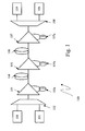
- FIG. 1 schematically shows a WDM transmission system 100 using the compensating spools solution.
- transmitters 101 coupled to a multiplexer 102 are shown at the transmission side and receivers 109 coupled to a de-multiplexer 108 are shown at the receiving side.
- the optical transmission line is represented by reference numerals 104 and 106.
- the optical signal generated at the transmission side is output from the multiplexer 102 and is fed into an optical amplifier 103.
- the optical amplifier 103 is coupled to a spool of fiber 103a which has partly opposite dispersion characteristics as compared to those of the optical transmission line 104, therefore partial dispersion compensation is provided by the spool of fiber 103a.
- this dispersion compensation is provided at the starting point of the transmission, it is usually referred to as pre-compensation.
- a similar dispersion compensation is provided in one or more intermediate points of the transmission system, generally referred to as in-line compensation. This is represented in the figure by the optical amplifier 105 and the spool fiber 105a which has dispersion characteristics opposite to those of the transmission line fiber 104.
- another similar compensation is provided at the reception point of the transmission line. This is represented by the optical amplifier 107 and the spool of fiber 107a. This compensation is referred to as post-compensation.
- TDCM Tunable Dispersion Compensating Module
- BER Bit Error Ratio
- FEC Forward Error Correction
- optical compensation can be replaced or enhanced with electrical compensation within the receiver (e.g. adaptive receiver).
- the above solution provides satisfactory results in eliminating the difference of cumulated dispersion between two channels having different wavelengths.
- it contributes to reducing the need for a perfect in-line compensation, which is very difficult or in cases even impossible for some fiber types, especially for G.653 or G.655 types.
- the above solution also provides certain improvement in compensation when a change occurs in the level of the signal within the system; for example after adding or dropping of channels or when the power of an amplifier is changed.
- the above solution is not suitable for the case of Raman distributed systems with co-pumping.
- Raman distributed co-pumping is a widely used technique in order to increase the power of an incoming optical signal. A high-power optical beam is pumped into the transmission fiber in the same direction of propagation as that of the optical signal whereby the signal is amplified as a result of interactions between the fiber material and the pump photons.
- the channel power depends on the Raman gain, therefore the dispersion mapping should be modified when the Raman gain is changed.
- US2004091205 describes a method, apparatus and system for controlling power transients in a Raman-amplified optical transmission system which sin response to the detection of a power transient in an optical signal, varies the gain of at least one dispersion compensating module (DCM) in the Raman-amplified optical transmission system to correct for a change in signal power caused by the power transient.
- DCM dispersion compensating module
- US 20020159131 discloses a dispersion-compensating fiber amplifier having a Raman pumped dispersion-compensating fiber and a distributed optical amplifier.
- the dispersion-compensating fiber is pumped such that the noise contribution of the dispersion-compensating fiber is reduced.
- DCF dispersion compensating fibre
- a polarization combined four channel wavelength division multiplexing 14 xxnm laser diode unit is used for the pumping light source. Losses in the DCF are completely compensated for by means of the Raman gain over 50 nm bandwidth within ⁇ 0.5 dB variation.
- the solution of the invention is implemented in systems where Raman distributed co-pumping is used.
- the invention may be equally applicable where Raman counter-pumping is used over short spans for which a typical application is in very long-haul terrestrial or submarine repeatered applications.
- the Raman pumping may also increase the signal power up to levels close to the non-linear effect limit.
- one object of the present invention is that of providing a dispersion compensation tuning arrangement for an optical transmission system as described in claim 1.
- Another object of the present invention is that of providing an optical transmission system comprising a dispersion compensation arrangement of the invention.
- a further object of the present invention is that of providing a method of tuning dispersion compensation for an optical transmission system as described in claim 6.
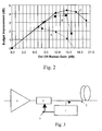
- Figure 2 shows an experimental graph of performance improvement obtained by Raman distributed co-pumping versus the on/off Raman gain for a single span system at 10Gb/s over a single mode fiber (SMF).
- SMF single mode fiber
- the X axis represents Raman gain in dB and the Y axis represents the budget improvement - also in dB - with respect to a configuration without Raman co-pumping.
- the dotted line A (shown for comparison purposes) corresponds to an experimental result where Raman co-pumping is used but pre-compensation is absent. It is to be noted that for single-span systems without using Raman co-pumping the performance of the system is usually optimal when there is no pre-compensation.
- the broken line B corresponds to a -1023ps/nm pre-compensation level and the solid line C represents a performance obtained by -505ps/nm pre-compensation level with Raman co-pumping present in both cases.
- lines A, B and C represent optimal results in each case in the sense that, the Raman gain and the pre-compensation being fixed for each measurement point, the signal power is adjusted to get the best performance.
- the solution proposed by the present invention aims in general terms, at controlling the level of pre-compensation on the optical signal when Raman co-pumping is used. This is done with due regard to the fact that in systems using Raman distributed co-pumping, the channel power depends on the Raman gain, therefore the dispersion mapping should be modified when the Raman gain is changed.
- the invention proposes the use of a TDCM at a pre-compensation stage and to control its response in dependence on the Raman gain in order to set a pre-compensation value that depends on the on/off Raman gain, and hence on the Raman pump power.
- Figure 3 shows a schematic block diagram representation of a dispersion compensation arrangement with Raman co-pumping based on the principles of the present invention.
- a Raman pump 1 is coupled to an optical transmission line 2 and is adapted for co-pumping optical signal power into the optical transmission line 2.
- the Raman pump 1 is further coupled, through a control loop 3 to a TDCM 4.
- the TDCM 4 is located at or close to the transmitting end (the latter not shown in the figure) of the optical transmission line and is in charge of performing tuned pre-compensation on the optical signal to be transmitted.
- an optical amplifier 5 is shown upstream of the TDCM 4.
- the optical amplifier 5, as is known, is in charge of amplifying the optical signal before pre-compensation at the TDCM 4.
- An example of such optical amplifier is an erbium doped amplifier.
- the use of the optical amplifier 5 is optional.
- the pre-compensation level may first be set at a given value and then this value may be dynamically controlled in order to avoid performance degradation over the system life.
- this value may be dynamically controlled in order to avoid performance degradation over the system life.
- dynamic control may make it possible to overcome, or reduce the influence of, any fluctuation in the pump power caused by the ageing of the pump in the Raman pump assembly, or similarly in the ageing of the optional erbium doped amplifier 5.
Landscapes
- Physics & Mathematics (AREA)
- Electromagnetism (AREA)
- Engineering & Computer Science (AREA)
- Computer Networks & Wireless Communication (AREA)
- Signal Processing (AREA)
- Optical Communication System (AREA)
Claims (12)
- Agencement de réglage à compensation de dispersion pour un système de transmission optique comprenant une configuration WDM et possédant une ligne de transmission optique (2), l'agencement comprenant un module à compensation de dispersion accordable (4) et au moins un amplificateur Raman distribué comprenant une pompe Raman (1) couplée à la ligne de transmission (2), caractérisé en ce que le module à compensation de dispersion (4) est situé sur ou sensiblement proche d'une extrémité de transmission de la ligne de transmission optique (2) et en ce qu'une réponse dudit module à compensation de dispersion accordable (4) est commandée au moyen d'un signal dérivé depuis la pompe Raman (1), ledit signal indicatif d'une puissance de signal d'un signal généré par la pompe Raman, et dans lequel la pompe Raman (1) est couplée via une boucle de commande (3) au module à compensation de dispersion accordable (4), ladite boucle de commande (3) étant disposée en une configuration de rétroaction entre le module à compensation de dispersion accordable (4) et la pompe Raman (1).
- Agencement de réglage à compensation de dispersion selon la revendication précédente, dans lequel la pompe Raman (1) est disposée en une configuration de co-pompage par rapport à la ligne de transmission optique (2).
- de réglage à de dispersion selon l'une des revendications précédentes, dans lequel la pompe Raman (1) est en une configuration de contre-pompage par rapport à la de transmission optique (2).
- Agencement de réglage à compensation de dispersion selon l'une des revendications précédentes, dans lequel un amplificateur optique (6) est en amant du module à compensation de dispersion accordable (4).
- de transmission optique un agencement à compensation de dispersion selon l'une quelconque des revendications 1 à 4.
- de réglage à compensation de dispersion pour un système de transmission optique comprenant une configuration WDM et possédant une ligne de transmission optique (2), comprenant un module à compensation de dispersion accordable (4) et au moins un amplificateur Raman distribué comprenant une pompe Raman (1) couplée à la ligne de transmission (2), caractérisé par les étapes de positionnement du module à compensation de dispersion (4) sur ou sensiblement proche d'une extrémité due transmission de la ligne de transmission optique (2), d'obtention signal indicatif d'une puissance de signal d'un signal généré par la pompe Raman, et de contrôle d'une réponse dudit module à compensation de dispersion accordable (4) au moyen d'un signal dérivé la pompe Raman (1), lequel la pompe Raman (1) est couplée via une boucle de commande (3) au module à compensation de dispersion accordable (4), ladite boucle de commande (3) étant disposée en une configuration de rétroaction entre le module à compensation de dispersion accordable (4) et la pompe Raman (1).
- Procédé de réglage à compensation de dispersion selon la revendication 6, dans lequel la pompe Raman (1) effectue le co-pompage du signal optique par rapport à la ligne de transmission optique (2).
- Procédé de réglage à compensation de dispersion selon la revendication 6, dans lequel la pompe Raman (1) effectue le contre-pompage du signal optique par rapport à la ligne de transmission optique (2).
- Procédé de réglage à compensation de dispersion selon l'une quelconque des revendications 5 à 8, dans lequel le contrôle de la réponse du module à compensation de dispersion accordable est pour surmonter les fluctuations dans la puissance de la pompe Raman (1).
- Procédé de réglage à compensation de dispersion selon l'une quelconque des revendications 5 à 9, dans lequel le contrôle de la réponse du module à compensation de dispersion accordable est utilisé pour surmonter les effets du changement dans la puissance du signal.
- Procédé régalage à compensation de dispersion selon l'une quelconque des revendications 5 à 10, dans lequel un point de réglage du niveau de compensation de dispersion est choisi on fonction de critères préétablis.
- Procédé de réglage à compensation de dispersion selon la revendication 11, dans lequel le point de réglage du niveau de compensation de dispersion est choisi dans une table consultation prédéfinie.
Priority Applications (5)
| Application Number | Priority Date | Filing Date | Title |
|---|---|---|---|
| AT05301084T ATE470281T1 (de) | 2005-12-20 | 2005-12-20 | Vorrichtung und verfahren zur automatischen abstimmung einer farbzerstreuungskompensation für wdm übertragungssysteme unter verwendung einer verteilten raman co-pumpe |
| EP05301084A EP1802006B1 (fr) | 2005-12-20 | 2005-12-20 | Système et méthode pour le réglage automatique de la dispersion chromatique d'un système de transmission WDM qui utilise Raman distribué à co-pompage |
| DE602005021666T DE602005021666D1 (de) | 2005-12-20 | 2005-12-20 | Vorrichtung und Verfahren zur automatischen Abstimmung einer Farbzerstreuungskompensation für WDM Übertragungssysteme unter Verwendung einer verteilten Raman Co-Pumpe |
| CN200610168741.6A CN1992563B (zh) | 2005-12-20 | 2006-12-19 | 为波分复用传输系统自动调整色散补偿的设备、系统和方法 |
| US11/612,680 US7751720B2 (en) | 2005-12-20 | 2006-12-19 | System and method for automatic tuning of chromatic dispersion compensation for a WDM transmission system using raman distributed co-pumping |
Applications Claiming Priority (1)
| Application Number | Priority Date | Filing Date | Title |
|---|---|---|---|
| EP05301084A EP1802006B1 (fr) | 2005-12-20 | 2005-12-20 | Système et méthode pour le réglage automatique de la dispersion chromatique d'un système de transmission WDM qui utilise Raman distribué à co-pompage |
Publications (2)
| Publication Number | Publication Date |
|---|---|
| EP1802006A1 EP1802006A1 (fr) | 2007-06-27 |
| EP1802006B1 true EP1802006B1 (fr) | 2010-06-02 |
Family
ID=36425273
Family Applications (1)
| Application Number | Title | Priority Date | Filing Date |
|---|---|---|---|
| EP05301084A Expired - Lifetime EP1802006B1 (fr) | 2005-12-20 | 2005-12-20 | Système et méthode pour le réglage automatique de la dispersion chromatique d'un système de transmission WDM qui utilise Raman distribué à co-pompage |
Country Status (5)
| Country | Link |
|---|---|
| US (1) | US7751720B2 (fr) |
| EP (1) | EP1802006B1 (fr) |
| CN (1) | CN1992563B (fr) |
| AT (1) | ATE470281T1 (fr) |
| DE (1) | DE602005021666D1 (fr) |
Families Citing this family (5)
| Publication number | Priority date | Publication date | Assignee | Title |
|---|---|---|---|---|
| CN101207445A (zh) * | 2006-12-21 | 2008-06-25 | 华为技术有限公司 | 一种色散补偿方法和光纤传输系统 |
| IL182937A (en) * | 2007-05-02 | 2011-08-31 | Eci Telecom Ltd | Technique for compensating undesired effects in optical links of an optical communication network |
| WO2011118370A1 (fr) * | 2010-03-26 | 2011-09-29 | 日本電気株式会社 | Dispositif de conversion a/d à procédé à entrelacement dans le temps |
| CN107094049A (zh) * | 2017-04-13 | 2017-08-25 | 中国联合网络通信集团有限公司 | Dd‑pon下行处理的系统和方法 |
| CN111404612B (zh) * | 2020-03-25 | 2021-05-11 | 武汉光谷信息光电子创新中心有限公司 | 光信号放大装置和传输系统 |
Family Cites Families (5)
| Publication number | Priority date | Publication date | Assignee | Title |
|---|---|---|---|---|
| US6657774B1 (en) * | 2000-08-18 | 2003-12-02 | Corning Incorporated | Amplifier system with distributed and discrete Raman fiber amplifiers |
| US6529315B2 (en) * | 2001-04-27 | 2003-03-04 | Sycamore Networks, Inc | Optical amplifier providing dispersion compensation |
| US6985284B2 (en) | 2002-11-12 | 2006-01-10 | Lucent Technologies Inc. | Method, apparatus and system for controlling power transients in a Raman-amplified optical transmission system |
| US20040156038A1 (en) * | 2003-02-12 | 2004-08-12 | Xiang-Dong Cao | Method and apparatus for providing real-time chromatic dispersion measurement |
| US7038843B2 (en) * | 2003-08-21 | 2006-05-02 | Lucent Technologies Inc. | Method and system for reducing Raman gain tilt error |
-
2005
- 2005-12-20 AT AT05301084T patent/ATE470281T1/de not_active IP Right Cessation
- 2005-12-20 DE DE602005021666T patent/DE602005021666D1/de not_active Expired - Lifetime
- 2005-12-20 EP EP05301084A patent/EP1802006B1/fr not_active Expired - Lifetime
-
2006
- 2006-12-19 US US11/612,680 patent/US7751720B2/en not_active Expired - Fee Related
- 2006-12-19 CN CN200610168741.6A patent/CN1992563B/zh not_active Expired - Fee Related
Also Published As
| Publication number | Publication date |
|---|---|
| US7751720B2 (en) | 2010-07-06 |
| ATE470281T1 (de) | 2010-06-15 |
| DE602005021666D1 (de) | 2010-07-15 |
| EP1802006A1 (fr) | 2007-06-27 |
| CN1992563A (zh) | 2007-07-04 |
| US20070237526A1 (en) | 2007-10-11 |
| CN1992563B (zh) | 2012-06-06 |
Similar Documents
| Publication | Publication Date | Title |
|---|---|---|
| Sun et al. | Optical fiber amplifiers for WDM optical networks | |
| US6738584B1 (en) | Method for optical fiber communication, and terminal device and system for use in carrying out the method | |
| US6038356A (en) | Lightwave transmission system employing raman and rare-earth doped fiber amplification | |
| US6785042B1 (en) | Slope control of gain wavelength of raman amplification | |
| US6288836B1 (en) | Optical amplifier and optical communication system having the optical amplifier | |
| US7200333B2 (en) | Optical communication apparatus, system, and method that properly compensate for chromatic dispersion | |
| US20020041432A1 (en) | Wavelength division multiplexing optical amplifier with function of gain-equalizing and optical communication system | |
| EP1094624B1 (fr) | Dispositif d'amplification optique, dispositif d'amplification optique à large bande et système de communication optique | |
| EP0910182A2 (fr) | Dispositif et système de transmission optique | |
| JP2004535073A (ja) | 光増幅器の制御アーキテクチャおよび制御方法 | |
| JP2002164846A (ja) | 光伝送システム | |
| CA2423397A1 (fr) | Systeme d'amplificateur comprenant des amplificateurs a fibre raman discret et distribue | |
| US6147796A (en) | Method for determining transmission parameters for the data channels of a WDM optical communication system | |
| Winzer et al. | 10-Gb/s upgrade of bidirectional CWDM systems using electronic equalization and FEC | |
| US6404527B1 (en) | Method and apparatus for transmitting a response signal from an optical repeater to a terminal requesting status information | |
| US7751720B2 (en) | System and method for automatic tuning of chromatic dispersion compensation for a WDM transmission system using raman distributed co-pumping | |
| US6614586B2 (en) | Methods and systems for high performance, wide bandwidth optical communication systems using Raman amplification | |
| US20030231377A1 (en) | System and method for controlling optical amplifier pumps | |
| US6809857B2 (en) | Optical preamplifier with one amplification unit | |
| CN1240944A (zh) | 光纤通信的方法和供此方法使用的终端装置和系统 | |
| JP3987665B2 (ja) | 光増幅装置および光通信システム | |
| Bigo et al. | 320-Gb/s (32 x 10 Gb/s WDM) transmission over 500 km of conventional single-mode fiber with 125-km amplifier spacing | |
| CN1711707A (zh) | 光学系统 | |
| WO2001020821A1 (fr) | Amplificateur optique et systeme de communication optique a multiplexage en longueur d'onde | |
| JP2008153558A (ja) | 光伝送システム及びその信号スペクトラム補正方法 |
Legal Events
| Date | Code | Title | Description |
|---|---|---|---|
| PUAI | Public reference made under article 153(3) epc to a published international application that has entered the european phase |
Free format text: ORIGINAL CODE: 0009012 |
|
| AK | Designated contracting states |
Kind code of ref document: A1 Designated state(s): AT BE BG CH CY CZ DE DK EE ES FI FR GB GR HU IE IS IT LI LT LU LV MC NL PL PT RO SE SI SK TR |
|
| AX | Request for extension of the european patent |
Extension state: AL BA HR MK YU |
|
| RIN1 | Information on inventor provided before grant (corrected) |
Inventor name: LABRUNIE, LAURENT Inventor name: BRANDON, ERIC Inventor name: BOUSSELET, PHILIPPE |
|
| 17P | Request for examination filed |
Effective date: 20071227 |
|
| AKX | Designation fees paid |
Designated state(s): AT BE BG CH CY CZ DE DK EE ES FI FR GB GR HU IE IS IT LI LT LU LV MC NL PL PT RO SE SI SK TR |
|
| 17Q | First examination report despatched |
Effective date: 20080228 |
|
| GRAP | Despatch of communication of intention to grant a patent |
Free format text: ORIGINAL CODE: EPIDOSNIGR1 |
|
| GRAS | Grant fee paid |
Free format text: ORIGINAL CODE: EPIDOSNIGR3 |
|
| GRAA | (expected) grant |
Free format text: ORIGINAL CODE: 0009210 |
|
| AK | Designated contracting states |
Kind code of ref document: B1 Designated state(s): AT BE BG CH CY CZ DE DK EE ES FI FR GB GR HU IE IS IT LI LT LU LV MC NL PL PT RO SE SI SK TR |
|
| REG | Reference to a national code |
Ref country code: GB Ref legal event code: FG4D |
|
| REG | Reference to a national code |
Ref country code: CH Ref legal event code: EP |
|
| REG | Reference to a national code |
Ref country code: IE Ref legal event code: FG4D |
|
| REF | Corresponds to: |
Ref document number: 602005021666 Country of ref document: DE Date of ref document: 20100715 Kind code of ref document: P |
|
| REG | Reference to a national code |
Ref country code: NL Ref legal event code: VDEP Effective date: 20100602 |
|
| PG25 | Lapsed in a contracting state [announced via postgrant information from national office to epo] |
Ref country code: SE Free format text: LAPSE BECAUSE OF FAILURE TO SUBMIT A TRANSLATION OF THE DESCRIPTION OR TO PAY THE FEE WITHIN THE PRESCRIBED TIME-LIMIT Effective date: 20100602 Ref country code: LT Free format text: LAPSE BECAUSE OF FAILURE TO SUBMIT A TRANSLATION OF THE DESCRIPTION OR TO PAY THE FEE WITHIN THE PRESCRIBED TIME-LIMIT Effective date: 20100602 |
|
| LTIE | Lt: invalidation of european patent or patent extension |
Effective date: 20100602 |
|
| PG25 | Lapsed in a contracting state [announced via postgrant information from national office to epo] |
Ref country code: AT Free format text: LAPSE BECAUSE OF FAILURE TO SUBMIT A TRANSLATION OF THE DESCRIPTION OR TO PAY THE FEE WITHIN THE PRESCRIBED TIME-LIMIT Effective date: 20100602 Ref country code: FI Free format text: LAPSE BECAUSE OF FAILURE TO SUBMIT A TRANSLATION OF THE DESCRIPTION OR TO PAY THE FEE WITHIN THE PRESCRIBED TIME-LIMIT Effective date: 20100602 Ref country code: LV Free format text: LAPSE BECAUSE OF FAILURE TO SUBMIT A TRANSLATION OF THE DESCRIPTION OR TO PAY THE FEE WITHIN THE PRESCRIBED TIME-LIMIT Effective date: 20100602 Ref country code: SI Free format text: LAPSE BECAUSE OF FAILURE TO SUBMIT A TRANSLATION OF THE DESCRIPTION OR TO PAY THE FEE WITHIN THE PRESCRIBED TIME-LIMIT Effective date: 20100602 |
|
| PG25 | Lapsed in a contracting state [announced via postgrant information from national office to epo] |
Ref country code: CY Free format text: LAPSE BECAUSE OF FAILURE TO SUBMIT A TRANSLATION OF THE DESCRIPTION OR TO PAY THE FEE WITHIN THE PRESCRIBED TIME-LIMIT Effective date: 20100602 Ref country code: PL Free format text: LAPSE BECAUSE OF FAILURE TO SUBMIT A TRANSLATION OF THE DESCRIPTION OR TO PAY THE FEE WITHIN THE PRESCRIBED TIME-LIMIT Effective date: 20100602 Ref country code: GR Free format text: LAPSE BECAUSE OF FAILURE TO SUBMIT A TRANSLATION OF THE DESCRIPTION OR TO PAY THE FEE WITHIN THE PRESCRIBED TIME-LIMIT Effective date: 20100903 |
|
| PG25 | Lapsed in a contracting state [announced via postgrant information from national office to epo] |
Ref country code: EE Free format text: LAPSE BECAUSE OF FAILURE TO SUBMIT A TRANSLATION OF THE DESCRIPTION OR TO PAY THE FEE WITHIN THE PRESCRIBED TIME-LIMIT Effective date: 20100602 Ref country code: NL Free format text: LAPSE BECAUSE OF FAILURE TO SUBMIT A TRANSLATION OF THE DESCRIPTION OR TO PAY THE FEE WITHIN THE PRESCRIBED TIME-LIMIT Effective date: 20100602 |
|
| PG25 | Lapsed in a contracting state [announced via postgrant information from national office to epo] |
Ref country code: SK Free format text: LAPSE BECAUSE OF FAILURE TO SUBMIT A TRANSLATION OF THE DESCRIPTION OR TO PAY THE FEE WITHIN THE PRESCRIBED TIME-LIMIT Effective date: 20100602 Ref country code: IS Free format text: LAPSE BECAUSE OF FAILURE TO SUBMIT A TRANSLATION OF THE DESCRIPTION OR TO PAY THE FEE WITHIN THE PRESCRIBED TIME-LIMIT Effective date: 20101002 Ref country code: PT Free format text: LAPSE BECAUSE OF FAILURE TO SUBMIT A TRANSLATION OF THE DESCRIPTION OR TO PAY THE FEE WITHIN THE PRESCRIBED TIME-LIMIT Effective date: 20101004 Ref country code: RO Free format text: LAPSE BECAUSE OF FAILURE TO SUBMIT A TRANSLATION OF THE DESCRIPTION OR TO PAY THE FEE WITHIN THE PRESCRIBED TIME-LIMIT Effective date: 20100602 Ref country code: CZ Free format text: LAPSE BECAUSE OF FAILURE TO SUBMIT A TRANSLATION OF THE DESCRIPTION OR TO PAY THE FEE WITHIN THE PRESCRIBED TIME-LIMIT Effective date: 20100602 Ref country code: BE Free format text: LAPSE BECAUSE OF FAILURE TO SUBMIT A TRANSLATION OF THE DESCRIPTION OR TO PAY THE FEE WITHIN THE PRESCRIBED TIME-LIMIT Effective date: 20100602 |
|
| PG25 | Lapsed in a contracting state [announced via postgrant information from national office to epo] |
Ref country code: IT Free format text: LAPSE BECAUSE OF FAILURE TO SUBMIT A TRANSLATION OF THE DESCRIPTION OR TO PAY THE FEE WITHIN THE PRESCRIBED TIME-LIMIT Effective date: 20100602 |
|
| PLBE | No opposition filed within time limit |
Free format text: ORIGINAL CODE: 0009261 |
|
| STAA | Information on the status of an ep patent application or granted ep patent |
Free format text: STATUS: NO OPPOSITION FILED WITHIN TIME LIMIT |
|
| PG25 | Lapsed in a contracting state [announced via postgrant information from national office to epo] |
Ref country code: DK Free format text: LAPSE BECAUSE OF FAILURE TO SUBMIT A TRANSLATION OF THE DESCRIPTION OR TO PAY THE FEE WITHIN THE PRESCRIBED TIME-LIMIT Effective date: 20100602 |
|
| 26N | No opposition filed |
Effective date: 20110303 |
|
| REG | Reference to a national code |
Ref country code: DE Ref legal event code: R097 Ref document number: 602005021666 Country of ref document: DE Effective date: 20110302 |
|
| PG25 | Lapsed in a contracting state [announced via postgrant information from national office to epo] |
Ref country code: MC Free format text: LAPSE BECAUSE OF NON-PAYMENT OF DUE FEES Effective date: 20101231 |
|
| REG | Reference to a national code |
Ref country code: CH Ref legal event code: PL |
|
| PG25 | Lapsed in a contracting state [announced via postgrant information from national office to epo] |
Ref country code: LI Free format text: LAPSE BECAUSE OF NON-PAYMENT OF DUE FEES Effective date: 20101231 Ref country code: IE Free format text: LAPSE BECAUSE OF NON-PAYMENT OF DUE FEES Effective date: 20101220 Ref country code: CH Free format text: LAPSE BECAUSE OF NON-PAYMENT OF DUE FEES Effective date: 20101231 |
|
| PG25 | Lapsed in a contracting state [announced via postgrant information from national office to epo] |
Ref country code: LU Free format text: LAPSE BECAUSE OF NON-PAYMENT OF DUE FEES Effective date: 20101220 Ref country code: HU Free format text: LAPSE BECAUSE OF FAILURE TO SUBMIT A TRANSLATION OF THE DESCRIPTION OR TO PAY THE FEE WITHIN THE PRESCRIBED TIME-LIMIT Effective date: 20101203 Ref country code: BG Free format text: LAPSE BECAUSE OF FAILURE TO SUBMIT A TRANSLATION OF THE DESCRIPTION OR TO PAY THE FEE WITHIN THE PRESCRIBED TIME-LIMIT Effective date: 20100602 |
|
| PG25 | Lapsed in a contracting state [announced via postgrant information from national office to epo] |
Ref country code: TR Free format text: LAPSE BECAUSE OF FAILURE TO SUBMIT A TRANSLATION OF THE DESCRIPTION OR TO PAY THE FEE WITHIN THE PRESCRIBED TIME-LIMIT Effective date: 20100602 |
|
| PG25 | Lapsed in a contracting state [announced via postgrant information from national office to epo] |
Ref country code: BG Free format text: LAPSE BECAUSE OF FAILURE TO SUBMIT A TRANSLATION OF THE DESCRIPTION OR TO PAY THE FEE WITHIN THE PRESCRIBED TIME-LIMIT Effective date: 20100902 |
|
| PG25 | Lapsed in a contracting state [announced via postgrant information from national office to epo] |
Ref country code: ES Free format text: LAPSE BECAUSE OF FAILURE TO SUBMIT A TRANSLATION OF THE DESCRIPTION OR TO PAY THE FEE WITHIN THE PRESCRIBED TIME-LIMIT Effective date: 20100913 |
|
| REG | Reference to a national code |
Ref country code: FR Ref legal event code: GC Effective date: 20131018 |
|
| REG | Reference to a national code |
Ref country code: FR Ref legal event code: CA Effective date: 20150521 |
|
| REG | Reference to a national code |
Ref country code: FR Ref legal event code: CA Effective date: 20150521 |
|
| REG | Reference to a national code |
Ref country code: FR Ref legal event code: PLFP Year of fee payment: 11 |
|
| REG | Reference to a national code |
Ref country code: FR Ref legal event code: PLFP Year of fee payment: 12 |
|
| PGFP | Annual fee paid to national office [announced via postgrant information from national office to epo] |
Ref country code: FR Payment date: 20161222 Year of fee payment: 12 |
|
| PGFP | Annual fee paid to national office [announced via postgrant information from national office to epo] |
Ref country code: DE Payment date: 20171211 Year of fee payment: 13 |
|
| PGFP | Annual fee paid to national office [announced via postgrant information from national office to epo] |
Ref country code: GB Payment date: 20171221 Year of fee payment: 13 |
|
| REG | Reference to a national code |
Ref country code: FR Ref legal event code: ST Effective date: 20180831 |
|
| PG25 | Lapsed in a contracting state [announced via postgrant information from national office to epo] |
Ref country code: FR Free format text: LAPSE BECAUSE OF NON-PAYMENT OF DUE FEES Effective date: 20180102 |
|
| REG | Reference to a national code |
Ref country code: GB Ref legal event code: 732E Free format text: REGISTERED BETWEEN 20190429 AND 20190502 |
|
| REG | Reference to a national code |
Ref country code: DE Ref legal event code: R082 Ref document number: 602005021666 Country of ref document: DE Representative=s name: MENZIETTI WETZEL, DE Ref country code: DE Ref legal event code: R081 Ref document number: 602005021666 Country of ref document: DE Owner name: PROVENANCE ASSET GROUP LLC, PITTSFORD, US Free format text: FORMER OWNER: ALCATEL LUCENT, PARIS, FR |
|
| REG | Reference to a national code |
Ref country code: DE Ref legal event code: R119 Ref document number: 602005021666 Country of ref document: DE |
|
| GBPC | Gb: european patent ceased through non-payment of renewal fee |
Effective date: 20181220 |
|
| PG25 | Lapsed in a contracting state [announced via postgrant information from national office to epo] |
Ref country code: DE Free format text: LAPSE BECAUSE OF NON-PAYMENT OF DUE FEES Effective date: 20190702 |
|
| PG25 | Lapsed in a contracting state [announced via postgrant information from national office to epo] |
Ref country code: GB Free format text: LAPSE BECAUSE OF NON-PAYMENT OF DUE FEES Effective date: 20181220 |