EP1802925B1 - Modellvorhersage-gesteuertes kühlsystem - Google Patents
Modellvorhersage-gesteuertes kühlsystem Download PDFInfo
- Publication number
- EP1802925B1 EP1802925B1 EP05786428A EP05786428A EP1802925B1 EP 1802925 B1 EP1802925 B1 EP 1802925B1 EP 05786428 A EP05786428 A EP 05786428A EP 05786428 A EP05786428 A EP 05786428A EP 1802925 B1 EP1802925 B1 EP 1802925B1
- Authority
- EP
- European Patent Office
- Prior art keywords
- capacity
- cooling
- refrigerant
- compressing
- compressor
- Prior art date
- Legal status (The legal status is an assumption and is not a legal conclusion. Google has not performed a legal analysis and makes no representation as to the accuracy of the status listed.)
- Expired - Lifetime
Links
Images

Classifications
-
- F—MECHANICAL ENGINEERING; LIGHTING; HEATING; WEAPONS; BLASTING
- F25—REFRIGERATION OR COOLING; COMBINED HEATING AND REFRIGERATION SYSTEMS; HEAT PUMP SYSTEMS; MANUFACTURE OR STORAGE OF ICE; LIQUEFACTION SOLIDIFICATION OF GASES
- F25B—REFRIGERATION MACHINES, PLANTS OR SYSTEMS; COMBINED HEATING AND REFRIGERATION SYSTEMS; HEAT PUMP SYSTEMS
- F25B49/00—Arrangement or mounting of control or safety devices
- F25B49/02—Arrangement or mounting of control or safety devices for compression type machines, plants or systems
-
- F—MECHANICAL ENGINEERING; LIGHTING; HEATING; WEAPONS; BLASTING
- F25—REFRIGERATION OR COOLING; COMBINED HEATING AND REFRIGERATION SYSTEMS; HEAT PUMP SYSTEMS; MANUFACTURE OR STORAGE OF ICE; LIQUEFACTION SOLIDIFICATION OF GASES
- F25B—REFRIGERATION MACHINES, PLANTS OR SYSTEMS; COMBINED HEATING AND REFRIGERATION SYSTEMS; HEAT PUMP SYSTEMS
- F25B2400/00—Component parts or details not otherwise provided for in this subclass
- F25B2400/07—Details of compressors or related parts
- F25B2400/075—Details of compressors or related parts with parallel compressors
-
- F—MECHANICAL ENGINEERING; LIGHTING; HEATING; WEAPONS; BLASTING
- F25—REFRIGERATION OR COOLING; COMBINED HEATING AND REFRIGERATION SYSTEMS; HEAT PUMP SYSTEMS; MANUFACTURE OR STORAGE OF ICE; LIQUEFACTION SOLIDIFICATION OF GASES
- F25B—REFRIGERATION MACHINES, PLANTS OR SYSTEMS; COMBINED HEATING AND REFRIGERATION SYSTEMS; HEAT PUMP SYSTEMS
- F25B2400/00—Component parts or details not otherwise provided for in this subclass
- F25B2400/22—Refrigeration systems for supermarkets
-
- F—MECHANICAL ENGINEERING; LIGHTING; HEATING; WEAPONS; BLASTING
- F25—REFRIGERATION OR COOLING; COMBINED HEATING AND REFRIGERATION SYSTEMS; HEAT PUMP SYSTEMS; MANUFACTURE OR STORAGE OF ICE; LIQUEFACTION SOLIDIFICATION OF GASES
- F25B—REFRIGERATION MACHINES, PLANTS OR SYSTEMS; COMBINED HEATING AND REFRIGERATION SYSTEMS; HEAT PUMP SYSTEMS
- F25B2500/00—Problems to be solved
- F25B2500/05—Cost reduction
-
- F—MECHANICAL ENGINEERING; LIGHTING; HEATING; WEAPONS; BLASTING
- F25—REFRIGERATION OR COOLING; COMBINED HEATING AND REFRIGERATION SYSTEMS; HEAT PUMP SYSTEMS; MANUFACTURE OR STORAGE OF ICE; LIQUEFACTION SOLIDIFICATION OF GASES
- F25B—REFRIGERATION MACHINES, PLANTS OR SYSTEMS; COMBINED HEATING AND REFRIGERATION SYSTEMS; HEAT PUMP SYSTEMS
- F25B2500/00—Problems to be solved
- F25B2500/19—Calculation of parameters
Definitions
- the invention relates to a refrigeration system e.g. of the kind installed in supermarkets and comprising a plurality of refrigerated display cases or storage rooms, in the following in general referred to as refrigerated spaces.
- the system comprises a closed-loop system for circulation of a refrigerant between a compressing unit, a condenser, and one or more refrigerated spaces with evaporators for evaporation of the refrigerant.
- the invention relates to a system wherein the compressing unit comprises a variable capacity element, e.g. a plurality of standard reciprocating compressors or scroll compressors to provide a variable volumetric compressing capacity for compressing the refrigerant.
- the system provides a cooling capacity to meet a cooling demand to refrigerate the atmosphere of the refrigerated spaces, in the following referred to as the secondary fluid.
- the vapour of evaporated refrigerant is communicated at a suction pressure to an inlet of the compressing unit.
- the invention further relates to a method of controlling a refrigeration system.
- refrigerating systems typically have one single compressing unit with a plurality of compressors working in parallel to provide compressed refrigerant via a condenser to a plurality of refrigerated spaces.
- the refrigerant is evaporated in an evaporator whereby the temperature of the ambience, i.e. the temperature of the secondary fluid, is decreased.
- each of the spaces has separate evaporators with adjustable inlet valves.
- the inlet valve is temperature controlled, i.e. the valve of a refrigerated space opens and closes based on the temperature of the secondary fluid.
- the above-mentioned valve is usually inserted serially with a thermostatic valve which changes the flow rate based on the superheat of the refrigerant at the outlet of the evaporator.
- the thermostatic valve thus ensures that the refrigerant which is released into the evaporator is completely evaporated when it leaves the evaporator.
- vapour of refrigerant from each of the refrigerated spaces is led to an intake of the compressing unit.
- suction pressure generated by the evaporated refrigerant is measured by a pressure gauge. If the suction pressure is high, the evaporation temperature is also high, and the required cooling may not be available. On the contrary, if the suction pressure is low, the efficiency of the compressors is reduced.
- the compressing capacity of the compressing unit i.e. the specific amount of refrigerant which is compressed, is controlled based on the suction pressure. When the pressure reaches an upper level, the compressing capacity is increased by switching on additional compressors, and when the pressure reaches a lower level, the compressing capacity is decreased by switching out additional compressors.
- the compressor capacity is controlled by a PID based structure using the actual suction pressure as feedback.
- the compressor capacity control is divided into two terms, a proportional term and an integral term.
- the proportional part shown as the first part of Equation 1, reacts directly on the actual control error.
- the integral term shown as the last term of Equation 1, reacts on the integral of the control error.
- the integral term is responsible for eliminating steady state errors, and the proportional part reacts on set-point changes and control errors caused by changes in cooling demands.
- the tuning values K p and T i can be used to tune the controller to the system dynamics.
- one further problem related to a PID based controller is that the lower compressor capacity value will produce a small negative control error.
- the negative error causes the integral part to start a compressor whereby the control error becomes slightly positive with a compressor stop as a result.
- the effect can be seen as a limit-cycle on the compressor capacity, even with constant cooling demand.
- a remedy to avoid the limit-cycle can be to introduce a dead-band where the integral part is only updated when the numerical control error is larger than a given value.
- the general problem i.e. that the PID based structure can only react in a causal way, remains.
- control of refrigeration systems is complicated by relatively long time constants. As an example, it takes long time from an evaporator valve is actuated until the temperature in a corresponding refrigerated space is changing, or it takes long time from a cover is removed from a refrigeration display case until the demand for additional cooling capacity is observed. On the other hand, the time it takes from the compressor capacity is changed to the change has an effect on the pressure on the suction side of the compressing unit, is relatively short.
- JP-A-07 269 926 discloses a refrigeration system according to the preamble of claim 1.
- the invention provides a system according to claim 1.
- the invention further facilitates a more economical operation of the system.
- one advantage of the invention could be that it facilitates a non-causal reaction to set-point changes and disturbances.
- a traditional, e.g. PID based, control approach in refrigeration systems reacts on disturbances when they occur
- a system according to the present invention employ estimates of future disturbances to optimize the control action. Hence the controller can react to disturbances before they occur and thereby reduce the effects of the disturbances.
- PID based control could be the ability to compensate for saturations, such as a maximum compressor capacity. If future saturation is predicted, the controller can adjust the pre-saturated control action to compensate for the future saturation. This enables an optimal sequence of control actions, also referred to as a trajectory of actions, taking the saturations into account.
- the refrigerated space may be cooled to a temperature which is lower than an actually desired set-point temperature in order to compensate for a predicted future cooling demand which exceeds the available cooling capacity of the system.
- the cooling capacity may be controlled by controlling the mass flow through the evaporators.
- the compressing capacity could be controlled e.g. in discrete steps by switching a compressor on or off, or the compressing capacity could be controlled by varying the displacement performed by the compressing unit(s), e.g. by varying the rotational speed of a piston or scroll compressor.
- the mass flow could be varied via an inlet valve controlling the flow through the evaporator.
- the flow of the refrigerant is preferably controlled to achieve a minimum superheat region.
- a thermostatic expansion valve or an electronically controlled valve is inserted e.g. in an inlet of the evaporator.
- the evaporator will produce the maximum cooling capacity for the given operation condition.
- the temperature of the secondary fluid of the refrigerated space is controlled e.g. by a hysteresis control which switches said filling control on and off to keep the air temperature within the desired temperature band.
- the cooling capacity depends on the temperature difference between the evaporating temperature and the temperature of the secondary fluid.
- the compressor control affects the operation conditions by controlling the suction pressure to achieve a desired evaporation temperature.
- the objective of the compressor control is to achieve a suction pressure that produces an evaporating temperature that enables the system to meet the cooling demands. If the evaporating temperature is too close to the temperature of the secondary fluid, the system cannot meet the cooling demand. A too low evaporating temperature is undesirable because the compressor uses more energy than necessary because the pressure difference between the inlet and outlet is increased.
- the estimated future cooling demand could be comprised in a mathematical model which gives the cooling estimate based on a time of the day, or the cooling estimate could be logged in a table, e.g. with corresponding values of time and estimated demand, e.g. for an hour, a day, or a year.
- a prediction of future cooling demands can be established in different ways. Examples are:
- a conventional PID controller detects the rise of the cooling demand and will thus increase the cooling capacity. After the peak, the conventional PID detects the reduction of the cooling demand and therefore reduces the cooling capacity. In the system according to the present invention, the controller will take a future demand into account, and base the cooling capacity on an optimum for the predicted time horizon. Hence, a short peak will typically not cause a change of cooling capacity, but a more permanent change of cooling demand will cause a swift change of capacity to match the demand.
- the control system may have a computer processing unit, CPU, and data storage means to establish a first data set comprising predicted future values of cooling demands and thus demands of compressing capacities, e.g. at different points in time.
- the control system may further contain other sets of data, e.g. in the form of mathematical models or tables from which a specific cooling demand can be derived e.g. based on external operating conditions.
- external conditions may embrace: an outside temperature, a general atmospheric humidity in the environment of the refrigeration system, a number of customers entering the space, e.g. a supermarket, to which the refrigeration system belongs, the arrival of new items to the refrigerated spaces of the supermarket or more simply, the time of the day.
- the first and other data set(s) could be established based on data recorded during previous operation of the system, e.g. data which are logged at specific points in time of the day, e.g. in combination with knowledge about an opening hour of the supermarket, knowledge about a time of arrival of new products for the refrigerated spaces etc. All of these external operating conditions could be logged in a second data set.
- the compressing unit could have any number of compressors of any kind, e.g. reciprocating compressors, rotary compressors, or scroll compressors. One or more of the compressors could have variable speed, and they could be individually turned on and off by the control system.
- the evaporators could be regular evaporators of the kind known from existing display cases in supermarkets. The evaporators have valves which are operated e.g. based on the temperature of the refrigerant when it leaves the evaporator, e.g. a thermostatic expansion valve. The evaporators may also have valves which are operated by a signal from the control system, typically a Pulse Width Modulated (PWM) solenoid valve.
- PWM Pulse Width Modulated
- the cooling capacity depends on the suction pressure, the mass flow of the refrigerant, the evaporation pressure and the condensation pressure.
- future values of the suction pressure in combination with a value of the mass flow can, in one embodiment, express the future values of the cooling demand or it may express required future compressor capacities.
- the suction pressure and the mass flow are therefore the controlled variables. In practice, both of these variables may be varied to obtain a future cooling capacity, or one of the variables may be fixed to a specific value while the other variable is varied to obtain the desired cooling capacity.
- the suction pressure is mentioned as a controlled variable. This is implicitly understood to be with a fixed mass flow, and in any of the examples, the suction pressure may be substituted with the mass flow as the controlled variable.
- a first data set of the controller comprises expected values of suction pressures for different points in time, and the values are determined e.g. based on the previously recorded suction pressures for corresponding external operating conditions.
- the controller may comprise a table with values of outside temperatures, expected arrival of articles for the refrigerated spaces, humidity etc, and corresponding values of suction pressures. From an actually measured external condition and the table, the controller could be capable of predicting a future suction pressure and to control the compressing capacity in accordance therewith.
- the second data set comprises values of cooling capacities or values of suction pressures and mass flow which have previously been recorded at different points in time.
- the CPU can predict future values of cooling demands.
- the suction pressure and mass flow may influence the cooling capacity and may therefore in certain embodiments be used to express the cooling capacity.
- the level of the suction pressure may have caused an increase or a decrease in the compressing capacity. In a system according to the invention, however, an approaching change in the suction pressure may be predicted, and in some cases this change renders the change in capacity unnecessary.
- the controller comprises a cost function that assigns costs to deviation of the controlled variable (suction pressure and/or mass flow) from the set-point. It can also include other entities that need to be considered in an optimal control such as the number of compressor start/stops.
- a prediction horizon is considered, and the horizon is divided into a number of time steps.
- a control action is assigned to each time step and a cost value associated with operation of the system according to the control action and within the time step is determined.
- the costs for operating the system in all time steps according to the sequence of control actions are summed up.
- a similar calculation is made with respect to sequences of alternative control actions, and the sequence which gives the lowest costs is selected, and the system is controlled in accordance with the first control action of this sequence of actions. Subsequently, the calculation is repeated for a horizon which is shifted one time step forward.
- the cooling capacity is considered how close the cooling capacity is to the cooling demand, i.e. a difference between the demanded and the achieved cooling capacity is given a cost value, and this cost value is compared with a cost value associated with an attempt to reduce the difference.
- the cooling capacity may be insufficient, but it may be considered too expensive to reach a higher capacity taking a predicted future demand into consideration. This we will be explained in further details later.
- the controller works by identifying a set of compressor capacities that minimizes said cost function using a model of the system, said cooling demand predictions, and actual system measurements.
- the first compressor capacity of the set is used as the control action.
- the procedure is repeated using new system measurement and updated demand predictions.
- Identifying the optimal set of compressor capacities can be achieved using different methods.
- a basic method implements a least square method which solves the unconstraint optimizing problem. It is desirable to include compressor capacity constraints, whereby solutions containing capacities outside the obtainable region (0-100%) can be avoided. Details on the least square methods can be found in "Predictive Control with Constraints" by J.M. Maciejowski, Prentice Hall.
- one embodiment of the invention relates to a system which is adapted to determine:
- the system being further adapted to determine for each of the switching sequences a cooling capacity which is derivable by the switching sequence and a cost value representing the cost of operating the system in accordance with the switching sequence.
- the system may further be adapted to select a cheapest mode of operating the system being the one out of the switching sequences with the lowest cost value.
- the system being further adapted to control the compressing unit in accordance with the cheapest mode of operation, at least for a period of time corresponding to the first time step by controlling the compressing unit to provide the compressing capacity of the first element in the switching with the lowest cost value.
- the procedure can be continued for any number of subsequent time steps, and preferably, the procedure is repeated each time the system has been controlled at least for a period of time corresponding to the first time step.
- the number of M cooling capacities could be grouped into groups of specific ranges of cooling capacities, and for each group, one cheapest mode of operation could be selected e.g. for each time step or for each specific number of time steps. After a number of time steps, the outcome of the described process could be a large number of switching sequences and corresponding cooling capacities.
- grouping this number into a relatively low number of groups, e.g. into 2, 3, 4 or more groups wherein each group comprises cooling capacities within a specific range, and by selecting one single, cheapest, mode of operation for each group, the amount of data for calculating the next time step is reduced to that selected number of groups, and the calculation can thereby be simplified.
- the cost involved with operation of a compressing unit therefore not only depends on the energy which is consumed by the compressor(s) during operation, but it also depends on the number of changes to the compressing capacity. Accordingly, the cost value could comprise not only the costs of operating the compressing unit in accordance with the switching sequences, but also the costs of the switching between the compressing capacities included in the switching sequences.
- the controller calculates a difference between the cooling capacities derived by each of the switching sequences and a predicted cooling demand i.e. what is predicted to be a required cooling capacity at the specific point in time - i.e. after the M time steps. Based on the difference, the controller calculates cost values representing the costs of operating the system with these differences between the required cooling capacity and the capacities derived by the switching sequences. The system includes in theses cost values, values representing the costs of the required switching compressors on or off according to the switching sequences. At the end, the controller controls, at least in the first time step, the compressors in accordance with the sequence giving the lowest costs, i.e. taken the difference and the switching into account.
- the length of the time-steps may be of equal size, e.g. equal to five times a dynamic time constant of a response to the control of the compressing capacity.
- a shorter sampling-step requires more prediction steps to reach the same prediction horizon, and if the sampling-step is selected much longer, the controller will not be able to react to changes as fast.
- the invention provides a method of operating a refrigeration system, according to claim 8.
- the method could further comprise any step corresponding to the features mentioned in connection with the first aspect of the invention.
- the cooling demand varies significantly during operation.
- night covers may shield the refrigerated spaces during closing hours. In this event, the cooling demand is typically reduced.
- the cooling demand is increased when the supermarket opens, and the staff and customers start to move goods into, or out of the refrigerated spaces.
- the cooling demand is significantly increased. Also, since the sensible load is increased by high surrounding temperatures, such high temperatures cause a higher cooling demand. Similarly, a high absolute humidity gives a higher cooling demand because of the increased latent load when some of the cooling is used to condensate the humidity or to build up ice in the evaporator.
- a higher outdoor temperature does not change the cooling demand, but it may increase the condensing temperature. Such an increase may reduce the enthalpy difference in the evaporator, and may reduce the efficiency of the refrigeration system.
- the cooling capacity can be expressed as the product of the enthalpy difference of the refrigerant while passing the evaporator and the mass-flow of the refrigerant through the evaporator. Hence, to maintain a constant cooling capacity, the refrigerant mass flow must be increased to compensate for the decrease of said enthalpy difference.
- Fig. 1 illustrates the effect on the evaporator enthalpy difference when increasing the condenser pressure. It shows that the inlet enthalpy is increased, but the outlet enthalpy is not affected.
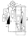
- Fig. 2 shows a refrigeration system, e.g. for a supermarket.
- the system comprises a compressing unit A with a plurality of compressors 1 coupled in parallel between an intake 2 and an outlet 3.
- the compressing capacity of the compressing unit is adjustable. The capacity is adjusted discretely by switching single compressors on or off. In more advanced systems, however, the capacity of single compressors can be adjusted by regulating the compressors speed, e.g. via a frequency converter.
- the outlet manifold is connected to an inlet of a condenser 4 in which the compressed refrigerant is condensed.
- the condenser comprises a condenser control, D, which controls a fan 5 to adjust the heat exchange between the condenser and the surrounding atmosphere.
- the evaporators 6 of a plurality of refrigeration display cases 7 are coupled in parallel to an outlet 8 of the condenser to receive the condensed refrigerant.
- Each refrigeration display case comprises an evaporator and an inlet valve 9 capable of adjusting a flow rate of the condensed refrigerant entering the evaporator.
- the energy which is necessary to evaporate the refrigerant is drawn from the interior, E, of the refrigeration display cases in which the temperatures thereby are reduced. Vapour of refrigerant from each of the refrigeration display cases are collected at the intake 3 of the compressing unit A.
- the control unit F on/off controls the valve to either open or close passage of refrigerant to the evaporator based on the temperature in the display case.
- the control unit G controls the valve based on the superheat of the refrigerant. As an input, the control unit G receives a temperature difference T SH between the evaporation temperature of the refrigerant when it enters the evaporator and the temperature of the refrigerant when it leaves the evaporator.
- suction pressure of the evaporated refrigerant is measured by the pressure gauge, and a pressure signal is communicated to the control unit, C.
- the compressing capacity is controlled to maintain a suction pressure within a certain range, c.f. the previous description of the background of the invention.
- the compressing capacity is increased by switching on additional compressors, and when the pressure reaches a lower level, the compressing capacity is decreased by switching off additional compressors.
- the inlet valves 9 of each of the refrigeration display cases 7 are controlled based on the temperature of the associated refrigeration display cases.
- control unit C is also connected to the inlet valves 9 of the refrigeration display cases 7.
- the control unit comprises a calculating unit and data storage means, and during operation, it is adapted to establish a first data set comprising predicted future values of suction pressures at different points in time.
- the prediction is calculated based on a second data set representing predicted future operating conditions for the refrigeration system.
- the second data set comprises meteorological data, e.g. various temperatures at specific points in time, or the second data set comprises information about an amount of items which in the future will be received in the refrigeration display cases at specific points in time or information about opening hours of the supermarket, at which time isolating hatches of the refrigeration display cases are removed.
- an optimal control sequence can be computed for a specified prediction horizon ( N ). This is done by finding a future control sequence that minimizes the objective function.
- the different objectives for the control can be weighted and thereby taken into account in controlling of the system.
- Tk ⁇ 2 ⁇ Weighed deviation from the wanted suction pressure P suc , ref ... + R ⁇ ⁇ i 1 N ⁇ Cc ⁇ T ⁇ k + i
- the objective is to keep the suction pressure ( P suc ) close to the reference (P suc,ref ) without any large variation in the compressor capacity (Cc) and using only small compressor capacities.
- Other objectives could, however, be taken into account, e.g. by adding more terms in the objective function.
- the mass flow may as previously mentioned be controlled by a valve, and the control of this valve may thus also determine the mass flow when the pressure drop over the valve and the valve characteristics are known. If the system comprises a plurality of refrigerated spaces which are individually fitted with a valve, the mass flows through the valves has to be summed up to achieve the total mass flow in the system.
- Cc is defined in percentage of maximum capacity Cc max of the compressor(s).
- Cc max Maximum capacity of the compressor(s)
- ⁇ vol Volumetric efficiency
- P sl Stroke volume of the compressor
- SH The superheat at the inlet of the compressor
- ⁇ suc Density of the refrigerant at the inlet of the compressor (typically as a function of the suction pressure and the superheat (SH)
- SH , P c and SC are measured at each time step.
- Equation 2 Equation 2 and Equation 3 and assuming SH, P c , and SC are constant, the following can be obtained:
- Q ⁇ act Cc max ⁇ Cc 100 ⁇ ⁇ vol ⁇ V sl ⁇ ⁇ suc P suc ⁇ ⁇ ⁇ h P suc
- Cc is defined in percentage of maximum capacity for the system.
- Equation 1 the objective function (Equation 1) should be minimized under the constraint that Equation 5 is fulfilled:
- Tk ⁇ 2 ... + R ⁇ ⁇ i 1 N ⁇ Cc ⁇ T ⁇ k + i
- P ⁇ ⁇ i 1 N ⁇ Cc ⁇ T ⁇ k + i
Landscapes
- Engineering & Computer Science (AREA)
- Physics & Mathematics (AREA)
- Mechanical Engineering (AREA)
- Thermal Sciences (AREA)
- General Engineering & Computer Science (AREA)
- Devices That Are Associated With Refrigeration Equipment (AREA)
- Radar Systems Or Details Thereof (AREA)
- Feedback Control In General (AREA)
Claims (20)
- Ein Kältesystem mit einem geschlossenen Schleifensystem zur Förderung eines Kältemittels zwischen- einer Verdichtereinheit mit einem variablen Kapazitätselement zur Lieferung einer variablen volumetrischen Verdichtungskapazität zur Verdichtung des Kältemittels, und- mindestens einem Verdampfer zur Verdampfung des verdichteten Kältemittels und damit zur Lieferung einer Kühlkapazität, die den Bedarf an Kühlung für eine Sekundärflüssigkeit eines gekühlten Raumes deckt,- ein Regelsystem wie folgt:- zur Etablierung einer Schätzung des künftigen Kältebedarfes, und- zur Regelung der Kühlkapazität durch Regelung der Verdichtungskapazität zur Anpassung an die Schätzung,dadurch gekennzeichnet, dass das Regelsystem dafür vorgesehen ist, für einen Zeitraum einen Kostenwert zu berechnen, der die Betriebskosten des Systems darstellt, indem es einen Satz von Verdichterkapazitäten identifiziert, der eine Kostenfunktion durch die Anwendung des Folgenden minimiert:- ein Modell des Systems,- genannte Kältebedarfvoraussagen und- aktuelle Systemmessungen.
- Ein System nach Anspruch 1; dadurch gekennzeichnet, dass die erste Verdichterkapazität aus dem Satz von Verdichterkapazitäten als Regelaktion angewandt wird, und dass das Verfahren in einer folgenden Zeitstufe mit einer neuen Systemmessung und ajourgeführten Bedarfsvoraussagen wiederholt wird.
- Ein System nach Anspruch 1 oder 2, dadurch gekennzeichnet, dass die Kältekapazität durch Regelung eines Massendurchflusses vom Kältemittel durch den Verdampfer geregelt wird.
- Ein System nach jedem der vorhergehenden Ansprüche, dadurch gekennzeichnet, dass die Verdichtungskapazität in diskreten Stufen geregelt wird.
- Ein System nach Anspruch 1, dadurch gekennzeichnet, dass die Regelung der Verdichtungskapazitäten auf den Kostenwert basiert.
- Ein System nach jedem der vorhergehenden Ansprüche, dadurch gekennzeichnet, dass das Regelsystem ein Datensatz umfasst, der zukünftige externe Betriebsbedingungen darstellt, und dass das Regelsystem zur Feststellung der Schätzung des zukünftigen Kältebedarfs auf Grund der externen Betriebsbedingungen vorgesehen ist.
- Ein System nach Anspruch 6, dadurch gekennzeichnet, dass externe Betriebsbedingungen und entsprechende Kältebedarfe während des Betriebes aufgezeichnet werden.
- Ein Verfahren zur Regelung eines Kältesystems mit einem geschlossenen Schleifensystem zur Förderung eines Kältemittels zwischen:- eine Verdichtereinheit mit einer variablen Verdichterkapazität zur Verdichtung des Kältemittels, und- mindestens einem Verdampfer zur Verdampfung des Kältemittels,
wobei das Verfahren die folgenden Stufen umfasst:- Schätzung des zukünftigen Kältebedarfes, und- Regelung der Kühlkapazität um diese der Schätzung anzupassen,dadurch gekennzeichnet, dass die Stufen zur Regelung der Kühlkapazität Folgendes umfasst:- innerhalb eines Zeitraumes eine Kostenfunktion für eine Reihe von Bahnen von Sequenzen von möglichen Verdichterkapazitäten innerhalb des Zeitraumes,- aus den Bahnen eine Bahn mit einem niedrigsten Kostenwert auswählen,
Wahl einer Anfangskältekapazität aus der gewählten Bahn und Regelung der Verdichtereinheit oder des Massedurchflusses vom Kältemittel zur Lieferung dieser Kapazität. - Ein Verfahren nach Anspruch 8, dadurch gekennzeichnet, dass der geschätzte künftige Kältebedarf in mindestens einem mathematischen Modell oder einer Tabelle enthalten ist.
- Ein Verfahren nach den Ansprüchen 8-9, dadurch gekennzeichnet, dass die Kühlkapazität durch Regelung der Verdichtungskapazität geregelt wird.
- Ein Verfahren nach den Ansprüchen 8-10, dadurch gekennzeichnet, dass die Kühlkapazität durch Regelung eines Massendurchflusses des Kältemittels durch den Verdampfer geregelt wird.
- Ein Verfahren nach Anspruch 8, dadurch gekennzeichnet, dass der Kostenwert von einem vorausgesagten Kältebedarf und einer geschätzten Kühlkapazität abhängt,
- Ein Verfahren nach Anspruch 12, dadurch gekennzeichnet, dass der Kostenwert außerdem von einer Reihe von Änderungen der Kühlkapazität innerhalb des Zeitraumes abhängt.
- Ein Verfahren nach den Ansprüchen 8-13, dadurch gekennzeichnet, dass der Kostenwert aus einer Akkumulation von Kostenbeiträgen von Zeitrahmen innerhalb des Zeitraumes zusammengesetzt wird.
- Ein Verfahren nach Anspruch 14, dadurch gekennzeichnet, dass eine Bahn von auf einander folgenden Kühlkapazitäten von jedem der Zeitrahmen auf Grund von Kostenbeiträgen der Zeitrahmen gewählt wird.
- Ein Verfahren nach den Ansprüchen 8-15, dadurch gekennzeichnet, dass die Schätzung als ein Produkt eines Massendurchflusses des Kältemittels durch den Verdampfer und einer Änderung der spezifischen Enthalpie des Kältemittels durch den Verdampfer ausgedrückt wird.
- Ein Verfahren nach Anspruch 16, dadurch gekennzeichnet, dass die Schätzung proportional zum Massendurchfluss ist.
- Ein Verfahren nach den Ansprüchen 16-17, dadurch gekennzeichnet, dass die Schätzung proportional zur Verdichtungskapazität ist.
- Ein Verfahren nach den Ansprüchen 8-18, dadurch gekennzeichnet, dass die Stufen für eine nachfolgende Zeitdauer wiederholt werden.
- Ein Verfahren nach den Ansprüchen 9-19, dadurch gekennzeichnet, dass der Kostenwert aus einer Akkumulation von Kostenbeiträgen von Zeitstufen innerhalb des Zeitraumes zusammengesetzt wird.
Applications Claiming Priority (2)
| Application Number | Priority Date | Filing Date | Title |
|---|---|---|---|
| DKPA200401494 | 2004-09-30 | ||
| PCT/DK2005/000625 WO2006034718A1 (en) | 2004-09-30 | 2005-09-30 | A model prediction controlled refrigeration system |
Publications (2)
| Publication Number | Publication Date |
|---|---|
| EP1802925A1 EP1802925A1 (de) | 2007-07-04 |
| EP1802925B1 true EP1802925B1 (de) | 2009-12-30 |
Family
ID=35469724
Family Applications (1)
| Application Number | Title | Priority Date | Filing Date |
|---|---|---|---|
| EP05786428A Expired - Lifetime EP1802925B1 (de) | 2004-09-30 | 2005-09-30 | Modellvorhersage-gesteuertes kühlsystem |
Country Status (5)
| Country | Link |
|---|---|
| US (1) | US7905103B2 (de) |
| EP (1) | EP1802925B1 (de) |
| AT (1) | ATE453841T1 (de) |
| DE (1) | DE602005018669D1 (de) |
| WO (1) | WO2006034718A1 (de) |
Cited By (1)
| Publication number | Priority date | Publication date | Assignee | Title |
|---|---|---|---|---|
| DE102017115497A1 (de) | 2017-07-11 | 2019-01-17 | Liebherr-Transportation Systems Gmbh & Co. Kg | Kühlsystem mit modellprädiktiver Regelung |
Families Citing this family (77)
| Publication number | Priority date | Publication date | Assignee | Title |
|---|---|---|---|---|
| US7412842B2 (en) | 2004-04-27 | 2008-08-19 | Emerson Climate Technologies, Inc. | Compressor diagnostic and protection system |
| US7275377B2 (en) | 2004-08-11 | 2007-10-02 | Lawrence Kates | Method and apparatus for monitoring refrigerant-cycle systems |
| US7885795B2 (en) | 2005-05-02 | 2011-02-08 | American Power Conversion Corporation | Methods and systems for managing facility power and cooling |
| US7881910B2 (en) | 2005-05-02 | 2011-02-01 | American Power Conversion Corporation | Methods and systems for managing facility power and cooling |
| US7389773B2 (en) | 2005-08-18 | 2008-06-24 | Honeywell International Inc. | Emissions sensors for fuel control in engines |
| US7365973B2 (en) | 2006-01-19 | 2008-04-29 | American Power Conversion Corporation | Cooling system and method |
| US8672732B2 (en) | 2006-01-19 | 2014-03-18 | Schneider Electric It Corporation | Cooling system and method |
| BRPI0601967B1 (pt) * | 2006-06-01 | 2021-03-23 | Embraco Indústria De Compressores E Soluções Em Refrigeração Ltda. | Sistema e método de controle de operação de um sistema de refrigeração |
| US8590325B2 (en) | 2006-07-19 | 2013-11-26 | Emerson Climate Technologies, Inc. | Protection and diagnostic module for a refrigeration system |
| US8327656B2 (en) | 2006-08-15 | 2012-12-11 | American Power Conversion Corporation | Method and apparatus for cooling |
| US9568206B2 (en) | 2006-08-15 | 2017-02-14 | Schneider Electric It Corporation | Method and apparatus for cooling |
| US8322155B2 (en) | 2006-08-15 | 2012-12-04 | American Power Conversion Corporation | Method and apparatus for cooling |
| US20080216494A1 (en) | 2006-09-07 | 2008-09-11 | Pham Hung M | Compressor data module |
| US7681404B2 (en) | 2006-12-18 | 2010-03-23 | American Power Conversion Corporation | Modular ice storage for uninterruptible chilled water |
| US8425287B2 (en) | 2007-01-23 | 2013-04-23 | Schneider Electric It Corporation | In-row air containment and cooling system and method |
| US8973385B2 (en) * | 2007-03-02 | 2015-03-10 | Hill Phoenix, Inc. | Refrigeration system |
| JP5559040B2 (ja) | 2007-05-15 | 2014-07-23 | シュナイダー エレクトリック アイティー コーポレーション | 設備の電力及び冷却を管理するための方法及びシステム |
| US20090030554A1 (en) * | 2007-07-26 | 2009-01-29 | Bean Jr John H | Cooling control device and method |
| US20090037142A1 (en) | 2007-07-30 | 2009-02-05 | Lawrence Kates | Portable method and apparatus for monitoring refrigerant-cycle systems |
| US8393169B2 (en) | 2007-09-19 | 2013-03-12 | Emerson Climate Technologies, Inc. | Refrigeration monitoring system and method |
| US9140728B2 (en) | 2007-11-02 | 2015-09-22 | Emerson Climate Technologies, Inc. | Compressor sensor module |
| US8060290B2 (en) | 2008-07-17 | 2011-11-15 | Honeywell International Inc. | Configurable automotive controller |
| MX2011010112A (es) * | 2009-03-27 | 2012-03-07 | Set Ip Holdings Llc | Extractor de agua y generador de electricidad combinado. |
| US9904331B2 (en) | 2009-04-01 | 2018-02-27 | Schneider Electric It Corporation | Method for computing cooling redundancy at the rack level |
| US8249825B2 (en) | 2009-05-08 | 2012-08-21 | American Power Conversion Corporation | System and method for predicting cooling performance of arrangements of equipment in a data center |
| US8355890B2 (en) | 2009-05-08 | 2013-01-15 | American Power Conversion Corporation | System and method for predicting maximum cooler and rack capacities in a data center |
| US8219362B2 (en) | 2009-05-08 | 2012-07-10 | American Power Conversion Corporation | System and method for arranging equipment in a data center |
| US8620461B2 (en) * | 2009-09-24 | 2013-12-31 | Honeywell International, Inc. | Method and system for updating tuning parameters of a controller |
| EP2496897B1 (de) | 2009-11-03 | 2020-01-01 | Carrier Corporation | Druckspitzenreduzierung für kühlsysteme mit einem mikrokanal-wärmetauscher |
| US20110112814A1 (en) * | 2009-11-11 | 2011-05-12 | Emerson Retail Services, Inc. | Refrigerant leak detection system and method |
| US8504175B2 (en) * | 2010-06-02 | 2013-08-06 | Honeywell International Inc. | Using model predictive control to optimize variable trajectories and system control |
| US8688413B2 (en) | 2010-12-30 | 2014-04-01 | Christopher M. Healey | System and method for sequential placement of cooling resources within data center layouts |
| CA2828740C (en) | 2011-02-28 | 2016-07-05 | Emerson Electric Co. | Residential solutions hvac monitoring and diagnosis |
| US9677493B2 (en) | 2011-09-19 | 2017-06-13 | Honeywell Spol, S.R.O. | Coordinated engine and emissions control system |
| US9650934B2 (en) | 2011-11-04 | 2017-05-16 | Honeywell spol.s.r.o. | Engine and aftertreatment optimization system |
| US20130111905A1 (en) | 2011-11-04 | 2013-05-09 | Honeywell Spol. S.R.O. | Integrated optimization and control of an engine and aftertreatment system |
| AU2011384046A1 (en) | 2011-12-22 | 2014-07-17 | Schneider Electric It Corporation | Analysis of effect of transient events on temperature in a data center |
| CN104137660B (zh) | 2011-12-22 | 2017-11-24 | 施耐德电气It公司 | 用于在电子系统中预测温度值的系统和方法 |
| US8964338B2 (en) | 2012-01-11 | 2015-02-24 | Emerson Climate Technologies, Inc. | System and method for compressor motor protection |
| US9310439B2 (en) | 2012-09-25 | 2016-04-12 | Emerson Climate Technologies, Inc. | Compressor having a control and diagnostic module |
| US20150338137A1 (en) | 2013-01-02 | 2015-11-26 | Danfoss A/S | Method for controlling an integrated cooling and heating facility |
| EP2816301A1 (de) * | 2013-06-18 | 2014-12-24 | Danfoss A/S | Verfahren zur Steuerung einer integrierten Kühl- und Heizeinrichtung |
| US9551504B2 (en) | 2013-03-15 | 2017-01-24 | Emerson Electric Co. | HVAC system remote monitoring and diagnosis |
| CA2904734C (en) | 2013-03-15 | 2018-01-02 | Emerson Electric Co. | Hvac system remote monitoring and diagnosis |
| US9803902B2 (en) | 2013-03-15 | 2017-10-31 | Emerson Climate Technologies, Inc. | System for refrigerant charge verification using two condenser coil temperatures |
| AU2014248049B2 (en) | 2013-04-05 | 2018-06-07 | Emerson Climate Technologies, Inc. | Heat-pump system with refrigerant charge diagnostics |
| GB2521141A (en) * | 2013-12-10 | 2015-06-17 | Jaguar Land Rover Ltd | Method of controlling temperature |
| US9625196B2 (en) | 2014-06-09 | 2017-04-18 | Mitsubishi Electric Research Laboratories, Inc. | System and method for controlling of vapor compression system |
| DE102014013658B4 (de) * | 2014-09-15 | 2020-06-18 | Hoffmeister Leuchten Gmbh | Montagesystem, Befestigungseinrichtung und Verfahren zur Befestigung einer Leuchte und Leuchte mit einer Befestigungseinrichtung |
| EP3051367B1 (de) | 2015-01-28 | 2020-11-25 | Honeywell spol s.r.o. | Ansatz und system zur handhabung von einschränkungen für gemessene störungen mit unsicherer vorschau |
| EP3056706A1 (de) | 2015-02-16 | 2016-08-17 | Honeywell International Inc. | Ansatz zur nachbehandlungssystemmodellierung und modellidentifizierung |
| EP3091212A1 (de) | 2015-05-06 | 2016-11-09 | Honeywell International Inc. | Identifikationsansatz für verbrennungsmotor-mittelwertmodelle |
| US9851727B2 (en) | 2015-05-28 | 2017-12-26 | Carrier Corporation | Coordinated control of HVAC system using aggregated system demand |
| EP3125052B1 (de) | 2015-07-31 | 2020-09-02 | Garrett Transportation I Inc. | Quadratischer programmlöser für mpc mit variabler anordnung |
| US10272779B2 (en) | 2015-08-05 | 2019-04-30 | Garrett Transportation I Inc. | System and approach for dynamic vehicle speed optimization |
| US9920971B2 (en) * | 2015-09-23 | 2018-03-20 | International Business Machines Corporation | Refrigerated transport temperature regulation |
| US20180364658A1 (en) * | 2015-12-18 | 2018-12-20 | Carrier Corporation | Adaptive control of hvac system |
| DE102015016852A1 (de) * | 2015-12-23 | 2017-06-29 | Liebherr-Transportation Systems Gmbh & Co. Kg | Verfahren zur Regelung eines Kühlaggregats mit mehreren Kompressoren und Kühlaggregat |
| US10415492B2 (en) | 2016-01-29 | 2019-09-17 | Garrett Transportation I Inc. | Engine system with inferential sensor |
| US10124750B2 (en) | 2016-04-26 | 2018-11-13 | Honeywell International Inc. | Vehicle security module system |
| US10036338B2 (en) | 2016-04-26 | 2018-07-31 | Honeywell International Inc. | Condition-based powertrain control system |
| US10564612B2 (en) | 2016-06-30 | 2020-02-18 | Johnson Controls Technology Company | Variable refrigerant flow system with multi-level model predictive control |
| US11789415B2 (en) | 2016-06-30 | 2023-10-17 | Johnson Controls Tyco IP Holdings LLP | Building HVAC system with multi-level model predictive control |
| CN109416191B (zh) | 2016-06-30 | 2021-08-17 | 江森自控科技公司 | 具有预测控制的变制冷剂流量系统 |
| US20180004171A1 (en) | 2016-06-30 | 2018-01-04 | Johnson Controls Technology Company | Hvac system using model predictive control with distributed low-level airside optimization and airside power consumption model |
| EP3548729B1 (de) | 2016-11-29 | 2023-02-22 | Garrett Transportation I Inc. | Inferenzflusssensor |
| US10816235B2 (en) | 2017-04-27 | 2020-10-27 | Johnson Controls Technology Company | Building energy system with predictive control of battery and green energy resources |
| MX2019012897A (es) | 2017-05-01 | 2020-02-03 | Danfoss As | Metodo para controlar la presion de succion en funcion de una entidad de refrigeracion mas cargada. |
| US11057213B2 (en) | 2017-10-13 | 2021-07-06 | Garrett Transportation I, Inc. | Authentication system for electronic control unit on a bus |
| DE102018109785A1 (de) * | 2018-04-24 | 2019-10-24 | Vaillant Gmbh | Prädiktive Regelung einer Wärmepumpe |
| US11181316B2 (en) | 2018-05-30 | 2021-11-23 | Lineage Logistics, LLC | Thermal control system |
| CN111692721B (zh) | 2019-03-15 | 2023-09-22 | 开利公司 | 用于空气调节系统的控制方法 |
| US10558937B1 (en) | 2019-04-22 | 2020-02-11 | Lineage Logistics Llc | Scheduled thermal control system |
| US11067325B2 (en) | 2019-06-14 | 2021-07-20 | Hitachi-Johnson Controls Air Conditioning, Inc. | Refrigeration cycle optimization |
| WO2021206632A1 (en) * | 2020-04-06 | 2021-10-14 | Nanyang Technological University | Method and control system for controlling an air-conditioning system |
| FR3132564B1 (fr) | 2022-02-08 | 2024-02-23 | Commissariat Energie Atomique | Procédé de commande du fonctionnement d’une thermofrigopompe |
| CN115562034B (zh) * | 2022-10-20 | 2025-03-28 | 宝鸡雷博精密工业有限责任公司 | 并联冷机系统的负荷分配控制方法、系统、设备及介质 |
Family Cites Families (7)
| Publication number | Priority date | Publication date | Assignee | Title |
|---|---|---|---|---|
| JPS588956A (ja) | 1981-07-10 | 1983-01-19 | 株式会社システム・ホ−ムズ | ヒ−トポンプ式冷暖房装置 |
| JPH05264086A (ja) | 1992-03-19 | 1993-10-12 | Hitachi Ltd | 空気調和装置およびその制御装置 |
| JPH07269926A (ja) * | 1994-02-14 | 1995-10-20 | Daikin Ind Ltd | 空気調和装置の制御装置 |
| US6185483B1 (en) * | 1998-01-27 | 2001-02-06 | Johnson Controls, Inc. | Real-time pricing controller of an energy storage medium |
| US6691526B2 (en) * | 2000-03-09 | 2004-02-17 | Gether As | Method and apparatus for heating and cooling of buildings |
| KR100396849B1 (ko) * | 2001-03-26 | 2003-09-03 | 엘지전자 주식회사 | 멀티 컴프레서가 적용된 공기 조화기의 제어 방법 |
| US7147168B1 (en) * | 2003-08-11 | 2006-12-12 | Halton Company | Zone control of space conditioning system with varied uses |
-
2005
- 2005-09-30 EP EP05786428A patent/EP1802925B1/de not_active Expired - Lifetime
- 2005-09-30 DE DE602005018669T patent/DE602005018669D1/de not_active Expired - Lifetime
- 2005-09-30 AT AT05786428T patent/ATE453841T1/de not_active IP Right Cessation
- 2005-09-30 WO PCT/DK2005/000625 patent/WO2006034718A1/en not_active Ceased
- 2005-09-30 US US11/663,871 patent/US7905103B2/en not_active Expired - Fee Related
Cited By (1)
| Publication number | Priority date | Publication date | Assignee | Title |
|---|---|---|---|---|
| DE102017115497A1 (de) | 2017-07-11 | 2019-01-17 | Liebherr-Transportation Systems Gmbh & Co. Kg | Kühlsystem mit modellprädiktiver Regelung |
Also Published As
| Publication number | Publication date |
|---|---|
| US7905103B2 (en) | 2011-03-15 |
| ATE453841T1 (de) | 2010-01-15 |
| US20080000241A1 (en) | 2008-01-03 |
| DE602005018669D1 (de) | 2010-02-11 |
| WO2006034718A1 (en) | 2006-04-06 |
| EP1802925A1 (de) | 2007-07-04 |
Similar Documents
| Publication | Publication Date | Title |
|---|---|---|
| US7905103B2 (en) | Model prediction controlled refrigeration system | |
| US11493246B2 (en) | Demand flow for air cooled chillers | |
| US10174957B2 (en) | System and method for controlling multi-zone vapor compression systems | |
| EP3465019B1 (de) | System und verfahren zum steuern ein mehrzonen-dampfkompressorsystem und übergangsloses computerlesbares speichermedium | |
| Henze et al. | Guidelines for improved performance of ice storage systems | |
| US9263891B2 (en) | Power saving system and method for a refrigeration system, providing for short term response to reduce ripples on a power grid | |
| US9182154B2 (en) | Adaptive control of vapor compression system | |
| US20200292200A1 (en) | Control method for air conditioning system | |
| US8825184B2 (en) | Multivariable optimization of operation of vapor compression systems | |
| US8996141B1 (en) | Adaptive predictive functional controller | |
| AU2005302419B2 (en) | Condenser fan control system | |
| Elliott et al. | Model-based predictive control of a multi-evaporator vapor compression cooling cycle | |
| Larsen et al. | Supermarket refrigeration system-benchmark for hybrid system control | |
| US10107531B2 (en) | Method for controlling a chiller system | |
| US20120078424A1 (en) | Central cooling and circulation energy management control system | |
| US20210302044A1 (en) | Information processing apparatus and air-conditioning system provided with the same | |
| CN117190409A (zh) | 用于多联机空调制热控制的方法及装置、多联机空调 | |
| Shafiei et al. | A supervisory control approach in economic MPC design for refrigeration systems | |
| US4459818A (en) | Supervisory control of chilled water temperature | |
| EP3124897B1 (de) | Verfahren und vorrichtung zur dampfkompressionsschaltkreissteuerung | |
| EP2000754A2 (de) | Verfahren zur Schätzung der Wärmebelastung einer Leitung für eine Betriebsflüssigkeit am Auslass einer Kühlmaschine | |
| EP2992276A1 (de) | Verfahren zur steuerung eines dampfkompressionssystems, das mit einem intelligenten stromnetz verbunden ist | |
| EP3754269B1 (de) | Verfahren und assoziiertes rechner-speichermedium zur steuerung des abtauzyklus eines dampfkompressionssystems | |
| US7797957B2 (en) | Methods and apparatus for linearized temperature control of commercial refrigeration systems | |
| Larsen et al. | Supermarket refrigeration systems-a benchmark for the optimal control of hybrid systems |
Legal Events
| Date | Code | Title | Description |
|---|---|---|---|
| PUAI | Public reference made under article 153(3) epc to a published international application that has entered the european phase |
Free format text: ORIGINAL CODE: 0009012 |
|
| 17P | Request for examination filed |
Effective date: 20070424 |
|
| AK | Designated contracting states |
Kind code of ref document: A1 Designated state(s): AT BE BG CH CY CZ DE DK EE ES FI FR GB GR HU IE IS IT LI LT LU LV MC NL PL PT RO SE SI SK TR |
|
| DAX | Request for extension of the european patent (deleted) | ||
| 17Q | First examination report despatched |
Effective date: 20090211 |
|
| GRAP | Despatch of communication of intention to grant a patent |
Free format text: ORIGINAL CODE: EPIDOSNIGR1 |
|
| GRAS | Grant fee paid |
Free format text: ORIGINAL CODE: EPIDOSNIGR3 |
|
| GRAA | (expected) grant |
Free format text: ORIGINAL CODE: 0009210 |
|
| AK | Designated contracting states |
Kind code of ref document: B1 Designated state(s): AT BE BG CH CY CZ DE DK EE ES FI FR GB GR HU IE IS IT LI LT LU LV MC NL PL PT RO SE SI SK TR |
|
| REG | Reference to a national code |
Ref country code: GB Ref legal event code: FG4D |
|
| REG | Reference to a national code |
Ref country code: CH Ref legal event code: EP |
|
| REG | Reference to a national code |
Ref country code: IE Ref legal event code: FG4D |
|
| REF | Corresponds to: |
Ref document number: 602005018669 Country of ref document: DE Date of ref document: 20100211 Kind code of ref document: P |
|
| PG25 | Lapsed in a contracting state [announced via postgrant information from national office to epo] |
Ref country code: SE Free format text: LAPSE BECAUSE OF FAILURE TO SUBMIT A TRANSLATION OF THE DESCRIPTION OR TO PAY THE FEE WITHIN THE PRESCRIBED TIME-LIMIT Effective date: 20091230 Ref country code: LT Free format text: LAPSE BECAUSE OF FAILURE TO SUBMIT A TRANSLATION OF THE DESCRIPTION OR TO PAY THE FEE WITHIN THE PRESCRIBED TIME-LIMIT Effective date: 20091230 Ref country code: FI Free format text: LAPSE BECAUSE OF FAILURE TO SUBMIT A TRANSLATION OF THE DESCRIPTION OR TO PAY THE FEE WITHIN THE PRESCRIBED TIME-LIMIT Effective date: 20091230 |
|
| REG | Reference to a national code |
Ref country code: NL Ref legal event code: VDEP Effective date: 20091230 |
|
| LTIE | Lt: invalidation of european patent or patent extension |
Effective date: 20091230 |
|
| PG25 | Lapsed in a contracting state [announced via postgrant information from national office to epo] |
Ref country code: PL Free format text: LAPSE BECAUSE OF FAILURE TO SUBMIT A TRANSLATION OF THE DESCRIPTION OR TO PAY THE FEE WITHIN THE PRESCRIBED TIME-LIMIT Effective date: 20091230 Ref country code: LV Free format text: LAPSE BECAUSE OF FAILURE TO SUBMIT A TRANSLATION OF THE DESCRIPTION OR TO PAY THE FEE WITHIN THE PRESCRIBED TIME-LIMIT Effective date: 20091230 Ref country code: SI Free format text: LAPSE BECAUSE OF FAILURE TO SUBMIT A TRANSLATION OF THE DESCRIPTION OR TO PAY THE FEE WITHIN THE PRESCRIBED TIME-LIMIT Effective date: 20091230 |
|
| PG25 | Lapsed in a contracting state [announced via postgrant information from national office to epo] |
Ref country code: AT Free format text: LAPSE BECAUSE OF FAILURE TO SUBMIT A TRANSLATION OF THE DESCRIPTION OR TO PAY THE FEE WITHIN THE PRESCRIBED TIME-LIMIT Effective date: 20091230 |
|
| PG25 | Lapsed in a contracting state [announced via postgrant information from national office to epo] |
Ref country code: EE Free format text: LAPSE BECAUSE OF FAILURE TO SUBMIT A TRANSLATION OF THE DESCRIPTION OR TO PAY THE FEE WITHIN THE PRESCRIBED TIME-LIMIT Effective date: 20091230 Ref country code: RO Free format text: LAPSE BECAUSE OF FAILURE TO SUBMIT A TRANSLATION OF THE DESCRIPTION OR TO PAY THE FEE WITHIN THE PRESCRIBED TIME-LIMIT Effective date: 20091230 Ref country code: ES Free format text: LAPSE BECAUSE OF FAILURE TO SUBMIT A TRANSLATION OF THE DESCRIPTION OR TO PAY THE FEE WITHIN THE PRESCRIBED TIME-LIMIT Effective date: 20100410 Ref country code: PT Free format text: LAPSE BECAUSE OF FAILURE TO SUBMIT A TRANSLATION OF THE DESCRIPTION OR TO PAY THE FEE WITHIN THE PRESCRIBED TIME-LIMIT Effective date: 20100430 Ref country code: IS Free format text: LAPSE BECAUSE OF FAILURE TO SUBMIT A TRANSLATION OF THE DESCRIPTION OR TO PAY THE FEE WITHIN THE PRESCRIBED TIME-LIMIT Effective date: 20100430 Ref country code: BG Free format text: LAPSE BECAUSE OF FAILURE TO SUBMIT A TRANSLATION OF THE DESCRIPTION OR TO PAY THE FEE WITHIN THE PRESCRIBED TIME-LIMIT Effective date: 20100330 Ref country code: NL Free format text: LAPSE BECAUSE OF FAILURE TO SUBMIT A TRANSLATION OF THE DESCRIPTION OR TO PAY THE FEE WITHIN THE PRESCRIBED TIME-LIMIT Effective date: 20091230 |
|
| PG25 | Lapsed in a contracting state [announced via postgrant information from national office to epo] |
Ref country code: BE Free format text: LAPSE BECAUSE OF FAILURE TO SUBMIT A TRANSLATION OF THE DESCRIPTION OR TO PAY THE FEE WITHIN THE PRESCRIBED TIME-LIMIT Effective date: 20091230 Ref country code: SK Free format text: LAPSE BECAUSE OF FAILURE TO SUBMIT A TRANSLATION OF THE DESCRIPTION OR TO PAY THE FEE WITHIN THE PRESCRIBED TIME-LIMIT Effective date: 20091230 Ref country code: CZ Free format text: LAPSE BECAUSE OF FAILURE TO SUBMIT A TRANSLATION OF THE DESCRIPTION OR TO PAY THE FEE WITHIN THE PRESCRIBED TIME-LIMIT Effective date: 20091230 |
|
| PG25 | Lapsed in a contracting state [announced via postgrant information from national office to epo] |
Ref country code: GR Free format text: LAPSE BECAUSE OF FAILURE TO SUBMIT A TRANSLATION OF THE DESCRIPTION OR TO PAY THE FEE WITHIN THE PRESCRIBED TIME-LIMIT Effective date: 20100331 Ref country code: CY Free format text: LAPSE BECAUSE OF FAILURE TO SUBMIT A TRANSLATION OF THE DESCRIPTION OR TO PAY THE FEE WITHIN THE PRESCRIBED TIME-LIMIT Effective date: 20091230 |
|
| PLBE | No opposition filed within time limit |
Free format text: ORIGINAL CODE: 0009261 |
|
| STAA | Information on the status of an ep patent application or granted ep patent |
Free format text: STATUS: NO OPPOSITION FILED WITHIN TIME LIMIT |
|
| 26N | No opposition filed |
Effective date: 20101001 |
|
| PG25 | Lapsed in a contracting state [announced via postgrant information from national office to epo] |
Ref country code: DK Free format text: LAPSE BECAUSE OF FAILURE TO SUBMIT A TRANSLATION OF THE DESCRIPTION OR TO PAY THE FEE WITHIN THE PRESCRIBED TIME-LIMIT Effective date: 20091230 |
|
| PG25 | Lapsed in a contracting state [announced via postgrant information from national office to epo] |
Ref country code: MC Free format text: LAPSE BECAUSE OF NON-PAYMENT OF DUE FEES Effective date: 20100930 |
|
| REG | Reference to a national code |
Ref country code: CH Ref legal event code: PL |
|
| PG25 | Lapsed in a contracting state [announced via postgrant information from national office to epo] |
Ref country code: CH Free format text: LAPSE BECAUSE OF NON-PAYMENT OF DUE FEES Effective date: 20100930 Ref country code: LI Free format text: LAPSE BECAUSE OF NON-PAYMENT OF DUE FEES Effective date: 20100930 Ref country code: IE Free format text: LAPSE BECAUSE OF NON-PAYMENT OF DUE FEES Effective date: 20100930 |
|
| PG25 | Lapsed in a contracting state [announced via postgrant information from national office to epo] |
Ref country code: HU Free format text: LAPSE BECAUSE OF FAILURE TO SUBMIT A TRANSLATION OF THE DESCRIPTION OR TO PAY THE FEE WITHIN THE PRESCRIBED TIME-LIMIT Effective date: 20100701 Ref country code: LU Free format text: LAPSE BECAUSE OF NON-PAYMENT OF DUE FEES Effective date: 20100930 |
|
| PG25 | Lapsed in a contracting state [announced via postgrant information from national office to epo] |
Ref country code: TR Free format text: LAPSE BECAUSE OF FAILURE TO SUBMIT A TRANSLATION OF THE DESCRIPTION OR TO PAY THE FEE WITHIN THE PRESCRIBED TIME-LIMIT Effective date: 20091230 |
|
| REG | Reference to a national code |
Ref country code: FR Ref legal event code: PLFP Year of fee payment: 11 |
|
| REG | Reference to a national code |
Ref country code: FR Ref legal event code: PLFP Year of fee payment: 12 |
|
| PGFP | Annual fee paid to national office [announced via postgrant information from national office to epo] |
Ref country code: IT Payment date: 20160921 Year of fee payment: 12 Ref country code: GB Payment date: 20160928 Year of fee payment: 12 |
|
| PGFP | Annual fee paid to national office [announced via postgrant information from national office to epo] |
Ref country code: FR Payment date: 20160816 Year of fee payment: 12 |
|
| PGFP | Annual fee paid to national office [announced via postgrant information from national office to epo] |
Ref country code: DE Payment date: 20160927 Year of fee payment: 12 |
|
| REG | Reference to a national code |
Ref country code: DE Ref legal event code: R119 Ref document number: 602005018669 Country of ref document: DE |
|
| GBPC | Gb: european patent ceased through non-payment of renewal fee |
Effective date: 20170930 |
|
| REG | Reference to a national code |
Ref country code: FR Ref legal event code: ST Effective date: 20180531 |
|
| PG25 | Lapsed in a contracting state [announced via postgrant information from national office to epo] |
Ref country code: GB Free format text: LAPSE BECAUSE OF NON-PAYMENT OF DUE FEES Effective date: 20170930 Ref country code: DE Free format text: LAPSE BECAUSE OF NON-PAYMENT OF DUE FEES Effective date: 20180404 |
|
| PG25 | Lapsed in a contracting state [announced via postgrant information from national office to epo] |
Ref country code: FR Free format text: LAPSE BECAUSE OF NON-PAYMENT OF DUE FEES Effective date: 20171002 Ref country code: IT Free format text: LAPSE BECAUSE OF NON-PAYMENT OF DUE FEES Effective date: 20170930 |