EP1802932B1 - Tube en produit metallique profile et procede de production - Google Patents
Tube en produit metallique profile et procede de production Download PDFInfo
- Publication number
- EP1802932B1 EP1802932B1 EP05794807A EP05794807A EP1802932B1 EP 1802932 B1 EP1802932 B1 EP 1802932B1 EP 05794807 A EP05794807 A EP 05794807A EP 05794807 A EP05794807 A EP 05794807A EP 1802932 B1 EP1802932 B1 EP 1802932B1
- Authority
- EP
- European Patent Office
- Prior art keywords
- wall
- ridges
- walls
- brazing
- ridge
- Prior art date
- Legal status (The legal status is an assumption and is not a legal conclusion. Google has not performed a legal analysis and makes no representation as to the accuracy of the status listed.)
- Expired - Lifetime
Links
Images


Classifications
-
- F—MECHANICAL ENGINEERING; LIGHTING; HEATING; WEAPONS; BLASTING
- F28—HEAT EXCHANGE IN GENERAL
- F28F—DETAILS OF HEAT-EXCHANGE AND HEAT-TRANSFER APPARATUS, OF GENERAL APPLICATION
- F28F1/00—Tubular elements; Assemblies of tubular elements
- F28F1/02—Tubular elements of cross-section which is non-circular
- F28F1/022—Tubular elements of cross-section which is non-circular with multiple channels
-
- F—MECHANICAL ENGINEERING; LIGHTING; HEATING; WEAPONS; BLASTING
- F28—HEAT EXCHANGE IN GENERAL
- F28D—HEAT-EXCHANGE APPARATUS, NOT PROVIDED FOR IN ANOTHER SUBCLASS, IN WHICH THE HEAT-EXCHANGE MEDIA DO NOT COME INTO DIRECT CONTACT
- F28D1/00—Heat-exchange apparatus having stationary conduit assemblies for one heat-exchange medium only, the media being in contact with different sides of the conduit wall, in which the other heat-exchange medium is a large body of fluid, e.g. domestic or motor car radiators
- F28D1/02—Heat-exchange apparatus having stationary conduit assemblies for one heat-exchange medium only, the media being in contact with different sides of the conduit wall, in which the other heat-exchange medium is a large body of fluid, e.g. domestic or motor car radiators with heat-exchange conduits immersed in the body of fluid
- F28D1/03—Heat-exchange apparatus having stationary conduit assemblies for one heat-exchange medium only, the media being in contact with different sides of the conduit wall, in which the other heat-exchange medium is a large body of fluid, e.g. domestic or motor car radiators with heat-exchange conduits immersed in the body of fluid with plate-like or laminated conduits
-
- B—PERFORMING OPERATIONS; TRANSPORTING
- B21—MECHANICAL METAL-WORKING WITHOUT ESSENTIALLY REMOVING MATERIAL; PUNCHING METAL
- B21B—ROLLING OF METAL
- B21B1/00—Metal-rolling methods or mills for making semi-finished products of solid or profiled cross-section; Sequence of operations in milling trains; Layout of rolling-mill plant, e.g. grouping of stands; Succession of passes or of sectional pass alternations
- B21B1/22—Metal-rolling methods or mills for making semi-finished products of solid or profiled cross-section; Sequence of operations in milling trains; Layout of rolling-mill plant, e.g. grouping of stands; Succession of passes or of sectional pass alternations for rolling plates, strips, bands or sheets of indefinite length
- B21B1/227—Surface roughening or texturing
-
- B—PERFORMING OPERATIONS; TRANSPORTING
- B21—MECHANICAL METAL-WORKING WITHOUT ESSENTIALLY REMOVING MATERIAL; PUNCHING METAL
- B21C—MANUFACTURE OF METAL SHEETS, WIRE, RODS, TUBES, PROFILES OR LIKE SEMI-MANUFACTURED PRODUCTS OTHERWISE THAN BY ROLLING; AUXILIARY OPERATIONS USED IN CONNECTION WITH METAL-WORKING WITHOUT ESSENTIALLY REMOVING MATERIAL
- B21C37/00—Manufacture of metal sheets, rods, wire, tubes, profiles or like semi-manufactured products, not otherwise provided for; Manufacture of tubes of special shape
- B21C37/06—Manufacture of metal sheets, rods, wire, tubes, profiles or like semi-manufactured products, not otherwise provided for; Manufacture of tubes of special shape of tubes or metal hoses; Combined procedures for making tubes, e.g. for making multi-wall tubes
- B21C37/15—Making tubes of special shape; Making tube fittings
- B21C37/151—Making tubes with multiple passages
-
- F—MECHANICAL ENGINEERING; LIGHTING; HEATING; WEAPONS; BLASTING
- F28—HEAT EXCHANGE IN GENERAL
- F28D—HEAT-EXCHANGE APPARATUS, NOT PROVIDED FOR IN ANOTHER SUBCLASS, IN WHICH THE HEAT-EXCHANGE MEDIA DO NOT COME INTO DIRECT CONTACT
- F28D1/00—Heat-exchange apparatus having stationary conduit assemblies for one heat-exchange medium only, the media being in contact with different sides of the conduit wall, in which the other heat-exchange medium is a large body of fluid, e.g. domestic or motor car radiators
- F28D1/02—Heat-exchange apparatus having stationary conduit assemblies for one heat-exchange medium only, the media being in contact with different sides of the conduit wall, in which the other heat-exchange medium is a large body of fluid, e.g. domestic or motor car radiators with heat-exchange conduits immersed in the body of fluid
- F28D1/03—Heat-exchange apparatus having stationary conduit assemblies for one heat-exchange medium only, the media being in contact with different sides of the conduit wall, in which the other heat-exchange medium is a large body of fluid, e.g. domestic or motor car radiators with heat-exchange conduits immersed in the body of fluid with plate-like or laminated conduits
- F28D1/0391—Heat-exchange apparatus having stationary conduit assemblies for one heat-exchange medium only, the media being in contact with different sides of the conduit wall, in which the other heat-exchange medium is a large body of fluid, e.g. domestic or motor car radiators with heat-exchange conduits immersed in the body of fluid with plate-like or laminated conduits a single plate being bent to form one or more conduits
-
- F—MECHANICAL ENGINEERING; LIGHTING; HEATING; WEAPONS; BLASTING
- F28—HEAT EXCHANGE IN GENERAL
- F28F—DETAILS OF HEAT-EXCHANGE AND HEAT-TRANSFER APPARATUS, OF GENERAL APPLICATION
- F28F1/00—Tubular elements; Assemblies of tubular elements
- F28F1/02—Tubular elements of cross-section which is non-circular
-
- F—MECHANICAL ENGINEERING; LIGHTING; HEATING; WEAPONS; BLASTING
- F28—HEAT EXCHANGE IN GENERAL
- F28F—DETAILS OF HEAT-EXCHANGE AND HEAT-TRANSFER APPARATUS, OF GENERAL APPLICATION
- F28F3/00—Plate-like or laminated elements; Assemblies of plate-like or laminated elements
- F28F3/02—Elements or assemblies thereof with means for increasing heat-transfer area, e.g. with fins, with recesses, with corrugations
- F28F3/04—Elements or assemblies thereof with means for increasing heat-transfer area, e.g. with fins, with recesses, with corrugations the means being integral with the element
-
- B—PERFORMING OPERATIONS; TRANSPORTING
- B21—MECHANICAL METAL-WORKING WITHOUT ESSENTIALLY REMOVING MATERIAL; PUNCHING METAL
- B21B—ROLLING OF METAL
- B21B1/00—Metal-rolling methods or mills for making semi-finished products of solid or profiled cross-section; Sequence of operations in milling trains; Layout of rolling-mill plant, e.g. grouping of stands; Succession of passes or of sectional pass alternations
- B21B1/38—Metal-rolling methods or mills for making semi-finished products of solid or profiled cross-section; Sequence of operations in milling trains; Layout of rolling-mill plant, e.g. grouping of stands; Succession of passes or of sectional pass alternations for rolling sheets of limited length, e.g. folded sheets, superimposed sheets, pack rolling
- B21B2001/383—Cladded or coated products
-
- B—PERFORMING OPERATIONS; TRANSPORTING
- B21—MECHANICAL METAL-WORKING WITHOUT ESSENTIALLY REMOVING MATERIAL; PUNCHING METAL
- B21B—ROLLING OF METAL
- B21B3/00—Rolling materials of special alloys so far as the composition of the alloy requires or permits special rolling methods or sequences ; Rolling of aluminium, copper, zinc or other non-ferrous metals
- B21B2003/001—Aluminium or its alloys
-
- B—PERFORMING OPERATIONS; TRANSPORTING
- B21—MECHANICAL METAL-WORKING WITHOUT ESSENTIALLY REMOVING MATERIAL; PUNCHING METAL
- B21B—ROLLING OF METAL
- B21B27/00—Rolls, roll alloys or roll fabrication; Lubricating, cooling or heating rolls while in use
- B21B27/005—Rolls with a roughened or textured surface; Methods for making same
-
- B—PERFORMING OPERATIONS; TRANSPORTING
- B21—MECHANICAL METAL-WORKING WITHOUT ESSENTIALLY REMOVING MATERIAL; PUNCHING METAL
- B21B—ROLLING OF METAL
- B21B27/00—Rolls, roll alloys or roll fabrication; Lubricating, cooling or heating rolls while in use
- B21B27/02—Shape or construction of rolls
- B21B27/021—Rolls for sheets or strips
-
- F—MECHANICAL ENGINEERING; LIGHTING; HEATING; WEAPONS; BLASTING
- F28—HEAT EXCHANGE IN GENERAL
- F28F—DETAILS OF HEAT-EXCHANGE AND HEAT-TRANSFER APPARATUS, OF GENERAL APPLICATION
- F28F2275/00—Fastening; Joining
- F28F2275/06—Fastening; Joining by welding
- F28F2275/062—Fastening; Joining by welding by impact pressure or friction welding
-
- Y—GENERAL TAGGING OF NEW TECHNOLOGICAL DEVELOPMENTS; GENERAL TAGGING OF CROSS-SECTIONAL TECHNOLOGIES SPANNING OVER SEVERAL SECTIONS OF THE IPC; TECHNICAL SUBJECTS COVERED BY FORMER USPC CROSS-REFERENCE ART COLLECTIONS [XRACs] AND DIGESTS
- Y10—TECHNICAL SUBJECTS COVERED BY FORMER USPC
- Y10T—TECHNICAL SUBJECTS COVERED BY FORMER US CLASSIFICATION
- Y10T29/00—Metal working
- Y10T29/49—Method of mechanical manufacture
- Y10T29/4935—Heat exchanger or boiler making
- Y10T29/49364—Tube joined to flat sheet longitudinally, i.e., tube sheet
-
- Y—GENERAL TAGGING OF NEW TECHNOLOGICAL DEVELOPMENTS; GENERAL TAGGING OF CROSS-SECTIONAL TECHNOLOGIES SPANNING OVER SEVERAL SECTIONS OF THE IPC; TECHNICAL SUBJECTS COVERED BY FORMER USPC CROSS-REFERENCE ART COLLECTIONS [XRACs] AND DIGESTS
- Y10—TECHNICAL SUBJECTS COVERED BY FORMER USPC
- Y10T—TECHNICAL SUBJECTS COVERED BY FORMER US CLASSIFICATION
- Y10T29/00—Metal working
- Y10T29/49—Method of mechanical manufacture
- Y10T29/4935—Heat exchanger or boiler making
- Y10T29/49366—Sheet joined to sheet
-
- Y—GENERAL TAGGING OF NEW TECHNOLOGICAL DEVELOPMENTS; GENERAL TAGGING OF CROSS-SECTIONAL TECHNOLOGIES SPANNING OVER SEVERAL SECTIONS OF THE IPC; TECHNICAL SUBJECTS COVERED BY FORMER USPC CROSS-REFERENCE ART COLLECTIONS [XRACs] AND DIGESTS
- Y10—TECHNICAL SUBJECTS COVERED BY FORMER USPC
- Y10T—TECHNICAL SUBJECTS COVERED BY FORMER US CLASSIFICATION
- Y10T29/00—Metal working
- Y10T29/49—Method of mechanical manufacture
- Y10T29/4935—Heat exchanger or boiler making
- Y10T29/49377—Tube with heat transfer means
- Y10T29/49378—Finned tube
- Y10T29/49382—Helically finned
-
- Y—GENERAL TAGGING OF NEW TECHNOLOGICAL DEVELOPMENTS; GENERAL TAGGING OF CROSS-SECTIONAL TECHNOLOGIES SPANNING OVER SEVERAL SECTIONS OF THE IPC; TECHNICAL SUBJECTS COVERED BY FORMER USPC CROSS-REFERENCE ART COLLECTIONS [XRACs] AND DIGESTS
- Y10—TECHNICAL SUBJECTS COVERED BY FORMER USPC
- Y10T—TECHNICAL SUBJECTS COVERED BY FORMER US CLASSIFICATION
- Y10T29/00—Metal working
- Y10T29/49—Method of mechanical manufacture
- Y10T29/4935—Heat exchanger or boiler making
- Y10T29/49377—Tube with heat transfer means
- Y10T29/49378—Finned tube
- Y10T29/49384—Internally finned
-
- Y—GENERAL TAGGING OF NEW TECHNOLOGICAL DEVELOPMENTS; GENERAL TAGGING OF CROSS-SECTIONAL TECHNOLOGIES SPANNING OVER SEVERAL SECTIONS OF THE IPC; TECHNICAL SUBJECTS COVERED BY FORMER USPC CROSS-REFERENCE ART COLLECTIONS [XRACs] AND DIGESTS
- Y10—TECHNICAL SUBJECTS COVERED BY FORMER USPC
- Y10T—TECHNICAL SUBJECTS COVERED BY FORMER US CLASSIFICATION
- Y10T29/00—Metal working
- Y10T29/49—Method of mechanical manufacture
- Y10T29/4935—Heat exchanger or boiler making
- Y10T29/49391—Tube making or reforming
Definitions
- the invention relates to a tube made of a profile rolled metal product, in particular for use in heat exchangers, a rolled metal product and a method for producing the same.
- the invention is directed to a tube including a plurality of reinforcing structures forming longitudinal passages for transporting fluid, e.g. a refrigerant, between them.
- Heat exchanges such as condensers, evaporators and the like for use in car coolers, air conditioning systems etc. usually comprise a number of heat exchange tubes arranged in parallel between two headers, each tube joined at either end to one of the headers. Corrugated fins are disposed in an airflow clearance between adjacent heat exchange tubes and are brazed to the respective tubes.
- the heat exchanger is typically made of aluminium or an aluminium alloy.
- gases such as carbon dioxide will be used as cooling medium in air-conditioning systems.
- the use of carbon dioxide will lead to an increase in operating temperature and pressure of the air-conditioning units.
- the above-described conventional brazed tubes might not withstand under all circumstances the encountered operating pressures and temperatures.
- the heat exchange tubes have therefore been made of a hollow extrusion comprising flat upper and lower walls and a number of reinforcing walls connecting the upper and lower walls.
- a disadvantage of the extrusion technique is that the walls cannot be made as thin as desired.
- an extruded tube cannot be clad with brazing material, so the corrugated fins must be clad in order to allow brazing to the heat exchange tubes, which is expensive due to the large surface area of the fins.
- a tube made of brazed sheet or plate is stronger and more resistant against corrosion than extruded tubes.
- JP 2000 074586 A pertains to flat tubes for heat exchangers and discloses a strip-like metal plate having both surfaces coated with a brazing filler metal.
- This metal plate is subjected to an embossing roll work and subsequent steps in order to obtain parallel protrusions in the form of trapezoids on said metal plate.
- embossing roll work and subsequent steps in order to obtain parallel protrusions in the form of trapezoids on said metal plate.
- slant faces of the protrusions are aligned with each other and an overlap allowance slightly shiftable in the width direction is formed.
- US-5,931,226 discloses a refrigerant tube or fluid tube for use in heat exchangers comprising a flat tube having upper and lower walls and a plurality of longitudinal reinforcing walls connected between the upper and lower walls.
- the reinforcing walls consist of ridges projecting inward from the upper or lower wall and are joined to the flat inner surface of the other wall.
- the ridges are produced by rolling an aluminium sheet clad with a brazing filler metal layer over at least one of its opposite surfaces with a roll having parallel annular grooves.
- Parallel refrigerant or fluid passages are defined between adjacent reinforcing walls.
- the reinforcing walls include a plurality of communication holes for causing the parallel refrigerant passages to communicate with one another.
- each reinforcing wall is formed by a ridge projecting from the upper wall and a ridge protecting from the lower wall, joined to each other at their respective top ends.
- the upper and lower walls are either produced separately or in one sheet, whereby the flat refrigerant tube is manufactured by folding the sheet longitudinally at its midpoint like a hairpin.
- US-5,947,365 describes a process for producing a similar flat heat exchange tube having a plurality of reinforcing walls formed of ridges projecting from the lower wall.
- the upper and lower walls are connected by brazing the tops of the ridges on the lower wall to the upper wall.
- the lower surface of the upper wall is provided with smaller longitudinal ridges with which the upper surfaces of the reinforcing walls come into contact to eliminate the clearances and thereby to insure the existence of a continuous brazed connection between each reinforcing wall and lower surface of the upper wall.
- the tube comprises one or more curved lugs integral with and protruding inwardly from an inner surface of each plane wall, and the curved lugs respectively have innermost tops so that the innermost tops protruding from one plane wall bear against the inner surface of the other plane wall or against the tops of the other curved lugs protruding from the opposite plane wall.
- the purpose of such protruding lugs is said to improve the pressure resistance of the tube while minimizing its height and thickness.
- the invention meets one or more of these objects by providing a tube made of a profile rolled metal product according to the independent claims. Preferred embodiments are described and specified by this specification.
- alloy designations and temper designations refer to the Aluminium Association designations in Aluminium Standards and Data and the Registration Records, as published by the Aluminium Association.
- a tube made of a profile rolled metal product in particular for use in heat exchangers includes a first wall and a second wall forming two opposing sides of the tube, and a plurality of reinforcing structures connecting the first and the second walls and forming longitudinal passages for transporting fluid (also referred to as fluid passages) between them.
- Each reinforcing structure compromises a longitudinal ridge on the first wall projecting towards the second wall and a longitudinal ridge on the second wall projecting towards the first wall, the ridges engaging each other at theirs sides.
- the sideways engagement of the ridges has one or more of the following advantages. First, it gives a more stable and pressure resistant junction between the first and the second wall because the areas joined together may be made relatively large.
- the joint is subjected to shear forces rather than traction forces when the pressure inside the tube increases.
- the positioning of the first and second walls on top of each other is facilitated if the ridges engage each other's sideways.
- the ridges might serve as a positioning aid directing the walls to the desired position with respect to one another.
- the ridges disposed on the first and second walls are broader at the base than at the top, though most embodiments will work with a a cone-shaped profile too. At present, a trapezoidal cross-section is most preferred.
- the first wall has the same profile, i.e. the same ridge geometry as the second wall. This has the additional advantage that the fluid tube may be produced by folding a single sheet.
- the ridges with cut-outs forming communication holes or passages for causing adjacent fluid passages to communicate with one another.
- the ridges are not continuous over the entire length of a tube, but have gaps spaced from one another, forming the holes. Such holes are believed to cause turbulence in the refrigerant flow and thus promote the heat exchange between the tube walls and the refrigerant flowing through the tube.
- Both walls have a profile of ridges which are broader at the base than at the top and spaced from one another such that a groove is formed between two neighbouring ridges.
- the two sides of a ridge engage the two sides of a groove in the opposing wall, thereby forming a longitudinal passage in the groove.
- This embodiment has particularly high strength, because each ridge may be connected to another ridge on either side. When assembling the two walls, the ridges on either wall will interdigitate and thereby exactly fit into one another. Therefore, this design is particularly easy to assemble. The same applies for the cone-shaped profiles mutatis mutandis.
- each ridge on one wall is joined to a ridge on the opposing wall on one side, forming a refrigerant passage on its other side.
- This profile will leave more open space between the ridges.
- the top of each ridge in one wall engages a recess in the other wall and the two walls form fit with each other. When assembling the tube, the two walls will effectively click into each other.
- the ridges of the first and second walls are preferably joined to each other by one or more of friction welding, resistance welding or brazing, or by a combination of welding and brazing.
- the rolled metal product has a profile as described above and is produced by rolling a brazing sheet clad at least on one side with a brazing material.
- One of the problems encountered in producing heat exchangers using the tube according to the invention is to hold the first and second walls together, while assembling all components of the heat exchanger for subsequent brazing. If the first and second walls are not held together properly, a gap might open at the side or between the opposing ridges, resulting in a leaking tube and rejection of the heat exchanger as a whole.
- the method therefore provides a preliminary connection of the two walls, which may be achieved by clamping or rolling.
- the first and second walls are clamped together by flanging the sides.
- One edge of a longitudinal wall is for example bent to a U-shape holding the second wall.
- the first and second walls are joined together by rolling. Such rolling may either cause a frictional connection between the first and second walls or a friction weld between the sides of the ridges engaging each other. Such a connection may occur, for example, when the interdigitating trapezoidal ridges of the first embodiment are pressed into one another.
- a method of producing a heat exchanger comprising a pair of headers, a plurality of refrigerant tubes joined at each end to one of the headers, and corrugated fins disposed between adjacent refrigerant tubes, and the method comprising the steps of
- the tubes are made from a metal sheet, typically of an aluminium alloy, clad on one or both sides with a brazing material. If the insides of the refrigerant tubes are clad with the brazing material, the sides of the profiled ridges engaging each other are brazed together during brazing of the heat exchanger assembly.
- the clad layer on the outside serves to braze the corrugated fins to the heat exchanger tubes.
- FIG. 1 A schematic cross-sectional view of a refrigerant tube according to a first embodiment of the invention is shown in Fig. 1 .
- the tube is substantially flat and having a width w of up to 100 mm and typically about 15 to 50 mm, and a height h of up to 10 mm and typically about 0.5 to 5 mm.
- the tube is made from upper wall 2 and lower wall 4 produced by folding a rolled metal sheet longitudinally like a hairpin.
- upper and lower wall are held together by flange 14, which ends in this example around a ledge 15 on the lower wall and thereby produces a mechanical fixation of upper and lower wall with respect to one another.
- Both upper and lower walls display the same profile of trapezoidal ridges 6, 8 which interdigitate while leaving open spaces 10 as fluid passages.
- the fluid passages are preferably up to about 0.5 mm high.
- the ridges 6, 8 need not be continuous over the whole length of the tube, but may be interrupted by gaps or cut-outs 20 forming communication holes between adjacent fluid passages 10.
- the arrows in Fig. 2 indicate the direction of flow, which is diverted from the leftmost passage to the adjacent passages.
- the cut-outs 20 may be disposed at the same longitudinal position for each ridge 8, or may be distributed along the length of the tube. In either case, the communication holes provide improved convention or turbulence of the cooling fluid between the different passages and as a resultant more heat transfer.
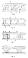
- Figures 3 to 5 illustrate different ridge profile geometries according to the above-mentioned embodiments of the invention.
- Fig. 3 shows the same geometry as Fig. 1 , i.e. both walls having the same profile of trapezoidal ridges 6, 8, each ridge 6 engaging the sides of two adjacent ridges 8 on the opposite wall.
- a connection between the contacting sides 6a and 8a may be achieved by pressing the walls 2 and 4 together to achieve either a frictional engagement between the opposing ridges, or even a friction welded connection.
- the pressure may be exerted by passing the folded tube between two suitably adjusted rolls.
- the connection may be achieved by brazing which will be described in more detail below.
- Fig. 4 and 5 display ridge geometries in which two ridges 16, 18 on the first and second walls only engage each other on one side, while a refrigerant passage 10 is formed on the other side.
- This design allows for a larger cross-section of the fluid passages 10.
- Each ridge 16, 18 engages a corresponding recess 19 in the opposing wall.
- This embodiment may be designed either with trapezoidal ridges as in Fig. 4 or with ridges having rounded edges as in Fig. 5 .
- FIG. 6 A variant not covered by the invention is shown in Fig. 6 using rectangular ridge profiles, but it may be embodied with trapezoidal profiles, too.
- the embodiment of Fig. 6 uses different profiles for upper and lower walls. Therefore, it might be preferable to construct a fluid tube with this design from two separate sheets rather than from one sheet folded at midpoint. The sheets could be rolled with the same roll but at different reductions.
- the upper wall has relatively high ridges 26, each engaging a shallow groove 30 formed between a couple of low ridges 28 on the lower wall.
- FIG. 7 A further variant is shown in Fig. 7 .
- a rectangular or otherwise shaped ridge 38 on the lower wall 4 engages a groove 37 formed between a couple of ridges 36a, 36b, formed in the upper wall 2.
- the ridges 36a, 36b reach as far as the lower wall and a refrigerant passage 10 is formed on the outer sides of ridges 36a, 36b. Since the contact surface 39 between ridges 36 and 38 is particularly large in this embodiment, the strength of the connection between upper and lower walls is excellent.
- Fig. 9a and 9b The variant shown in Fig. 9a and 9b is particularly suited for a frictional or friction welded connection between the upper and lower wall achieved by rolling.
- Fig. 9a shows the profile before rolling
- Fig. 9b shows the profile after rolling.
- the upper wall 2 is provided with main ridges 46 each having a flat top structured in small ridges 47 and engaging the flat inner surface of the lower wall 4.
- main ridges 46 each having a flat top structured in small ridges 47 and engaging the flat inner surface of the lower wall 4.
- the small ridges 47 are pressed into the inner surface of the lower wall and thus form corresponding small ridges 48 in the lower wall.
- This connection may either be the only connection of the tube, or may be combined with brazing.
- FIG. 8 A variant of the above variant is shown in Fig. 8 .
- trapezoidal ridges 46 on the upper wall engage the flat inner surface of the lower wall 4.
- All embodiments of the profiles may be produced by rolling a metal sheet or plate, preferably an aluminium alloy sheet.
- the sheet may either be blank, or may be clad on one or both sides with a brazing filler material.
- the clad layer will preferably have a thickness of 2 to 13% of the total thickness of the brazing sheet.
- the choice of brazing material will depend on the chosen method of "preliminary" connection of the tube walls, and on the selected brazing technique, as described below. To achieve a brazing connection between upper and lower walls, one may use a double clad sheet for one wall and a single clad sheet for the other.
- the length g was 2 mm.
- a photograph of the left profile is shown in Fig. 11 .
- This roll was used to roll an aluminium brazing sheet having a 5 % clad layer of brazing material.
- the aluminium core was made of an AA3003 aluminium alloy according to the classification of the Aluminium Association, and the clad layer was made of an AA4004 aluminium alloy.
- the result is shown in Fig. 12 .
- the roll produced an almost perfect trapezoidal profile of ridges.
- the clad layer accumulated mainly on the top of the ridges and the bottom of the grooves.
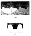
- FIG. 13 and 14 Another example of a brazing sheet rolled with the rough profile depicted on the left of Fig. 10 and the fine profile depicted on the right of Fig. 10 is shown in Fig. 13 and 14 , respectively.
- the "s" stands for side and "c” stands for centre.
- This brazing sheet had a core of AA3003-type alloy and a 10 % clad layer of an AA4045 aluminium alloy.
- the roll produced a very regular shape of trapezoidal ridges, with the best results achieved in the centre of the roll.
- the profile at the sides of the roll was also good.
- FIG. 15 A schematic cross-sectional of a tube made from a rolled brazing sheet product is shown in Fig. 15 before ( Fig. 15a ) and after brazing ( Fig. 15b ) .
- the clad layer 24 is pressed mainly to the top of the ridges and the bottom of the grooves during rolling.
- the molten filler metal flows into the gaps between the ridges 6 and 8 and thereby forms fillets 25 at the contact points of the opposing ridges.
- brazing technique may be used to braze the above-described tubes and the heat exchangers comprising such tubes.
- Nocolok ® registered trademark
- spraying the heat exchanger with flux before brazing is a laborious and therefore expensive process.
- the Nocolok ® process poses the problem of getting the flux inside the tubes. It is therefore more preferred to use one of the following fluxless brazing techniques.
- the parts to be brazed contain sufficient quantities of Mg as known in the art, such that, when heated in a brazing furnace under vacuum conditions, the Mg becomes sufficiently volatile to disrupt the oxide layer and permit the underlying aluminium filler metal to flow together.
- This brazing technique is especially suitable for the present invention, since Mg will accumulate inside the tube and will thus cause a better brazing result.
- the Mg content of the inner clad layer is preferably 0.2 to 1 %, for example 0.6 %.
- Nickel reacts exothermally with the underlying aluminium alloy, thereby disrupting the oxide layer and permitting the filler metal to flow together and join.
- Ni, Co or Fe or alloys thereof may be used, for example as known from US-6,379,818 and US-6,391,476 .
- polymer based brazing techniques uses an additional polymer layer on top of the clad layer containing particles of flux material.
- the polymer layer acts as an adhesive layer to the clad layer.
- the polymer will evaporate in the heat-up cycle during brazing, leaving only the flux material on the metal surface, for example as known from US-6,753,094 .
Landscapes
- Engineering & Computer Science (AREA)
- Mechanical Engineering (AREA)
- Physics & Mathematics (AREA)
- Thermal Sciences (AREA)
- General Engineering & Computer Science (AREA)
- Geometry (AREA)
- Heat-Exchange Devices With Radiators And Conduit Assemblies (AREA)
- Pressure Welding/Diffusion-Bonding (AREA)
- Rigid Pipes And Flexible Pipes (AREA)
- Metal Extraction Processes (AREA)
- Details Of Heat-Exchange And Heat-Transfer (AREA)
Claims (15)
- Tube (1) réalisé à partir d'un produit métallique galeté profilé, en particulier pour l'utilisation dans des échangeurs thermiques, le tube comprenant une première paroi (2) et une seconde paroi (4) formant deux parois opposées dudit tube, et une pluralité de structures de renforcement qui relient la première et la seconde paroi et qui forment des passages longitudinaux (10) pour transporter un fluide entre la première et la seconde paroi, et dans lequel chaque structure de renforcement comprend une nervure longitudinale (6, 16, 26, 36) sur la première paroi en projection vers la seconde paroi, et une nervure longitudinale (8, 18, 28) sur la seconde paroi en projection vers la première paroi, les nervures s'engageant mutuellement sur leurs côtés (8a, 8a), et les nervures sur la première et la seconde paroi possédant un profil choisi parmi le groupe comprenant un profil trapézoïdal et un profil en forme de cône, dans lequel les nervures sur la première et la seconde paroi sont plus larges à la base qu'à leur sommet, et dans lequel chaque paroi présente un profil avec des nervures (6, 8) espacées les unes des autres de telle façon qu'une gorge se forme entre deux nervures voisines,
caractérisé en ce que les deux côtés (6a) d'une nervure engagent les deux côtés (8a) d'une gorge dans la paroi opposée, en formant ainsi un passage longitudinal (10) dans la gorge. - Tube (1) réalisé à partir d'un produit métallique galeté profilé, en particulier pour l'utilisation dans des échangeurs thermiques, le tube comprenant une première paroi (2) et une seconde paroi (4) formant deux parois opposées dudit tube, et une pluralité de structures de renforcement qui relient la première et la seconde paroi et qui forment des passages longitudinaux (10) pour transporter un fluide entre la première et la seconde paroi, et dans lequel chaque structure de renforcement comprend une nervure longitudinale (16) sur la première paroi en projection vers la seconde paroi, et une nervure longitudinale (18) sur la seconde paroi en projection vers la première paroi, les nervures s'engageant mutuellement sur leurs côtés, et les nervures (16, 18) sur la première et la seconde paroi ayant un profil choisi parmi le groupe comprenant un profil trapézoïdal et un profil en forme de cône, dans lequel les nervures sur la première et la seconde paroi sont plus larges à leur base qu'à leur sommet, dans lequel chaque paroi présente un profil avec des nervures (16, 18) espacées les unes des autres de telle façon qu'une gorge se forme entre deux nervures voisines, dans lequel chaque nervure (16) engage une nervure (18) sur la paroi opposé sur un côté, en formant un passage à fluide sur son autre côté,
caractérisé en ce que le sommet de chaque nervure (16, 18) dans une paroi s'engage dans un évidement (19) formé dans l'autre paroi. - Tube selon la revendication 1 ou 2, dans lequel la première paroi (2) présente des nervures avec le même profil que la seconde paroi (4).
- Tube selon l'une quelconque des revendications 1 à 3, dans lequel chaque nervure sur la première et/ou sur la seconde paroi inclut une pluralité de découpes (20) formant des trous de communication pour amener des passages longitudinaux voisins (10) à communiquer les uns avec les autres.
- Tube selon l'une quelconque des revendications 1 à 4, dans lequel les nervures sur la première et la seconde paroi seront réunies les unes aux autres par une ou plusieurs techniques parmi le soudage par friction, le soudage résistif, ou le brasage.
- Tube selon l'une quelconque des revendications 1 à 5, dans lequel le produit métallique galeté profilé est réalisé à partir d'un produit en tôle à braser comprenant un alliage d'aluminium sur un côté ou sur les deux côtés, revêtu d'un matériau de brasage.
- Tube selon l'une quelconque des revendications 1 à 6, dans lequel la première paroi (2) et la seconde paroi (4) sont réunies l'une à l'autre au moyen d'un brasage.
- Produit métallique galeté pour produire la première et/ou la seconde paroi (2, 4) du tube selon l'une quelconque des revendications 1 à 7, ce produit présentant un profil tel que décrit dans la revendication 1 ou 2, et étant produit par galetage d'une tôle à braser revêtue sur au moins côté avec un matériau de brasage.
- Procédé pour produire un tube selon l'une quelconque des revendications 1 ou 3 à 7, comprenant les étapes consistant à :- produire la première et la seconde paroi par galetage d'une tôle métallique revêtue sur au moins un côté avec un matériau de brasage avec une paire de galets, l'un des galets ayant des gorges annulaires parallèles pour former des nervures sur un côté de la tôle, les nervures sur la première et sur la seconde paroi étant plus larges à la base qu'à leur sommet, et dans lequel chaque paroi présente un profil avec des nervures (6, 8) espacées les unes des autres de telle façon qu'une gorge se forme entre deux nervures voisines,- placer la première paroi (2) sur le sommet de la seconde paroi (4),- relier la première et la seconde paroi par serrage ou par galetage, de sorte que les deux côtés (6a) d'une nervure engagent les deux côtés (8a) d'une gorge dans la paroi opposée, en formant ainsi un passage longitudinal (10) dans la gorge.
- Procédé pour produire un tube selon l'une quelconque des revendications 2 à 7, comprenant les étapes consistant à :- produire la première et la seconde paroi par galetage d'une tôle métallique revêtue sur au moins un côté avec un matériau de brasage avec une paire de galets, l'un des galets ayant des gorges annulaires parallèles pour former des nervures sur un côté de la tôle, les nervures sur la première et sur la seconde paroi étant plus larges à la base qu'à leur sommet, et dans lequel chaque paroi présente un profil avec des nervures (16, 18) espacées les unes des autres de telle façon qu'une gorge se forme entre deux nervures voisines,- placer la première paroi (2) sur le sommet de la seconde paroi (4),- relier la première et la seconde paroi par serrage ou par galetage, de sorte que chaque nervure (16) engage une nervure (18) sur la paroi opposée sur un côté, en formant un passage à fluide sur son autre côté, et dans lequel le sommet de chaque nervure (16, 18) dans une paroi s'engage dans un évidement (19) formé dans l'autre paroi.
- Procédé selon la revendication 9 ou 10, dans lequel la première et la seconde paroi sont serrées ensemble en formant une bride (14) sur l'une des parois, qui tient l'autre paroi.
- Procédé selon la revendication 9, 10 ou 11, dans lequel la première et la seconde paroi sont réunies ensemble par galetage, en provoquant ainsi une liaison par friction et/ou une liaison soudée par friction entre les côtés (6a, 8a) des nervures qui s'engagent mutuellement.
- Procédé pour produire un échangeur de chaleur comprenant une paire de collecteurs, une pluralité de tubes à réfrigérant réunis à chaque extrémité à l'un des collecteurs, et des ailettes ondulées disposées entre des tubes à réfrigérants adjacents, comprenant les étapes consistant à :- produire les tubes à réfrigérant selon le procédé de l'une quelconque des revendications 9 à 12,- assembler les collecteurs, les tubes à réfrigérants, et les ailettes ondulées, et- braser l'ensemble de l'échangeur à chaleur.
- Procédé selon la revendication 13, dans lequel les tubes sont réalisés à partir d'une tôle d'aluminium revêtue au moins sur le côté profilé avec un matériau de brasage, et la première et la seconde paroi sont brasées ensemble pendant le brasage de l'ensemble de l'échangeur à chaleur.
- Procédé selon la revendication 14, dans lequel le brasage de l'ensemble de l'échangeur à chaleur a lieu au moyen d'un brasage sous vide ou d'un brasage sans flux.
Priority Applications (1)
| Application Number | Priority Date | Filing Date | Title |
|---|---|---|---|
| EP05794807A EP1802932B1 (fr) | 2004-10-22 | 2005-10-04 | Tube en produit metallique profile et procede de production |
Applications Claiming Priority (3)
| Application Number | Priority Date | Filing Date | Title |
|---|---|---|---|
| EP04077907 | 2004-10-22 | ||
| EP05794807A EP1802932B1 (fr) | 2004-10-22 | 2005-10-04 | Tube en produit metallique profile et procede de production |
| PCT/EP2005/010807 WO2006045415A1 (fr) | 2004-10-22 | 2005-10-04 | Tube en produit metallique profile et procede de production |
Publications (2)
| Publication Number | Publication Date |
|---|---|
| EP1802932A1 EP1802932A1 (fr) | 2007-07-04 |
| EP1802932B1 true EP1802932B1 (fr) | 2009-06-03 |
Family
ID=34928589
Family Applications (1)
| Application Number | Title | Priority Date | Filing Date |
|---|---|---|---|
| EP05794807A Expired - Lifetime EP1802932B1 (fr) | 2004-10-22 | 2005-10-04 | Tube en produit metallique profile et procede de production |
Country Status (10)
| Country | Link |
|---|---|
| US (1) | US7690114B2 (fr) |
| EP (1) | EP1802932B1 (fr) |
| JP (1) | JP4926972B2 (fr) |
| KR (1) | KR101181615B1 (fr) |
| CN (1) | CN101065633B (fr) |
| AT (1) | ATE433087T1 (fr) |
| CA (1) | CA2591683C (fr) |
| DE (2) | DE602005014796D1 (fr) |
| FR (1) | FR2878946B1 (fr) |
| WO (1) | WO2006045415A1 (fr) |
Families Citing this family (8)
| Publication number | Priority date | Publication date | Assignee | Title |
|---|---|---|---|---|
| DE102008051894A1 (de) | 2008-10-16 | 2010-05-06 | Behr Gmbh & Co. Kg | Belastungsangepasstes Strukturteil aus Metall für einen Wärmetauscher, Verfahren zur Herstellung eines belastungsangepassten Strukturteils, Wärmetauscher |
| CN101832726B (zh) * | 2009-03-11 | 2012-01-25 | 三花丹佛斯(杭州)微通道换热器有限公司 | 一种用于热交换器的散热管及其制造方法 |
| US8174288B2 (en) * | 2009-04-13 | 2012-05-08 | International Business Machines Corporation | Voltage conversion and integrated circuits with stacked voltage domains |
| US20150026981A1 (en) * | 2013-07-24 | 2015-01-29 | Asia Vital Components Co., Ltd. | Manufacturing mehtod of vapor chamber structure |
| DE102014002829A1 (de) * | 2014-02-27 | 2015-08-27 | Wieland-Werke Ag | Metallisches Wärmeaustauscherrohr |
| CN113020264A (zh) * | 2021-03-25 | 2021-06-25 | 太原理工大学 | 一种形成交织结合界面的金属复合板轧制方法 |
| CN113231469B (zh) * | 2021-05-10 | 2023-04-18 | 贵州大学 | 一种锌基复合材料用铝合金材料包套热轧的方法 |
| CN116871837A (zh) * | 2023-09-04 | 2023-10-13 | 中山莱通金属科技有限公司 | 一种低成本平行流散热器用微通道多孔扁管工艺 |
Family Cites Families (17)
| Publication number | Priority date | Publication date | Assignee | Title |
|---|---|---|---|---|
| JPS5671520A (en) * | 1979-11-13 | 1981-06-15 | Nissan Motor Co Ltd | Production of tube structural body |
| US5186250A (en) | 1990-05-11 | 1993-02-16 | Showa Aluminum Kabushiki Kaisha | Tube for heat exchangers and a method for manufacturing the tube |
| US5931226A (en) | 1993-03-26 | 1999-08-03 | Showa Aluminum Corporation | Refrigerant tubes for heat exchangers |
| DE19518657A1 (de) * | 1995-04-26 | 1996-10-31 | Lingemann Helmut Gmbh & Co | Mehrkammerflachrohr für Wärmetauscher sowie Verfahren zu seiner Herstellung |
| WO1996034245A1 (fr) | 1995-04-26 | 1996-10-31 | Helmut Lingemann Gmbh & Co. | Tube plat a cavites multiples pour echangeurs de chaleur et son procede de fabrication |
| JP3947830B2 (ja) * | 1996-06-26 | 2007-07-25 | 昭和電工株式会社 | 偏平状熱交換管の製造方法 |
| EP1180403B1 (fr) * | 1996-06-26 | 2004-09-22 | Showa Denko K.K. | Procédé pour la fabrication de tubes plats pour échangeurs de chaleur |
| US5937517A (en) * | 1997-11-12 | 1999-08-17 | Eastman Kodak Company | Method of manufacturing bonded dual extruded, high fin density heat sinks |
| JP2000074586A (ja) | 1998-08-31 | 2000-03-14 | Toyo Radiator Co Ltd | 熱交換器用偏平チューブ |
| BR0009945B1 (pt) | 1999-04-22 | 2012-02-22 | material laminado compósito bobinado para brasagem e método de fabricação de material laminado. | |
| MXPA01011258A (es) | 1999-05-21 | 2002-08-12 | Corus Aluminium Walzprod Gmbh | Producto de hoja latonada y metodo para su fabricacion. |
| JP2000346576A (ja) | 1999-05-31 | 2000-12-15 | Mitsubishi Heavy Ind Ltd | 熱交換器およびその製造方法 |
| US6209202B1 (en) | 1999-08-02 | 2001-04-03 | Visteon Global Technologies, Inc. | Folded tube for a heat exchanger and method of making same |
| EP1265725B1 (fr) | 2000-03-10 | 2007-07-18 | Aleris Aluminum Koblenz GmbH | Tole brasee et procede de fabrication d'un ensemble au moyen de cette tole brasee |
| JP4536273B2 (ja) | 2001-01-31 | 2010-09-01 | 株式会社ティラド | 熱交換器用偏平チューブおよび熱交換器の製造方法 |
| WO2002100567A1 (fr) * | 2001-06-08 | 2002-12-19 | Showa Denko K.K. | Plaque metallique pour la production d'un tube plat, tube plat obtenu et son procede de production |
| JP3951812B2 (ja) * | 2001-06-08 | 2007-08-01 | 昭和電工株式会社 | 偏平管製造用金属板、偏平管および偏平管の製造方法 |
-
2005
- 2005-10-04 EP EP05794807A patent/EP1802932B1/fr not_active Expired - Lifetime
- 2005-10-04 KR KR1020077011331A patent/KR101181615B1/ko not_active Expired - Fee Related
- 2005-10-04 JP JP2007537150A patent/JP4926972B2/ja not_active Expired - Fee Related
- 2005-10-04 WO PCT/EP2005/010807 patent/WO2006045415A1/fr not_active Ceased
- 2005-10-04 CN CN2005800354626A patent/CN101065633B/zh not_active Expired - Fee Related
- 2005-10-04 US US11/242,124 patent/US7690114B2/en not_active Expired - Fee Related
- 2005-10-04 DE DE602005014796T patent/DE602005014796D1/de not_active Expired - Lifetime
- 2005-10-04 CA CA2591683A patent/CA2591683C/fr not_active Expired - Fee Related
- 2005-10-04 AT AT05794807T patent/ATE433087T1/de not_active IP Right Cessation
- 2005-10-10 DE DE102005048407A patent/DE102005048407A1/de not_active Ceased
- 2005-10-17 FR FR0510544A patent/FR2878946B1/fr not_active Expired - Fee Related
Also Published As
| Publication number | Publication date |
|---|---|
| DE602005014796D1 (de) | 2009-07-16 |
| CN101065633A (zh) | 2007-10-31 |
| WO2006045415A1 (fr) | 2006-05-04 |
| JP4926972B2 (ja) | 2012-05-09 |
| JP2008516778A (ja) | 2008-05-22 |
| CA2591683A1 (fr) | 2006-05-04 |
| CA2591683C (fr) | 2013-12-10 |
| FR2878946A1 (fr) | 2006-06-09 |
| EP1802932A1 (fr) | 2007-07-04 |
| DE102005048407A1 (de) | 2006-07-27 |
| ATE433087T1 (de) | 2009-06-15 |
| KR101181615B1 (ko) | 2012-09-10 |
| FR2878946B1 (fr) | 2010-08-20 |
| KR20070074627A (ko) | 2007-07-12 |
| CN101065633B (zh) | 2011-05-25 |
| US20060112557A1 (en) | 2006-06-01 |
| US7690114B2 (en) | 2010-04-06 |
Similar Documents
| Publication | Publication Date | Title |
|---|---|---|
| US5185925A (en) | Method of manufacturing a tube for a heat exchanger | |
| US6899168B2 (en) | Heat exchanger and a method for producing a heat exchanger | |
| US7749609B2 (en) | Metal plate for producing flat tube, flat tube and process for producing the flat tube | |
| AU722225B2 (en) | Process for producing flat heat exchange tubes | |
| EP0881449A2 (fr) | Tubes de refroidissement pour échangeurs de chaleur | |
| US9593889B2 (en) | Heat exchanger construction | |
| JP2007139417A (ja) | 偏平管製造用金属板、偏平管および偏平管の製造方法 | |
| EP1802932B1 (fr) | Tube en produit metallique profile et procede de production | |
| JPH09273883A (ja) | 熱交換器用扁平チューブおよび同チューブを備えた熱交換器 | |
| US20020057941A1 (en) | Connection structure between a pipe and a tube for use in a heat exchanger | |
| CN100520267C (zh) | 用于换热器的管型面 | |
| JP2004167601A (ja) | 偏平管半製品およびその製造方法、偏平管、偏平管を用いた熱交換器およびその製造方法 | |
| JP2000193387A (ja) | 偏平状熱交換管およびその製造方法 | |
| EP1027942A1 (fr) | Tube pour echangeur de chaleur et procede de fabrication dudit tube | |
| EP4065914B1 (fr) | Tube d'échangeur de chaleur plat | |
| US5881457A (en) | Method of making refrigerant tubes for heat exchangers | |
| JP3095878B2 (ja) | 熱交換器 | |
| US20020007940A1 (en) | Brazed tube for a heat exchanger, method of manufacture and exchanger | |
| US20050045315A1 (en) | Concentric tube heat exchanger and end seal therefor | |
| JP2006153354A (ja) | 熱交換器 | |
| JPH0723101Y2 (ja) | アルミニウム製積層型熱交換器製造用ろう付治具 | |
| JP3209856B2 (ja) | アルミニウム材製熱交換器の製造方法 | |
| JPH05228620A (ja) | アルミニウム製熱交換器の製造方法 | |
| JP2006112651A (ja) | 熱交換器 |
Legal Events
| Date | Code | Title | Description |
|---|---|---|---|
| PUAI | Public reference made under article 153(3) epc to a published international application that has entered the european phase |
Free format text: ORIGINAL CODE: 0009012 |
|
| 17P | Request for examination filed |
Effective date: 20070306 |
|
| AK | Designated contracting states |
Kind code of ref document: A1 Designated state(s): AT BE BG CH CY CZ DE DK EE ES FI FR GB GR HU IE IS IT LI LT LU LV MC NL PL PT RO SE SI SK TR |
|
| 17Q | First examination report despatched |
Effective date: 20070731 |
|
| DAX | Request for extension of the european patent (deleted) | ||
| GRAP | Despatch of communication of intention to grant a patent |
Free format text: ORIGINAL CODE: EPIDOSNIGR1 |
|
| GRAS | Grant fee paid |
Free format text: ORIGINAL CODE: EPIDOSNIGR3 |
|
| GRAA | (expected) grant |
Free format text: ORIGINAL CODE: 0009210 |
|
| AK | Designated contracting states |
Kind code of ref document: B1 Designated state(s): AT BE BG CH CY CZ DE DK EE ES FI FR GB GR HU IE IS IT LI LT LU LV MC NL PL PT RO SE SI SK TR |
|
| REG | Reference to a national code |
Ref country code: GB Ref legal event code: FG4D |
|
| REG | Reference to a national code |
Ref country code: CH Ref legal event code: EP |
|
| REG | Reference to a national code |
Ref country code: IE Ref legal event code: FG4D |
|
| REF | Corresponds to: |
Ref document number: 602005014796 Country of ref document: DE Date of ref document: 20090716 Kind code of ref document: P |
|
| REG | Reference to a national code |
Ref country code: DE Ref legal event code: R096 Ref document number: 602005014796 Country of ref document: DE Effective date: 20090716 |
|
| PG25 | Lapsed in a contracting state [announced via postgrant information from national office to epo] |
Ref country code: LT Free format text: LAPSE BECAUSE OF FAILURE TO SUBMIT A TRANSLATION OF THE DESCRIPTION OR TO PAY THE FEE WITHIN THE PRESCRIBED TIME-LIMIT Effective date: 20090603 Ref country code: FI Free format text: LAPSE BECAUSE OF FAILURE TO SUBMIT A TRANSLATION OF THE DESCRIPTION OR TO PAY THE FEE WITHIN THE PRESCRIBED TIME-LIMIT Effective date: 20090603 Ref country code: AT Free format text: LAPSE BECAUSE OF FAILURE TO SUBMIT A TRANSLATION OF THE DESCRIPTION OR TO PAY THE FEE WITHIN THE PRESCRIBED TIME-LIMIT Effective date: 20090603 |
|
| NLV1 | Nl: lapsed or annulled due to failure to fulfill the requirements of art. 29p and 29m of the patents act | ||
| PG25 | Lapsed in a contracting state [announced via postgrant information from national office to epo] |
Ref country code: PL Free format text: LAPSE BECAUSE OF FAILURE TO SUBMIT A TRANSLATION OF THE DESCRIPTION OR TO PAY THE FEE WITHIN THE PRESCRIBED TIME-LIMIT Effective date: 20090603 Ref country code: LV Free format text: LAPSE BECAUSE OF FAILURE TO SUBMIT A TRANSLATION OF THE DESCRIPTION OR TO PAY THE FEE WITHIN THE PRESCRIBED TIME-LIMIT Effective date: 20090603 Ref country code: SE Free format text: LAPSE BECAUSE OF FAILURE TO SUBMIT A TRANSLATION OF THE DESCRIPTION OR TO PAY THE FEE WITHIN THE PRESCRIBED TIME-LIMIT Effective date: 20090903 Ref country code: SI Free format text: LAPSE BECAUSE OF FAILURE TO SUBMIT A TRANSLATION OF THE DESCRIPTION OR TO PAY THE FEE WITHIN THE PRESCRIBED TIME-LIMIT Effective date: 20090603 Ref country code: NL Free format text: LAPSE BECAUSE OF FAILURE TO SUBMIT A TRANSLATION OF THE DESCRIPTION OR TO PAY THE FEE WITHIN THE PRESCRIBED TIME-LIMIT Effective date: 20090603 |
|
| PG25 | Lapsed in a contracting state [announced via postgrant information from national office to epo] |
Ref country code: ES Free format text: LAPSE BECAUSE OF FAILURE TO SUBMIT A TRANSLATION OF THE DESCRIPTION OR TO PAY THE FEE WITHIN THE PRESCRIBED TIME-LIMIT Effective date: 20090914 Ref country code: EE Free format text: LAPSE BECAUSE OF FAILURE TO SUBMIT A TRANSLATION OF THE DESCRIPTION OR TO PAY THE FEE WITHIN THE PRESCRIBED TIME-LIMIT Effective date: 20090603 Ref country code: RO Free format text: LAPSE BECAUSE OF FAILURE TO SUBMIT A TRANSLATION OF THE DESCRIPTION OR TO PAY THE FEE WITHIN THE PRESCRIBED TIME-LIMIT Effective date: 20090603 Ref country code: IS Free format text: LAPSE BECAUSE OF FAILURE TO SUBMIT A TRANSLATION OF THE DESCRIPTION OR TO PAY THE FEE WITHIN THE PRESCRIBED TIME-LIMIT Effective date: 20091003 Ref country code: CZ Free format text: LAPSE BECAUSE OF FAILURE TO SUBMIT A TRANSLATION OF THE DESCRIPTION OR TO PAY THE FEE WITHIN THE PRESCRIBED TIME-LIMIT Effective date: 20090603 |
|
| PG25 | Lapsed in a contracting state [announced via postgrant information from national office to epo] |
Ref country code: SK Free format text: LAPSE BECAUSE OF FAILURE TO SUBMIT A TRANSLATION OF THE DESCRIPTION OR TO PAY THE FEE WITHIN THE PRESCRIBED TIME-LIMIT Effective date: 20090603 Ref country code: BE Free format text: LAPSE BECAUSE OF FAILURE TO SUBMIT A TRANSLATION OF THE DESCRIPTION OR TO PAY THE FEE WITHIN THE PRESCRIBED TIME-LIMIT Effective date: 20090603 |
|
| PG25 | Lapsed in a contracting state [announced via postgrant information from national office to epo] |
Ref country code: BG Free format text: LAPSE BECAUSE OF FAILURE TO SUBMIT A TRANSLATION OF THE DESCRIPTION OR TO PAY THE FEE WITHIN THE PRESCRIBED TIME-LIMIT Effective date: 20090903 Ref country code: PT Free format text: LAPSE BECAUSE OF FAILURE TO SUBMIT A TRANSLATION OF THE DESCRIPTION OR TO PAY THE FEE WITHIN THE PRESCRIBED TIME-LIMIT Effective date: 20091003 |
|
| PLBE | No opposition filed within time limit |
Free format text: ORIGINAL CODE: 0009261 |
|
| STAA | Information on the status of an ep patent application or granted ep patent |
Free format text: STATUS: NO OPPOSITION FILED WITHIN TIME LIMIT |
|
| PG25 | Lapsed in a contracting state [announced via postgrant information from national office to epo] |
Ref country code: DK Free format text: LAPSE BECAUSE OF FAILURE TO SUBMIT A TRANSLATION OF THE DESCRIPTION OR TO PAY THE FEE WITHIN THE PRESCRIBED TIME-LIMIT Effective date: 20090603 |
|
| 26N | No opposition filed |
Effective date: 20100304 |
|
| PG25 | Lapsed in a contracting state [announced via postgrant information from national office to epo] |
Ref country code: MC Free format text: LAPSE BECAUSE OF NON-PAYMENT OF DUE FEES Effective date: 20091031 |
|
| REG | Reference to a national code |
Ref country code: CH Ref legal event code: PL |
|
| REG | Reference to a national code |
Ref country code: DE Ref legal event code: R097 Ref document number: 602005014796 Country of ref document: DE Effective date: 20100304 |
|
| REG | Reference to a national code |
Ref country code: IE Ref legal event code: MM4A |
|
| REG | Reference to a national code |
Ref country code: FR Ref legal event code: ST Effective date: 20100630 |
|
| PG25 | Lapsed in a contracting state [announced via postgrant information from national office to epo] |
Ref country code: FR Free format text: LAPSE BECAUSE OF NON-PAYMENT OF DUE FEES Effective date: 20091102 |
|
| PG25 | Lapsed in a contracting state [announced via postgrant information from national office to epo] |
Ref country code: CH Free format text: LAPSE BECAUSE OF NON-PAYMENT OF DUE FEES Effective date: 20091031 Ref country code: LI Free format text: LAPSE BECAUSE OF NON-PAYMENT OF DUE FEES Effective date: 20091031 Ref country code: IE Free format text: LAPSE BECAUSE OF NON-PAYMENT OF DUE FEES Effective date: 20091004 Ref country code: GR Free format text: LAPSE BECAUSE OF FAILURE TO SUBMIT A TRANSLATION OF THE DESCRIPTION OR TO PAY THE FEE WITHIN THE PRESCRIBED TIME-LIMIT Effective date: 20090904 |
|
| PG25 | Lapsed in a contracting state [announced via postgrant information from national office to epo] |
Ref country code: GB Free format text: LAPSE BECAUSE OF NON-PAYMENT OF DUE FEES Effective date: 20091004 |
|
| PG25 | Lapsed in a contracting state [announced via postgrant information from national office to epo] |
Ref country code: IT Free format text: LAPSE BECAUSE OF FAILURE TO SUBMIT A TRANSLATION OF THE DESCRIPTION OR TO PAY THE FEE WITHIN THE PRESCRIBED TIME-LIMIT Effective date: 20090603 |
|
| PG25 | Lapsed in a contracting state [announced via postgrant information from national office to epo] |
Ref country code: LU Free format text: LAPSE BECAUSE OF NON-PAYMENT OF DUE FEES Effective date: 20091004 |
|
| PG25 | Lapsed in a contracting state [announced via postgrant information from national office to epo] |
Ref country code: HU Free format text: LAPSE BECAUSE OF FAILURE TO SUBMIT A TRANSLATION OF THE DESCRIPTION OR TO PAY THE FEE WITHIN THE PRESCRIBED TIME-LIMIT Effective date: 20091204 |
|
| PG25 | Lapsed in a contracting state [announced via postgrant information from national office to epo] |
Ref country code: TR Free format text: LAPSE BECAUSE OF FAILURE TO SUBMIT A TRANSLATION OF THE DESCRIPTION OR TO PAY THE FEE WITHIN THE PRESCRIBED TIME-LIMIT Effective date: 20090603 |
|
| PG25 | Lapsed in a contracting state [announced via postgrant information from national office to epo] |
Ref country code: CY Free format text: LAPSE BECAUSE OF FAILURE TO SUBMIT A TRANSLATION OF THE DESCRIPTION OR TO PAY THE FEE WITHIN THE PRESCRIBED TIME-LIMIT Effective date: 20090603 |
|
| PGFP | Annual fee paid to national office [announced via postgrant information from national office to epo] |
Ref country code: DE Payment date: 20190918 Year of fee payment: 15 |
|
| REG | Reference to a national code |
Ref country code: DE Ref legal event code: R082 Ref document number: 602005014796 Country of ref document: DE Representative=s name: WEICKMANN & WEICKMANN PATENT- UND RECHTSANWAEL, DE |
|
| REG | Reference to a national code |
Ref country code: DE Ref legal event code: R119 Ref document number: 602005014796 Country of ref document: DE |
|
| PG25 | Lapsed in a contracting state [announced via postgrant information from national office to epo] |
Ref country code: DE Free format text: LAPSE BECAUSE OF NON-PAYMENT OF DUE FEES Effective date: 20210501 |
|
| P01 | Opt-out of the competence of the unified patent court (upc) registered |
Effective date: 20230517 |