EP1802995B1 - Radar large bande ameliore - Google Patents
Radar large bande ameliore Download PDFInfo
- Publication number
- EP1802995B1 EP1802995B1 EP04793790A EP04793790A EP1802995B1 EP 1802995 B1 EP1802995 B1 EP 1802995B1 EP 04793790 A EP04793790 A EP 04793790A EP 04793790 A EP04793790 A EP 04793790A EP 1802995 B1 EP1802995 B1 EP 1802995B1
- Authority
- EP
- European Patent Office
- Prior art keywords
- signal
- measurements
- velocity
- target
- range
- Prior art date
- Legal status (The legal status is an assumption and is not a legal conclusion. Google has not performed a legal analysis and makes no representation as to the accuracy of the status listed.)
- Expired - Lifetime
Links
- 238000000034 method Methods 0.000 claims abstract description 35
- 230000003466 anti-cipated effect Effects 0.000 claims abstract description 29
- 230000002596 correlated effect Effects 0.000 claims abstract description 21
- 230000001934 delay Effects 0.000 claims abstract description 9
- 230000000875 corresponding effect Effects 0.000 claims abstract description 7
- 238000005259 measurement Methods 0.000 claims description 22
- 238000012545 processing Methods 0.000 claims description 3
- 238000012935 Averaging Methods 0.000 claims description 2
- 238000010586 diagram Methods 0.000 description 5
- 230000008901 benefit Effects 0.000 description 4
- 238000004364 calculation method Methods 0.000 description 4
- 230000001427 coherent effect Effects 0.000 description 4
- 230000006870 function Effects 0.000 description 4
- 230000000694 effects Effects 0.000 description 3
- 230000003111 delayed effect Effects 0.000 description 2
- 230000001419 dependent effect Effects 0.000 description 2
- 238000001514 detection method Methods 0.000 description 2
- 230000035945 sensitivity Effects 0.000 description 2
- 238000004088 simulation Methods 0.000 description 2
- 230000015556 catabolic process Effects 0.000 description 1
- 238000006731 degradation reaction Methods 0.000 description 1
- 238000013461 design Methods 0.000 description 1
- 230000005611 electricity Effects 0.000 description 1
- 230000014509 gene expression Effects 0.000 description 1
- 230000036039 immunity Effects 0.000 description 1
- 230000010354 integration Effects 0.000 description 1
- 238000002955 isolation Methods 0.000 description 1
- 230000003287 optical effect Effects 0.000 description 1
- 230000001902 propagating effect Effects 0.000 description 1
- 230000002441 reversible effect Effects 0.000 description 1
- 238000005070 sampling Methods 0.000 description 1
- 238000001228 spectrum Methods 0.000 description 1
Images

Classifications
-
- G—PHYSICS
- G01—MEASURING; TESTING
- G01S—RADIO DIRECTION-FINDING; RADIO NAVIGATION; DETERMINING DISTANCE OR VELOCITY BY USE OF RADIO WAVES; LOCATING OR PRESENCE-DETECTING BY USE OF THE REFLECTION OR RERADIATION OF RADIO WAVES; ANALOGOUS ARRANGEMENTS USING OTHER WAVES
- G01S13/00—Systems using the reflection or reradiation of radio waves, e.g. radar systems; Analogous systems using reflection or reradiation of waves whose nature or wavelength is irrelevant or unspecified
- G01S13/02—Systems using reflection of radio waves, e.g. primary radar systems; Analogous systems
- G01S13/0209—Systems with very large relative bandwidth, i.e. larger than 10 %, e.g. baseband, pulse, carrier-free, ultrawideband
-
- G—PHYSICS
- G01—MEASURING; TESTING
- G01S—RADIO DIRECTION-FINDING; RADIO NAVIGATION; DETERMINING DISTANCE OR VELOCITY BY USE OF RADIO WAVES; LOCATING OR PRESENCE-DETECTING BY USE OF THE REFLECTION OR RERADIATION OF RADIO WAVES; ANALOGOUS ARRANGEMENTS USING OTHER WAVES
- G01S13/00—Systems using the reflection or reradiation of radio waves, e.g. radar systems; Analogous systems using reflection or reradiation of waves whose nature or wavelength is irrelevant or unspecified
- G01S13/02—Systems using reflection of radio waves, e.g. primary radar systems; Analogous systems
- G01S13/50—Systems of measurement based on relative movement of target
- G01S13/52—Discriminating between fixed and moving objects or between objects moving at different speeds
- G01S13/522—Discriminating between fixed and moving objects or between objects moving at different speeds using transmissions of interrupted pulse modulated waves
- G01S13/524—Discriminating between fixed and moving objects or between objects moving at different speeds using transmissions of interrupted pulse modulated waves based upon the phase or frequency shift resulting from movement of objects, with reference to the transmitted signals, e.g. coherent MTi
- G01S13/53—Discriminating between fixed and moving objects or between objects moving at different speeds using transmissions of interrupted pulse modulated waves based upon the phase or frequency shift resulting from movement of objects, with reference to the transmitted signals, e.g. coherent MTi performing filtering on a single spectral line and associated with one or more range gates with a phase detector or a frequency mixer to extract the Doppler information, e.g. pulse Doppler radar
- G01S13/532—Discriminating between fixed and moving objects or between objects moving at different speeds using transmissions of interrupted pulse modulated waves based upon the phase or frequency shift resulting from movement of objects, with reference to the transmitted signals, e.g. coherent MTi performing filtering on a single spectral line and associated with one or more range gates with a phase detector or a frequency mixer to extract the Doppler information, e.g. pulse Doppler radar using a bank of range gates or a memory matrix
Definitions
- the invention refers to a method and device for wideband radar.
- the method comprises:
- the invention also refers to a control device in a wideband radar system, arranged to carry out the above steps.
- range resolution is inversely proportional to the bandwidth used for the radar.
- velocity resolution depends inversely on integration of time.
- a challenge in the design of broadband radar systems is to achieve velocity resolution as good as the range resolution.
- the range resolution is normally better than required.
- GB 2259820 relates to a noise radar where a random code is generated and used to phase-modulate the transmitted signal, which is transmitted in a pulsed manner. In this way, an opportunity is given to receive each transmitter signal during periods between pulses.
- US 4443799 relates to a radar system utilizing a spread spectrum and a combination of coherent and non-coherent signal processing techniques.
- the invention aims to remedy the above stated problem by a method and a device as stated below.
- the method is intended to be implemented in a radar system using a wideband signal, with bandwidth B.
- Examples of radar using a wideband signal are Noise Radar and chirp pulse radar.
- the invention uses a signal generator for generating the wideband signal.
- the signal is copied and advantageously stored in a memory.
- the wideband signal is also transmitted by a sending antenna.
- the returned echo signal is received and amplified.
- Both the transmitted and received signal is divided into N f subsequent frequency bands b.
- the frequency bands b may have equal bandwidth B/N f , but may also have different bandwidth.
- Suitable means for dividing the stored and received signal into frequency bands is a filter bank for analog signals or digital filters in case the stored and received signals have been converted into digital signals.
- the return echo signal is delayed because of the transmitted signal making a round-trip propagating to a target and back to a receiving antenna.
- the transmitted signal also undergoes a Doppler Stretching when reflected by the target, due to the motion of the target, and becomes part of the return signal.
- the Doppler Stretching becomes a Doppler frequency shift.
- the stored and divided signal is being manipulated such that anticipated delays and Doppler stretches are added to the stored signal for each N f frequency band b.
- This manipulated signal is hereinafter called the anticipated signal and refers to one signal and thus one filter for each delay (i.e. a number of N d filters), and one signal and thus one filter for each Doppler stretch (i.e. a number of N D filters).
- the method comprises the step of correlating corresponding frequency bands b in the divided received signal and the anticipated signals, i.e. the N d delayed and the N D Doppler stretched copies of the transmitted signal are correlated with the received signal.
- This procedure takes place in a correlator means comprising a correlation cluster giving the N d N D correlated signals.
- the output from the correlator cluster yields a high value if an anticipated signal is matched with a similar return signal and a low value if there is a mismatch.
- match refers to two signals being identical or similar.
- the term "match” or "correlated” refers to a probability or probability function describing the probability of a target hit, i.e. the probability of finding a target at a range R with velocity v at a certain moment in time.
- the output from the correlator means is a number of correlated signals describing a range R and velocity v plane, and amplitudes in a direction orthogonal to the R and v plane. The amplitudes describe the high and low values in the correlated signal, i.e. if there is a match or nor. If there is a match the anticipated scenario for a target hit is identical or at least similar to the return signal from a target hit.
- the correlated signals thus give an output revealing the range R and velocity v of a target.
- the N d N D correlated signals are then averaged into a number of N f averaged signals in order to give a good estimate of the echo return for each range/delay and velocity/Doppler stretch combination.
- the range resolution ⁇ R will thus increase with a factor N b . Since it is possible to create a mean value over a number of N b measurements, i.e. one measurement for each part with a bandwidth b, the range resolution is improved with a factor equal to the square root of N b .
- Equation 3 now gives that the velocity resolution ⁇ v is improved with a factor equal to the square root of N b .
- the averaged signals are put through a detector means.
- the simplest form of a detector means may be described as a threshold circuit that gives logical "LOW” output below the threshold level and a logical “HIGH” output above the threshold level.
- a "LOW” output indicates large probability for "no target present” and a "HIGH” output indicates large probability for "target present”.
- a detector may also give target size information by using different threshold levels for different target sizes.
- the detected signals are processed in a logic means where the range (R) to a target and velocity (v) of the target is determined.
- the logic circuit reports for which range/velocity combinations there is high probability for a target.
- the divided received signal is transmitted through a switch cluster comprising a number of N f switches for clearing a signal that is evidently wrong in order to reduce interference from both intentional and unintentional jamming. For example, all jammed frequency sub bands will be excluded in the calculation of the average value by opening the correct switches in the switch cluster.
- One advantage of this procedure is that all jammed frequency sub bands will be excluded in the calculation of the average value. For example, a 1 bit A/D converter may be used and the procedure excluding jammed parts of the frequency band gives graceful degradation.
- the present invention has the advantage of gaining velocity resolution at the price of reduced range resolution, but where the range resolution still is good enough for detecting moving targets such as air planes etc.
- the invention also gives a system with high immunity against interference and reduced dynamic range requirements in the A/D-converters.
- a suitable bandwidth of the wideband signal is 10 GHz in the range 8-18 GHz, but other frequency ranges are also possible.
- the wideband signal is preferably continuous but may be in the form of pulses.
- Coherent noise radar is a method for radar where both phase and amplitude is correlated. In the non-coherent case only the amplitude of the signals is correlated.
- the present invention may use both types of wideband signals.
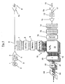
- Fig. 1 schematically shows a block diagram over the method and the radar and control device according to one embodiment of the invention.
- a wideband signal 1, with bandwidth B, is generated in a Wideband signal generator 2.
- the signal 1 is then processed in a band pass filter 3 (BP-filter) in order to remove frequency contents outside a filter bank.
- the filtered signal 4 is then enhanced in a power amplifier 5 and the enhanced signal 6 is then transmitted 6' via a transmitting antenna Tx.
- BP-filter band pass filter
- the enhanced signal 6 is copied after the power amplifier 5 and is then frequency divided by a BP-filter bank 7 into a number of N f frequency bands.
- the divided signals are then converted from analog signals into corresponding digital signals in an A/D-converter cluster 8.
- the A/D converted signals are stored in a Memory 9.
- the stored signals are then manipulated such that N d anticipated delays and N D Doppler stretches are added to the stored signal for each number N f of frequency bands.
- This manipulated signal is hereinafter called the anticipated signals 10 and refers to a number of N d N D (N d times N D ) filters comprising one filter for each delay, i.e. a number of N d filters for each delay and one filter for each Doppler stretch, i.e. a number of N D filters for each Doppler stretch.
- the number of filters depends on the instrumented range, the range resolution, the velocity limits, the velocity resolution and the number of frequency sub-bands.
- Each filter is optimized for one range and one velocity for the generated transmit signal.
- a returned echo signal 11 is received by a receiving antenna Rx placed at a distance from the transmitting antenna Tx.
- the receiving antenna Rx may be placed several kilometres from the transmitting antenna Tx.
- the received signal 17 is transmitted via a filter 12, in order to exclude out of band signals, to a Low noise amplifier 13 where it is amplified before being transmitted to a filter bank.
- the amplified signal is divided by the filter bank 14 into a number N f of frequency bands, each with a bandwidth B/N f , corresponding to the division of the copied signal 6.
- the filter bank may comprise a number N f of BP-filters.
- the frequency bands do not have to be of equal size, but may be of different size, i.e. some frequency bands may have a greater bandwidth than other frequency bands. However, the frequency bands in the received and divided signal need to be divided in the same manner as the copied signal.
- the divided signal is transmitted through a switch cluster 15 comprising a number of N f switches.
- the switch cluster can be used to clear a signal that is evidently wrong. For example, all jammed frequency sub bands will be excluded in the calculation of the average value by opening the correct switches in the switch cluster.
- the switched signal is converted by an A/D-converter 16 into a digital received signal.
- the digital received signal is correlated with the anticipated signals 10 for corresponding frequency bands in a correlation cluster 18.
- the anticipated signals 10 corresponds to the filters representing each anticipated delay N d and each anticipated Doppler stretched N D .
- the correlator cluster 18 correlates the anticipated signals 10 and the digital received signals.
- Correlation refers to the process of comparing anticipated signals with received signals. If there is a match the correlation cluster reveals the location of a target in the range-velocity plane.
- the correlation may be done, for example, by multiplication, where the product for a match between an anticipated signal 10 and a digital received signal yields a high value and where a mismatch yields a low value.
- the received signal may be weaker or somewhat different from the anticipated signal, but a match between an anticipated signal and a received signal gives a significantly higher value than for a mismatch correlation between the signals.
- the invention is not limited to digital signals, but it is possible to arrange the correlation cluster to be able to handle analog signals as well as optical signals. In the latter cases, the match may then present itself as, for example, an interference value that is possible to detect.
- the output from the correlation cluster is a number of N d N D correlated signals 19 for each combination of delay and Doppler stretch.
- the N d N D correlated signals 19 for each combination of delay and Doppler stretch are then averaged in an averaging means 20 into a number of N f average signals 21.
- the average of the N f average signals 21 gives a good estimate of the echo return for each range (delay) and velocity (Doppler Stretch) combination.
- the number of filters depends on the instrumented range, the range resolution, the velocity limits, the velocity resolution and the number of frequency sub-bands.
- the average signals 21 are transmitted through a number of N f detectors 22.
- a detector is a threshold circuit that gives logical "low” output below the threshold level and a logical "HIGH” output above the threshold level.
- a "LOW” output indicates large probability for "no target present” and a "HIGH” output indicates large probability for "target present”.
- the "HIGH” output may be a discrete value, such as the value one, indicating a target hit or may be a true value indicating a target hit and also the magnitude of the effect in the signal.
- the "LOW” output may be a discrete value, such as the value zero, indicating that there is no target hit or may be a true value indicating no target hit and also the magnitude of the effect in the signal.
- the logic means 24 may in its simplest form be a device that detects the "HIGH” in the detected signals.
- the logic means 24 finds the "HIGH” and determines from the position in the detected signals 23 in what position in the range-velocity plane the ""HIGH", i.e. the target, is found.
- the output from the logic means 24 may thus be a number of possible target hits and their location in the range-velocity plane.
- Fig. 2 schematically shows a three dimensional diagram over an example of an output ⁇ (R, v) from the correlator cluster 18 according to the method and device according to fig. 1 .
- the output ⁇ (R, v) refers to the N d *N D correlated signals 19.
- the target hit is indicated by a peak 25 in the diagram indicating the velocity of the target and the range to the target.
- the detector 22 in figure 1 has a threshold that eliminates the noise in the averaged correlated signals 21, and allows only signals above the threshold to pass.
- the threshold level could be determined to allow only signals with a magnitude of the peak 25 to pass, or may be chosen so as to allow signals of lesser amplitude.
- the detector may comprise several threshold levels in order to separate signals with different magnitudes which may be a sign of different target sizes.
- magnitude refers to the effect as displayed in figure 2 .
- the invention is not limited to the use of a detector detecting averaged signals only, but a detector may be used directly on the correlated signals 19.
- the wideband signal generator could be a noise source.
- the A/D-converters could have low resolution.
- the antennas Tx and Rx need not be placed apart, but in order to achieve a bi-static operation the antennas Tx, Rx must be placed apart in order to increase isolation between them. Placing the antennas apart is also a prerequisite for a continuous operation.
- the entire logic structure according to the above embodiment could be performed with other means than for electricity, for example means for manipulating light could be used, where the correlating means could be a junction between a number of light guiding means and where the correlating means uses light interference.
- different delays (range) could be made by use of light guiding means with different properties, for example length.
- Different Doppler stretches could be made by use of light guiding means with different properties, for example different refractive index.
- the filter bank could be a Bragg-cell.
Landscapes
- Engineering & Computer Science (AREA)
- Radar, Positioning & Navigation (AREA)
- Remote Sensing (AREA)
- Physics & Mathematics (AREA)
- Computer Networks & Wireless Communication (AREA)
- General Physics & Mathematics (AREA)
- Spectroscopy & Molecular Physics (AREA)
- Radar Systems Or Details Thereof (AREA)
Claims (16)
- Procédé destiné à un radar à large bande, le procédé comportant les étapes ci-dessous consistant à :- générer un signal large bande (1, 6) avec une largeur de bande (B) ;- copier le signal à large bande (1, 6) ;- émettre le signal à large bande (6') ;- recevoir un signal d'écho renvoyé (11) à partir du signal émis (6') ;- diviser le signal copié en un nombre, (Nf), de bandes de fréquence subséquentes (b) ;- manipuler le signal copié et divisé en un signal anticipé (10) en ajoutant un nombre (Nd) de retards anticipés, et un nombre (ND) d'élargissements Doppler au signal copié et divisé pour chaque nombre (Nf) de bandes de fréquence subséquentes (b) ;caractérisé en ce que le procédé comporte les étapes ci-après consistant à :soit- diviser le signal reçu (17) en un nombre (Nf) de bandes de fréquence subséquentes, ce qui augmente par conséquent le pouvoir séparateur radial (ΔR) de chaque bande de fréquence d'un coefficient essentiellement égal audit nombre (Nf), et- générer une valeur moyenne sur un nombre de mesures, le nombre étant inférieur ou égal audit nombre (Nf) de bandes de fréquence subséquentes, de sorte que le pouvoir séparateur radial (ΔR) est diminué d'un quotient essentiellement égal à la racine carrée dudit nombre de mesures, ce qui se traduit par le fait que le pouvoir séparateur radial résultant (ΔRb) est augmenté d'un coefficient essentiellement égal à la raciale carrée dudit nombre de mesures, ce qui entraxe que le pouvoir séparateur en vitesse résultant (Δvt) est diminué, et par conséquent amélioré, d'un quotient essentiellement égal à la racine carrée dudit nombre de mesures,ou- diviser le temps (T) à mesurer en un nombre (Nt) de parties, ce qui augmente par conséquent le pouvoir séparateur en vitesse (Δv) de chaque partie d'un coefficient essentiellement égal audit nombre (Nt), et- générer une valeur moyenne sur un nombre de mesures, le nombre étant inférieur ou égal au nombre (Nt) de parties, de sorte que le pouvoir séparateur en vitesse (Δv) est diminué d'un quotient essentiellement égal la racine carrée dudit nombre de mesures, ce qui se traduit par le fait que le pouvoir séparateur en vitesse résultant (Δvt) est augmenté d'un coefficient essentiellement égal à la racine carrée du nombre de mesures, ce qui entraîne que le pouvoir séparateur radial résultant (ΔRb) est diminué, et par conséquent amélioré, d'un quotient essentiellement égal à la racine carrée dudit nombre de mesures.
- Procédé selon la revendication 1, comportant l'étape consistant à corréler des bandes de fréquence correspondantes dans le signal reçu divisé (17) et dans le signal anticipé (10), ce qui se traduit par un nombre (Nd * ND ) de signaux corrélés (19) en vue de déterminer la portée d'émission (R) vers une cible et la vitesse (v) de la cible, le nombre étant égal à un produit entre le nombre (Nd) de retards anticipés et le nombre (ND) d'élargissements Doppler.
- Procédé selon la revendication 2, comportant l'étape consistant à calculer le signal corrélé en faisant appel à l'équation ci-dessous :
 - D représente l'atténuation occasionnée par la portée d'émission et la section transversale de la cible ;- n(t) représente le bruit ajouté ;- R0 et vr représentent respectivement la portée d'émission et la vitesse radiale de la cible.
 - Procédé selon la revendication 3 ou 4, comportant l'étape consistant à étaler les signaux corrélés (Nd * ND ) en un nombre (Nf) de signaux étalés (21) pour une estimation du retour-réverbération de chaque combinaison de portée d'émission / retard et vitesse / élargissement Doppler.
- Procédé selon la revendication 4, comportant l'étape consistant traiter les signaux étalés dans un moyen de détecteur (22) engendrant des signaux de détecteurs (23) comportant au moins une sortie logique faible « LOW » inférieurs un niveau seuil et au moins une sortie logique élevée « HIGH » supérieure au niveau seuil.
- Procédé selon la revendication 5, comportant l'étape consistant à traiter les signaux de détecteur (23) dans un moyen logique (24) déterminant la portée d'émission (R) vers une cible et la vitesse (v) de la cible.
- Procédé selon l'une quelconque des revendications 2 à 6, comportant l'étape consistant à générer le signal à large bande avec des moyens d'un détecteur de signaux (2).
- Procédé selon l'une quelconque des revendications 2 à 7, comportant l'étape consistant stocker le signal à large bande copié et divisé (6) dans une mémoire (9).
- Procédé selon l'une quelconque des revendications 2 à 8, comportant l'étape consistant à transmettre le signal généré (1) à travers un filtre (3) afin de supprimer des contenus de fréquence d'une batterie de filtres et/ou à transmettre le signal reçu (17) à travers un filtre (12) afin d'exclure des signaux hors bande.
- Procédé selon l'une quelconque des revendications 2 à 9, comportant l'étape consistant à amplifier le signal généré (1 ; 2) et/ou le signal reçu (11).
- Procédé selon l'une quelconque des revendications 2 à 10, comportant l'étape consistant à transmettre le signal reçu divisé (17) à travers une grappe de commutateurs (15) comportant un nombre Nf de commutateurs en vue de supprimer un signal qui est de tout évidence erroné.
- Procédé selon la revendication 11, comportant l'étape consistant à convertir le signal commuté au moyen d'un convertisseur analogique à numérique (16) en un signal numérique reçu (17).
- Procédé selon l'une quelconque des revendications 2 à 12, comportant l'étape consistant à diviser le signal stocké en des bandes de fréquences, au moyen d'une batterie de filtres pour signaux analogiques ou filtres numériques, si le signal stocké a été transformé en un signal numérique.
- Dispositif de commande dans un système de radar à large bande, agencé de manière à mettre en oeuvre les étapes ci-dessous consistant à :- générer un signal à large bande (1, 6) avec une largeur de bande (B) ;- copier le signal à large bande (1,6);- émettre le signal à large bande (6') ;- recevoir un signal d'écho renvoyé (11) à partir du signal émis (6') ;- diviser le signal copié en un nombre, (Nf), de bandes de fréquence subséquentes (b) ;- manipuler le signal copié et divisé en un signal anticipé (10) en ajoutant un nombre (Nd) de retards anticipés, et un nombre (ND) d'élargissements Doppler au signal copié et divisé pour chaque nombre (Nf) de bandes de fréquence subséquentes (b) ;caractérisé en ce que le dispositif est en outre agencé de manière à mettre en oeuvre les étapes ci-dessous consistant à :soitou- diviser le signal reçu (17) en un nombre (Nf) de bandes de fréquence subséquentes, ce qui augmente par conséquent le pouvoir séparateur radial (ΔR) de chaque bande de fréquence d'un coefficient essentiellement égal audit nombre (Nf), et- générez une valeur moyenne sur un nombre de mesures, le nombre étant inférieur ou égal audit nombre (Nf) de bandes de fréquence subséquentes, de sorte que le pouvoir séparateur radial (ΔR) est diminué d'un quotient essentiellement égal la racine carrée dudit nombre de mesures, ce qui se traduit par le fait que le pouvoir séparateur radial résultant (ΔRb) est augmenté d'un coefficient essentiellement égal à la racine carrée dudit nombre de mesures, ce qui entraîne que le pouvoir séparateur en vitesse résultant (Δvt) est diminué, et par conséquent amélioré, d'un quotient essentiellement égal à la racine carrée dudit nombre de mesures,- diviser le temps (T) à mesurer en un nombre (Nt) de parties, ce qui augmente par conséquent le pouvoir séparateur en vitesse (Δv) de chaque partie d'un coefficient essentiellement égal audit nombre (Nt), et- générer une valeur moyenne sur un nombre de mesures, le nombre étant inférieur ou égal au nombre (Nt) de parties, de sorte que le pouvoir séparateur en vitesse (Δv) est diminué d'un quotient essentiellement égal la racine carrée dudit nombre de mesures, ce qui se traduit par le fait que le pouvoir séparateur en vitesse résultant (Δvt) est augmenté d'un coefficient essentiellement égal la racine carrée du nombre de mesures, ce qui entraîne que le pouvoir séparateur radial résultant (ΔRb) est diminué, et par conséquent amélioré, d'un quotient essentiellement égal à la racine carrée dudit nombre de mesures.
- Dispositif de commande selon la revendication 14, lequel est en outre agencé de manière à mettre en oeuvre l'étape consistant corréler des bandes de fréquence correspondantes dans le signal reçu divisé (17) et dans le signal anticipé (10) ce qui se traduit par un nombre (Nd * ND ) de signaux corrélés (19) en vue de déterminer la portée d'émission (R) vers une cible et la vitesse (v) de la cible, le nombre étant égal à un produit entre le nombre (Nd) de retards anticipés et le nombre (ND) d'élargissements Doppler.
- Radar large bande agencé de manière à mettre en oeuvre le procédé selon l'une quelconque des revendications 2 à 13.
Applications Claiming Priority (1)
| Application Number | Priority Date | Filing Date | Title |
|---|---|---|---|
| PCT/SE2004/001460 WO2006041338A1 (fr) | 2004-10-13 | 2004-10-13 | Radar large bande ameliore |
Publications (2)
| Publication Number | Publication Date |
|---|---|
| EP1802995A1 EP1802995A1 (fr) | 2007-07-04 |
| EP1802995B1 true EP1802995B1 (fr) | 2010-03-24 |
Family
ID=36148563
Family Applications (1)
| Application Number | Title | Priority Date | Filing Date |
|---|---|---|---|
| EP04793790A Expired - Lifetime EP1802995B1 (fr) | 2004-10-13 | 2004-10-13 | Radar large bande ameliore |
Country Status (5)
| Country | Link |
|---|---|
| US (1) | US7432850B2 (fr) |
| EP (1) | EP1802995B1 (fr) |
| AT (1) | ATE462146T1 (fr) |
| DE (1) | DE602004026225D1 (fr) |
| WO (1) | WO2006041338A1 (fr) |
Families Citing this family (10)
| Publication number | Priority date | Publication date | Assignee | Title |
|---|---|---|---|---|
| EP2284950A1 (fr) | 2008-02-07 | 2011-02-16 | Saab Ab | Réseau d'antennes à large bande |
| EP2088449B1 (fr) | 2008-02-07 | 2012-06-06 | Saab Ab | Suppression de lobes latéraux |
| EP2131209A1 (fr) * | 2008-06-03 | 2009-12-09 | Saab Ab | Récepteur de radar et procédé de traitement de retours radar |
| US20100097266A1 (en) * | 2008-10-21 | 2010-04-22 | Lockheed Martin Corporation | Single platform passive coherent location using a digital receiver |
| EP2584373B1 (fr) * | 2010-06-17 | 2018-08-29 | Mitsubishi Electric Corporation | Dispositif radar |
| US10067221B2 (en) * | 2015-04-06 | 2018-09-04 | Texas Instruments Incorporated | Interference detection in a frequency modulated continuous wave (FMCW) radar system |
| US10101438B2 (en) | 2015-04-15 | 2018-10-16 | Texas Instruments Incorporated | Noise mitigation in radar systems |
| US9983295B2 (en) * | 2015-07-10 | 2018-05-29 | Mark Resources, Inc. | Direct sampling of received signals in radar |
| GB201514249D0 (en) * | 2015-08-12 | 2015-09-23 | Trw Ltd | Processing received radiation reflected from a target |
| US11821977B2 (en) * | 2019-07-10 | 2023-11-21 | Samsung Electronics Co., Ltd. | Target detection and tracking for feature extraction |
Family Cites Families (4)
| Publication number | Priority date | Publication date | Assignee | Title |
|---|---|---|---|---|
| US4443799A (en) | 1981-07-02 | 1984-04-17 | Sperry Corporation | Spread spectrum radar |
| GB2259820B (en) | 1985-05-20 | 1993-08-25 | Gec Avionics | A noise radar |
| EP0714035A1 (fr) * | 1994-11-24 | 1996-05-29 | The Furukawa Electric Co., Ltd. | Dispositif radar |
| US6121915A (en) * | 1997-12-03 | 2000-09-19 | Raytheon Company | Random noise automotive radar system |
-
2004
- 2004-10-13 AT AT04793790T patent/ATE462146T1/de not_active IP Right Cessation
- 2004-10-13 DE DE602004026225T patent/DE602004026225D1/de not_active Expired - Lifetime
- 2004-10-13 US US11/577,219 patent/US7432850B2/en not_active Expired - Lifetime
- 2004-10-13 EP EP04793790A patent/EP1802995B1/fr not_active Expired - Lifetime
- 2004-10-13 WO PCT/SE2004/001460 patent/WO2006041338A1/fr not_active Ceased
Also Published As
| Publication number | Publication date |
|---|---|
| EP1802995A1 (fr) | 2007-07-04 |
| US7432850B2 (en) | 2008-10-07 |
| WO2006041338A1 (fr) | 2006-04-20 |
| DE602004026225D1 (de) | 2010-05-06 |
| US20070247351A1 (en) | 2007-10-25 |
| ATE462146T1 (de) | 2010-04-15 |
Similar Documents
| Publication | Publication Date | Title |
|---|---|---|
| US7403153B2 (en) | System and method for reducing a radar interference signal | |
| EP2584373B1 (fr) | Dispositif radar | |
| US5784026A (en) | Radar detection of accelerating airborne targets | |
| CN109196373A (zh) | 用于雷达系统的改进的近-远性能的功率控制 | |
| CN106597427B (zh) | 一种超高速目标探测方法 | |
| US5502444A (en) | Method and apparatus for improving the signal-to-clutter ratio of an airborne earth penetrating radar | |
| CN113759321A (zh) | 基于捷变频雷达的分段脉压抗间歇采样转发干扰方法 | |
| US6380887B1 (en) | Method of reducing clutter and mutual interference in a coherent doppler radar system | |
| CN109613506A (zh) | 一种随机跳频重频捷变雷达目标回波信号检测方法 | |
| Taylor | Ultrawideband radar | |
| US7629920B1 (en) | Entropy method for range alignment for integration of target returns | |
| US7432850B2 (en) | Wideband radar | |
| US5425000A (en) | Spatial rejection of direct blast interference in multistatic sonars | |
| JP2007322331A (ja) | レーダ装置 | |
| US8358233B2 (en) | Radar target detection process | |
| US20030185101A1 (en) | Method and apparatus for spread spectrum distance measurement and for spread spectrum velocity profile measurement | |
| EP4261564A1 (fr) | Estimation non ambigue et precise de la vitesse par radars a modulation de frequence | |
| CN102508212A (zh) | 一种线性调频信号多通道扩展脉压技术 | |
| US20220196823A1 (en) | Phase doppler radar | |
| KR101524550B1 (ko) | 표적 속도에 따른 도플러 효과를 보상하는 고속 lfm 표적 검출 방법 및 장치 | |
| CN120370280A (zh) | 一种监测微小目标的雷达数据技术系统 | |
| JPH06123772A (ja) | 符号化パルスドップラレーダ方式 | |
| Pang et al. | Acceleration target detection based on LFM radar | |
| Wu et al. | Detection performance improvement of FMCW radar using frequency shift | |
| Desodt et al. | Extract before detect, N-signal complex approximate message passing applied to radar signals |
Legal Events
| Date | Code | Title | Description |
|---|---|---|---|
| PUAI | Public reference made under article 153(3) epc to a published international application that has entered the european phase |
Free format text: ORIGINAL CODE: 0009012 |
|
| 17P | Request for examination filed |
Effective date: 20070514 |
|
| AK | Designated contracting states |
Kind code of ref document: A1 Designated state(s): AT BE BG CH CY CZ DE DK EE ES FI FR GB GR HU IE IT LI LU MC NL PL PT RO SE SI SK TR |
|
| 17Q | First examination report despatched |
Effective date: 20071002 |
|
| DAX | Request for extension of the european patent (deleted) | ||
| GRAP | Despatch of communication of intention to grant a patent |
Free format text: ORIGINAL CODE: EPIDOSNIGR1 |
|
| GRAS | Grant fee paid |
Free format text: ORIGINAL CODE: EPIDOSNIGR3 |
|
| GRAA | (expected) grant |
Free format text: ORIGINAL CODE: 0009210 |
|
| AK | Designated contracting states |
Kind code of ref document: B1 Designated state(s): AT BE BG CH CY CZ DE DK EE ES FI FR GB GR HU IE IT LI LU MC NL PL PT RO SE SI SK TR |
|
| REG | Reference to a national code |
Ref country code: GB Ref legal event code: FG4D |
|
| REG | Reference to a national code |
Ref country code: CH Ref legal event code: EP |
|
| REG | Reference to a national code |
Ref country code: IE Ref legal event code: FG4D |
|
| REF | Corresponds to: |
Ref document number: 602004026225 Country of ref document: DE Date of ref document: 20100506 Kind code of ref document: P |
|
| REG | Reference to a national code |
Ref country code: NL Ref legal event code: VDEP Effective date: 20100324 |
|
| PG25 | Lapsed in a contracting state [announced via postgrant information from national office to epo] |
Ref country code: PL Free format text: LAPSE BECAUSE OF FAILURE TO SUBMIT A TRANSLATION OF THE DESCRIPTION OR TO PAY THE FEE WITHIN THE PRESCRIBED TIME-LIMIT Effective date: 20100324 Ref country code: AT Free format text: LAPSE BECAUSE OF FAILURE TO SUBMIT A TRANSLATION OF THE DESCRIPTION OR TO PAY THE FEE WITHIN THE PRESCRIBED TIME-LIMIT Effective date: 20100324 Ref country code: FI Free format text: LAPSE BECAUSE OF FAILURE TO SUBMIT A TRANSLATION OF THE DESCRIPTION OR TO PAY THE FEE WITHIN THE PRESCRIBED TIME-LIMIT Effective date: 20100324 Ref country code: SI Free format text: LAPSE BECAUSE OF FAILURE TO SUBMIT A TRANSLATION OF THE DESCRIPTION OR TO PAY THE FEE WITHIN THE PRESCRIBED TIME-LIMIT Effective date: 20100324 |
|
| PG25 | Lapsed in a contracting state [announced via postgrant information from national office to epo] |
Ref country code: RO Free format text: LAPSE BECAUSE OF FAILURE TO SUBMIT A TRANSLATION OF THE DESCRIPTION OR TO PAY THE FEE WITHIN THE PRESCRIBED TIME-LIMIT Effective date: 20100324 Ref country code: NL Free format text: LAPSE BECAUSE OF FAILURE TO SUBMIT A TRANSLATION OF THE DESCRIPTION OR TO PAY THE FEE WITHIN THE PRESCRIBED TIME-LIMIT Effective date: 20100324 Ref country code: GR Free format text: LAPSE BECAUSE OF FAILURE TO SUBMIT A TRANSLATION OF THE DESCRIPTION OR TO PAY THE FEE WITHIN THE PRESCRIBED TIME-LIMIT Effective date: 20100625 Ref country code: ES Free format text: LAPSE BECAUSE OF FAILURE TO SUBMIT A TRANSLATION OF THE DESCRIPTION OR TO PAY THE FEE WITHIN THE PRESCRIBED TIME-LIMIT Effective date: 20100705 Ref country code: EE Free format text: LAPSE BECAUSE OF FAILURE TO SUBMIT A TRANSLATION OF THE DESCRIPTION OR TO PAY THE FEE WITHIN THE PRESCRIBED TIME-LIMIT Effective date: 20100324 Ref country code: SE Free format text: LAPSE BECAUSE OF FAILURE TO SUBMIT A TRANSLATION OF THE DESCRIPTION OR TO PAY THE FEE WITHIN THE PRESCRIBED TIME-LIMIT Effective date: 20100324 Ref country code: BE Free format text: LAPSE BECAUSE OF FAILURE TO SUBMIT A TRANSLATION OF THE DESCRIPTION OR TO PAY THE FEE WITHIN THE PRESCRIBED TIME-LIMIT Effective date: 20100324 |
|
| PG25 | Lapsed in a contracting state [announced via postgrant information from national office to epo] |
Ref country code: SK Free format text: LAPSE BECAUSE OF FAILURE TO SUBMIT A TRANSLATION OF THE DESCRIPTION OR TO PAY THE FEE WITHIN THE PRESCRIBED TIME-LIMIT Effective date: 20100324 Ref country code: CZ Free format text: LAPSE BECAUSE OF FAILURE TO SUBMIT A TRANSLATION OF THE DESCRIPTION OR TO PAY THE FEE WITHIN THE PRESCRIBED TIME-LIMIT Effective date: 20100324 Ref country code: BG Free format text: LAPSE BECAUSE OF FAILURE TO SUBMIT A TRANSLATION OF THE DESCRIPTION OR TO PAY THE FEE WITHIN THE PRESCRIBED TIME-LIMIT Effective date: 20100624 |
|
| PLBE | No opposition filed within time limit |
Free format text: ORIGINAL CODE: 0009261 |
|
| STAA | Information on the status of an ep patent application or granted ep patent |
Free format text: STATUS: NO OPPOSITION FILED WITHIN TIME LIMIT |
|
| PG25 | Lapsed in a contracting state [announced via postgrant information from national office to epo] |
Ref country code: DK Free format text: LAPSE BECAUSE OF FAILURE TO SUBMIT A TRANSLATION OF THE DESCRIPTION OR TO PAY THE FEE WITHIN THE PRESCRIBED TIME-LIMIT Effective date: 20100324 Ref country code: PT Free format text: LAPSE BECAUSE OF FAILURE TO SUBMIT A TRANSLATION OF THE DESCRIPTION OR TO PAY THE FEE WITHIN THE PRESCRIBED TIME-LIMIT Effective date: 20100726 |
|
| 26N | No opposition filed |
Effective date: 20101228 |
|
| PG25 | Lapsed in a contracting state [announced via postgrant information from national office to epo] |
Ref country code: MC Free format text: LAPSE BECAUSE OF NON-PAYMENT OF DUE FEES Effective date: 20101031 |
|
| REG | Reference to a national code |
Ref country code: CH Ref legal event code: PL |
|
| PG25 | Lapsed in a contracting state [announced via postgrant information from national office to epo] |
Ref country code: FR Free format text: LAPSE BECAUSE OF NON-PAYMENT OF DUE FEES Effective date: 20101102 Ref country code: LI Free format text: LAPSE BECAUSE OF NON-PAYMENT OF DUE FEES Effective date: 20101031 Ref country code: CH Free format text: LAPSE BECAUSE OF NON-PAYMENT OF DUE FEES Effective date: 20101031 |
|
| REG | Reference to a national code |
Ref country code: FR Ref legal event code: ST Effective date: 20110630 |
|
| PG25 | Lapsed in a contracting state [announced via postgrant information from national office to epo] |
Ref country code: IE Free format text: LAPSE BECAUSE OF NON-PAYMENT OF DUE FEES Effective date: 20101013 |
|
| PG25 | Lapsed in a contracting state [announced via postgrant information from national office to epo] |
Ref country code: CY Free format text: LAPSE BECAUSE OF FAILURE TO SUBMIT A TRANSLATION OF THE DESCRIPTION OR TO PAY THE FEE WITHIN THE PRESCRIBED TIME-LIMIT Effective date: 20100324 |
|
| PG25 | Lapsed in a contracting state [announced via postgrant information from national office to epo] |
Ref country code: LU Free format text: LAPSE BECAUSE OF NON-PAYMENT OF DUE FEES Effective date: 20101013 Ref country code: HU Free format text: LAPSE BECAUSE OF FAILURE TO SUBMIT A TRANSLATION OF THE DESCRIPTION OR TO PAY THE FEE WITHIN THE PRESCRIBED TIME-LIMIT Effective date: 20100925 |
|
| PG25 | Lapsed in a contracting state [announced via postgrant information from national office to epo] |
Ref country code: TR Free format text: LAPSE BECAUSE OF FAILURE TO SUBMIT A TRANSLATION OF THE DESCRIPTION OR TO PAY THE FEE WITHIN THE PRESCRIBED TIME-LIMIT Effective date: 20100324 |
|
| PGFP | Annual fee paid to national office [announced via postgrant information from national office to epo] |
Ref country code: IT Payment date: 20191023 Year of fee payment: 16 |
|
| PG25 | Lapsed in a contracting state [announced via postgrant information from national office to epo] |
Ref country code: IT Free format text: LAPSE BECAUSE OF NON-PAYMENT OF DUE FEES Effective date: 20201013 |
|
| PGFP | Annual fee paid to national office [announced via postgrant information from national office to epo] |
Ref country code: GB Payment date: 20221027 Year of fee payment: 19 Ref country code: DE Payment date: 20221027 Year of fee payment: 19 |
|
| REG | Reference to a national code |
Ref country code: DE Ref legal event code: R119 Ref document number: 602004026225 Country of ref document: DE |
|
| GBPC | Gb: european patent ceased through non-payment of renewal fee |
Effective date: 20231013 |
|
| PG25 | Lapsed in a contracting state [announced via postgrant information from national office to epo] |
Ref country code: GB Free format text: LAPSE BECAUSE OF NON-PAYMENT OF DUE FEES Effective date: 20231013 |
|
| PG25 | Lapsed in a contracting state [announced via postgrant information from national office to epo] |
Ref country code: GB Free format text: LAPSE BECAUSE OF NON-PAYMENT OF DUE FEES Effective date: 20231013 Ref country code: DE Free format text: LAPSE BECAUSE OF NON-PAYMENT OF DUE FEES Effective date: 20240501 |