EP1803005B1 - Chirale faserinterne polarisierervorrichtung und verfahren - Google Patents
Chirale faserinterne polarisierervorrichtung und verfahren Download PDFInfo
- Publication number
- EP1803005B1 EP1803005B1 EP04796253A EP04796253A EP1803005B1 EP 1803005 B1 EP1803005 B1 EP 1803005B1 EP 04796253 A EP04796253 A EP 04796253A EP 04796253 A EP04796253 A EP 04796253A EP 1803005 B1 EP1803005 B1 EP 1803005B1
- Authority
- EP
- European Patent Office
- Prior art keywords
- pitch
- chiral
- predetermined
- light component
- incident light
- Prior art date
- Legal status (The legal status is an assumption and is not a legal conclusion. Google has not performed a legal analysis and makes no representation as to the accuracy of the status listed.)
- Expired - Lifetime
Links
- 239000000835 fiber Substances 0.000 title claims description 66
- 238000000034 method Methods 0.000 title claims description 10
- 230000010287 polarization Effects 0.000 claims description 36
- 239000013307 optical fiber Substances 0.000 claims description 29
- 238000005253 cladding Methods 0.000 claims description 25
- 230000008033 biological extinction Effects 0.000 claims description 21
- 230000003595 spectral effect Effects 0.000 claims description 21
- 238000003780 insertion Methods 0.000 claims description 15
- 230000037431 insertion Effects 0.000 claims description 15
- 238000006243 chemical reaction Methods 0.000 claims description 11
- 238000007620 mathematical function Methods 0.000 claims description 6
- 230000001360 synchronised effect Effects 0.000 claims description 6
- 239000011295 pitch Substances 0.000 description 98
- 238000013461 design Methods 0.000 description 12
- 230000003287 optical effect Effects 0.000 description 9
- 239000004986 Cholesteric liquid crystals (ChLC) Substances 0.000 description 8
- 238000010586 diagram Methods 0.000 description 4
- 238000004519 manufacturing process Methods 0.000 description 4
- 238000013459 approach Methods 0.000 description 2
- 239000011521 glass Substances 0.000 description 2
- 239000000463 material Substances 0.000 description 2
- 238000005457 optimization Methods 0.000 description 2
- 230000000737 periodic effect Effects 0.000 description 2
- 230000003247 decreasing effect Effects 0.000 description 1
- 238000011161 development Methods 0.000 description 1
- 239000003989 dielectric material Substances 0.000 description 1
- 230000008030 elimination Effects 0.000 description 1
- 238000003379 elimination reaction Methods 0.000 description 1
- 238000006467 substitution reaction Methods 0.000 description 1
Images

Classifications
-
- G—PHYSICS
- G02—OPTICS
- G02B—OPTICAL ELEMENTS, SYSTEMS OR APPARATUS
- G02B6/00—Light guides; Structural details of arrangements comprising light guides and other optical elements, e.g. couplings
- G02B6/02—Optical fibres with cladding with or without a coating
- G02B6/02057—Optical fibres with cladding with or without a coating comprising gratings
- G02B6/02076—Refractive index modulation gratings, e.g. Bragg gratings
- G02B6/0208—Refractive index modulation gratings, e.g. Bragg gratings characterised by their structure, wavelength response
- G02B6/02085—Refractive index modulation gratings, e.g. Bragg gratings characterised by their structure, wavelength response characterised by the grating profile, e.g. chirped, apodised, tilted, helical
-
- G—PHYSICS
- G02—OPTICS
- G02B—OPTICAL ELEMENTS, SYSTEMS OR APPARATUS
- G02B6/00—Light guides; Structural details of arrangements comprising light guides and other optical elements, e.g. couplings
- G02B6/10—Light guides; Structural details of arrangements comprising light guides and other optical elements, e.g. couplings of the optical waveguide type
- G02B6/105—Light guides; Structural details of arrangements comprising light guides and other optical elements, e.g. couplings of the optical waveguide type having optical polarisation effects
-
- G—PHYSICS
- G02—OPTICS
- G02B—OPTICAL ELEMENTS, SYSTEMS OR APPARATUS
- G02B6/00—Light guides; Structural details of arrangements comprising light guides and other optical elements, e.g. couplings
- G02B6/02—Optical fibres with cladding with or without a coating
- G02B6/02057—Optical fibres with cladding with or without a coating comprising gratings
- G02B6/02076—Refractive index modulation gratings, e.g. Bragg gratings
- G02B6/0208—Refractive index modulation gratings, e.g. Bragg gratings characterised by their structure, wavelength response
- G02B6/02085—Refractive index modulation gratings, e.g. Bragg gratings characterised by their structure, wavelength response characterised by the grating profile, e.g. chirped, apodised, tilted, helical
- G02B2006/0209—Helical, chiral gratings
-
- G—PHYSICS
- G02—OPTICS
- G02B—OPTICAL ELEMENTS, SYSTEMS OR APPARATUS
- G02B6/00—Light guides; Structural details of arrangements comprising light guides and other optical elements, e.g. couplings
- G02B6/02—Optical fibres with cladding with or without a coating
- G02B6/02057—Optical fibres with cladding with or without a coating comprising gratings
- G02B6/02076—Refractive index modulation gratings, e.g. Bragg gratings
- G02B6/0208—Refractive index modulation gratings, e.g. Bragg gratings characterised by their structure, wavelength response
- G02B6/021—Refractive index modulation gratings, e.g. Bragg gratings characterised by their structure, wavelength response characterised by the core or cladding or coating, e.g. materials, radial refractive index profiles, cladding shape
- G02B6/02109—Refractive index modulation gratings, e.g. Bragg gratings characterised by their structure, wavelength response characterised by the core or cladding or coating, e.g. materials, radial refractive index profiles, cladding shape having polarization sensitive features, e.g. reduced photo-induced birefringence
Definitions
- the present invention relates generally to polarizers, and more particularly to an in-fiber polarizer based on a chiral optical fiber.
- Polarizers have many industrial applications. For example, polarizers may be utilized in electro-optical modulators and laser subsystems. In essence, a polarizer eliminates an undesirable light component of a first polarization, and allows a desirable light component of a second polarization to pass through.
- polarizers as in-line modules in optical fibers.
- Previously known in-line polarizers typically comprise an assembly with a first lens following a first optical fiber for collimating the light emerging from the fiber. The collimated light then passes though a polarizer plate and is then focused by a second lens into a second optical fiber.
- the main disadvantage of this type of polarizer is that it is relatively expensive and difficult to construct.
- the lens-based polarizer interrupts the optical fiber leading to optical loss and undesirable reflection.
- the lens-based polarizer introduces a device into the fiber that is much larger than the fiber, thereby-causing potential space and size issues.
- a novel in-fiber polarizer that advantageously solved all of the problems of the prior art polarizers was disclosed in a commonly assigned U.S. Patent No. 6,721,469, issued on April 13, 2004 , and entitled “Chiral In-Fiber Adjustable Polarizer Apparatus and Method” (hereinafter the “Adjustable Polarizer patent”), which is hereby incorporated by reference in its entirety.
- That novel adjustable polarizer worked with circularly polarized light and utilized a fiber component that functioned as a quarter-wave plate to convert circular polarization into linear polarization over a relatively narrow frequency band.
- the fact that polarization conversion only happens across a narrow frequency band, is one of the chief limitations and drawbacks of quarter-wave plates and quarter-wave plate-type devices.
- the polarizer disclosed in the Adjustable Polarizer patent required conversion of incoming light into circularly polarized light prior to entering the polarizer.
- in-line polarizer that does not interrupt an optical fiber with a larger structure and that is capable of operating with an unpolarized light input. It would further be desirable to provide an in-line polarizer having a low insertion loss, and a desirable extinction ratio within a desirable spectral range. It would also be desirable to provide an in-line polarizer that is inexpensive and easy to fabricate.
- the present invention is directed to a novel chiral in-fiber polarizer that is based on a specially configured optical chiral fiber structure, for example having advantageous optical properties similar to a cholesteric liquid crystal (CLC) structure.
- the chiral fiber structure used in the inventive chiral in-fiber polarizer achieves optical properties similar to a CLC structure because it satisfies the requirement that in a CLC structure the pitch of the structure is twice its period. This is accomplished by using a chiral fiber structure having geometric birefringence with 180 degree symmetry. Such properties may be obtained by imposing two identical coaxial helixes along a fiber structure, where the second helix is shifted by h alf of the structure's pitch forward from the first helix.
- a chiral in-fiber polarizer implemented in a chiral fiber structure is provided in accordance with the present invention.
- the chiral fiber is selected with a predetermined handedness and scatters the circularly polarized light matching its handedness while transmitting circularly polarized light of opposite handedness.
- the chiral polarizer comprises a chiral fiber structure having an optical chiral fiber core of a predetermined handedness (i.e., right or left), surrounded by a cladding, and includes an entry end for receiving incident light, and an exit end for outputting polarized light.
- the handedness of the chiral fiber structure is important because the structure will scatter circular or elliptical components of incident light matching its handedness and will pass through the components of opposite handedness.
- the key novel feature of the inventive chiral fiber polarizer is a pitch variation along its length between the entry and exit ends in accordance with a predetermined desirable pitch profile.
- the pitch profile may be advantageously selected to correspond to one or more predetermined pitch configurations, may be determined in accordance with one or more mathematical functions, or may be random.
- at least one of various parameters of the chiral structure, including, but not limited to, the core and cladding refractive indices and sizes, and the pitch profile may be configured and selected to achieve an optimized extinction ratio within a desired spectral range, thereby substantially eliminating the undesirable polarization component of the incident light entering the polarizer.
- the above goal is accomplished by selecting and configuring the pitch profile such that an inverse value of the chiral structure's pitch at the exit end of the structure is substantially zero, and at a higher value at the entry end.
- the pitch profile is selected and configured such that the inverse value of the chiral structure's pitch at the entry end of the structure is substantially zero, and at a higher value at the exit end.
- the inverse value of the chiral structure's pitch at the entry end is greater than the inverse value of the chiral structure's pitch at the exit end.
- the pitch profile is selected and configured such that the inverse value of the chiral structure's pitch at the exit end is greater than the inverse value of the chiral structure's pitch at the entry end.
- the pitch profile is selected and configured such that the inverse value of the chiral structure's pitch is zero at both the entry end the exit ends of the chiral structure.
- multiple pitch profiles can be imposed on sequential regions of a chiral optical fiber structure, in essence forming a global pitch profile that essentially functions as two or more sequential novel chiral polarizer structures with alternating regions where inverse pitch is substantially equal to zero.
- the present invention is directed to a chiral in-fiber polarizer implemented in a chiral fiber structure.
- the chiral polarizer comprises an optical fiber core surrounded by a cladding and includes an entry end for receiving incident light and an exit end for outputting polarized light.
- the novel chiral fiber polarizer also includes a pitch variation along its length between the entry and exit ends in accordance with a predetermined desirable pitch profile.
- the pitch profile may be advantageously selected to correspond to one or more predetermined pitch configurations, may be determined in accordance with one or more mathematical functions, or may be random.
- At least one of various parameters of the chiral structure including, but not limited to, the core and cladding refractive indices and sizes, and the pitch profile, may be configured and selected to substantially eliminate the undesirable polarization component of the incident light by achieving an optimized extinction ratio within a desired spectral range.
- the above goal is accomplished by selecting and configuring the pitch profile such that an inverse value of the chiral structure's pitch at the exit end of the structure is substantially zero, and at a higher value at the entry end.
- This arrangement is advantageous when it is desirable to filter out an elliptically polarized component of the incident light, and it is also desirable to produce a substantially linearly polarized light component at the exit end.
- the pitch profile is selected and configured such that the inverse value of the chiral structure's pitch at the entry end of the structure is substantially zero, and at a higher value at the exit end.
- This arrangement is advantageous when it is desirable to filter out a linearly polarized component of the incident light, and it is also desirable to produce an elliptically polarized light component at the exit end.
- the inverse value of the chiral structure's pitch at the entry end is greater than the inverse value of the chiral structure's pitch at the exit end.
- the pitch profile is selected and configured such that the inverse value of the chiral structure's pitch at the exit end is greater than the inverse value of the chiral structure's pitch at the entry end.
- the pitch profile is selected and configured such that the inverse value of the chiral structure's pitch is zero at both the entry end the exit ends of the chiral structure.
- This arrangement is advantageous when it is desirable to filter out a linearly polarized component of the incident light, and it is also desirable to produce a linearly polarized light component at the exit end.
- this configuration of the inventive ch iral structure can serve to optimize or "cleanup" incident linearly polarized light of one orientation by virtually eliminating the undesirable linearly polarized light component of the other orientation while minimizing the insertion loss of the incident linearly polarized light.
- multiple pitch profiles can be imposed on sequential regions of a chiral optical fiber structure, in essence forming a global pitch profile that essentially functions as two or more sequential novel chiral polarizer structures with alternating regions where inverse pitch is substantially equal to zero.
- a chiral fiber is a novel structure that mimics cholesteric liquid crystal (CLC) properties - the chiral periodic photonic band gap structure -- in a fiber form.
- CLC cholesteric liquid crystal
- HFBG Helical Fiber Bragg Grating
- PBG chiral periodic photonic band gap
- inventive chiral in-fiber polarizer of the present invention is described with reference to the above-incorporated embodiments of inventive optical fibers having CLC-like optical properties derived from their helical or double helical structures, it should be noted that the inventive chiral in-fiber polarizer may be advantageously constructed utilizing any optical fiber having chiral properties regardless of how those properties are achieved. Furthermore, it should be noted that the various advantageous CLC-related techniques disclosed in the above-incorporated commonly assigned co-pending U.S. Patent Applications may be readily adapted to, and advantageously utilized in conjunction with, the inventive chiral polarizer as a matter of design choice without departing from the spirit of the invention.
- any incident light entering the inventive polarizer may be said to include two elliptically polarized components (and thus include either two linear or circular polarized components or anything in-between), where the presence of only one component is desirable at the other end of the polarizer. It should be understood, however, than in a real-world implementation there will always be some minimal quantity of undesirable components at the exit end of the polarizer.
- both the conversion of the undesirable elliptically polarized component into a corresponding undesirable linearly polarized component, and scattering thereof are synchronized with one another.
- any area having an inverse pitch substantially equal to zero corresponds to an area having properties of a birefringent fiber which is similar to a standard polarization maintaining fiber.
- the chiral polarizer 10 comprises a chiral fiber structure 12 having an outer cladding 16, an inner central core 14, an entry end 18, and an exit end 20.
- Both the core 14 and the cladding 16 may be composed from a variety of optical materials (e.g. glass or plastic) having refractive indices n 1 and n 2 , respectively, selected as a matter of design choice as further described below.
- the core 14 is twisted to form a double helix structure.
- the specific cross-section shape and size (height H and width W) of the core 14 may be selected as a matter of design choice as long as the base core 14 structure maintains 180 degree symmetry such that when it is twisted, a double helix structure is formed.
- the core 14 may be any chiral structure, not just the one disclosed in the HFBG patent application - for example, the core 14 may be constructed by imposing double helix grooves on a cylindrical core, by wrapping the core with a dielectric material, or a combination of the two.
- the handedness of the core 14 may be selected as a matter of design choice. Because the chiral polarizer 10 is essentially in the form of an optical fiber, it may be inserted or spliced advantageously into an optical fiber line without interrupting the line and without causing a change in the diameter of the fiber at the site of the chiral polarizer 10.
- the pitch of the chiral structure 12 is preferably distributed between the entry and exit ends 18, 20 in accordance with a predetermined pitch profile P prof-1 starting with P 0 at the entry end 18 and ending with P 1 at the exit end 20.
- a predetermined pitch profile P prof-1 starting with P 0 at the entry end 18 and ending with P 1 at the exit end 20.
- an exit inverse pitch (1/P) at the exit end 20 is substantially zero, while an entry inverse pitch (1/P 0 ) is greater than zero.
- This general principle of the first embodiment of the present invention i.e. a predetermined pitch profile distributed between the entry and exit ends, where 1/ P 1 at the exit end is substantially zero
- the pitch profile P prof-1 may be selected and configured as a matter of design choice from one or more of the following pitch configurations, as long as the inverse pitch at the exit end is substantially equal to zero:
- the chiral structure 12 When incident light 22, having one desirable and one undesirable elliptically polarized components, enters the entry end 18, the chiral structure 12 substantially scatters the undesirable elliptically polarized component of the incident light 22 while converting it into an undesirable linearly polarized light component, and while converting, without scattering, the desirable elliptically polarized component into a corresponding desirable linearly polarized light component 24 which emerges from the exit end 20.
- both the conversion of the undesirable elliptically polarized component into a corresponding undesirable linearly polarized component, and scattering thereof are synchronized with one another. In this case synchronization of scattering and conversion means that only undesirable component is scattered and the desirable component is being converted without scattering substantially at any particular cross-section of the chiral structure 12.
- one or more of the following chiral structure 12 parameters are selected and configured to optimize the extinction ratio of the undesirable elliptically polarized light component: core 14 cross-section shape, core 14 size (H, W), core 14 refractive index n 1 , cladding 16 size, cladding 16 refractive index n 2 , and the pitch profile P prof-1 are selected and configured to achieve the desired extinction ratio in the desired predetermined spectral range.
- This embodiment of the chiral polarizer 10 is thus advantageous when it is desirable to filter out an elliptically polarized component of the incident light, and it is also desirable to produce a substantially linearly polarized light component at the exit end.
- the pitch profile P prof-1 is selected and configured such that the exit inverse pitch (1/P 1 ) at the exit end 20 is greater than zero, while the entry inverse pitch (1/P 0 ) at the entry end 18 is substantially zero.
- output at the exit end 20 will be a desirable elliptically polarized component (not shown), and if the exit inverse pitch (1/P 1 ) inverse pitch is increased as a matter of design choice, the eccentricity of the exiting elliptically polarized component will proportionally decrease bringing it closer to a circularly polarized component.
- This alternate embodiment of the chiral polarizer 10 is thus advantageous when it is desirable to filter out an elliptically polarized component of the incident light 22, and it is also desirable to produce a substantially elliptically polarized light component at the exit end 20.
- the pitch profile P prof-1 is selected and configured such that the exit inverse pitch (1/P 1 ) at the exit end 20 is less than the entry inverse pitch (1/P 0 ) at the entry end 18, but neither inverse pitch is substantially equal to zero.
- output at the exit end 20 will be a desirable elliptically polarized component (not shown) of higher eccentricity than the incident light components at the entry end 18, and if the exit inverse pitch (1/P 1 ) inverse pitch is increased as a matter of design choice, the eccentricity of the exiting elliptically polarized component will decrease bringing it closer to a circularly polarized component.
- This second embodiment of the chiral polarizer 10 of FIG. 1 is thus advantageous when it is desirable to filter out an elliptically polarized component of the incident light 22, and it is also desirable to produce an elliptically polarized light component at the exit end 20, having a higher eccentricity than the elliptically polarized light components at the entry end 18.
- the pitch profile P prof-1 is selected and configured such that the exit inverse pitch (1/P 1 ) at the exit end 20 is greater than the entry inverse pitch (1/P 0 ) at the entry end 18, but neither inverse pitch is substantially equal to zero.
- output at the exit end 20 will be a desirable elliptically polarized component (not shown) of lower eccentricity than the incident light components at the entry end 18, and if the exit inverse pitch (1/P 1 ) is increased as a matter of design choice, the eccentricity of the exiting elliptically polarized component will decrease bringing it closer to a circularly polarized component.
- This arrangement is advantageous when it is desirable to filter out an elliptically polarized component of the incident light, and it is also desirable to produce an elliptically polarized light component at the exit end 20 having a lower eccentricity than the elliptically polarized light components at the entry end 18.
- a third embodiment of an inventive chiral in-fiber polarizer is shown as a chiral polarizer 30.
- the chiral polarizer 30 is advantageous when it is: (1) desirable to filter out a linearly polarized component of the incident light, (2) desirable to produce a linearly polarized light component at the exit end, and (3) desirable to achieve optimization or "cleaning-up" of linearly polarized light.
- the chiral polarizer 30 comprises a chiral fiber structure 32 having an outer cladding 36, an inner central core 34, an entry end 38, and an exit end 40. Both the core 34 and the cladding 36 may be composed from a variety of optical materials (e.g. glass or plastic) having refractive indices n 1 and n 2 , respectively, selected as a matter of design choice as further described below.
- the chiral structure 32 may be formed as a double helix structure or other structure with similar properties. Essentially, the chiral structures 12 and 32 are similar other than their respective pitch profiles.
- the pitch of the chiral structure 32 is preferably distributed between the entry and exit ends 38, 40 in accordance with a predetermined pitch profile P prof-2 starting with P 1 at the entry end 38 and ending with P 1 at the exit end 40.
- both the entry and exit inverse pitches (1/P 1 ) at the respective entry and exit ends 38, 40 are substantially equal to zero.
- the pitch profile P prof-2 may be selected and configured as a matter of design choice from one or more of the following pitch configurations, as long as the inverse pitch values at the entry and exit ends are substantially equal to zero:
- the chiral structure 32 When incident light 42, having one desirable and one undesirable linearly polarized components, enters the entry end 38, the chiral structure 32 first converts both linearly polarized components of the incident light into corresponding elliptically polarized components and then converts the elliptically polarized components into corresponding resulting linearly polarized components, while simultaneously substantially scattering the undesirable elliptically polarized component, such that only the desirable resulting linearly polarized component 44 emerges at the exit end 40.
- both the conversion of the undesirable linearly polarized component into a corresponding undesirable elliptically polarized component, and then conversion back into the undesirable linearly polarized component, and scattering of the undesirable elliptically polarized component thereof are synchronized with one another.
- one or more of the following chiral structure 32 parameters are selected and configured to optimize the extinction ratio of the undesirable elliptically polarized light component: core 34 cross-section shape, core 34 size (H, W), core 34 refractive index n 1 , cladding 36 size, cladding 36 refractive index n 2 , and the pitch profile P prof-2 are selected and configured to achieve the desired extinction ratio in the desired predetermined spectral range, while minimizing insertion loss of incident light 42.
- the undesirable polarization component is never entirely eliminated.
- the value of an "extinction ratio", measured in dB is used to indicate the relative elimination of the undesirable polarization component with respect to the desirable polarization component occurring within a predetermined desirable spectral range selected as a matter of design choice.
- a desirable extinction ratio is advantageous because it indicates a decreased presence of the undesirable polarization component.
- the synchronized conversion and scattering technique of the polarizer of the present invention advantageously optimizes the extinction ratio of polarized light components in the desirable spectral range.
- Minimization of insertion loss during polarization is likewise important for certain applications, for example when incident light is linearly polarized arriving at the entry end of the novel polarizer via a polarization maintaining fiber, and the objective is to optimize or "clean up" the incident linearly polarized light by eliminating as much of the undesirable polarization component of the other orientation (by optimizing the extinction ratio).
- Having the inverse pitch of zero at the entry end as well as at the exit end of the novel chiral structure in this embodiment of the present invention, enables minimization of the insertion loss because the undesirable linearly polarized light component is simultaneously converted into elliptically polarized light and back to linearly polarized light while being scattered. This approach preserves the desirable linearly polarized light component while substantially eliminating the undesirable linearly polarized light component, thus minimizing insertion loss.
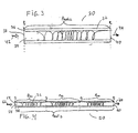
- a fourth embodiment of the chiral polarizer 30 is shown as a chiral polarizer 50.
- the chiral polarizer 50 is advantageously configured for working with linearly polarized incident light and is especially useful when optimization or "cleaning-up" of linearly polarized light is desired with an extremely desirable extinction ratio as well as a minimal insertion loss.
- the chiral polarizer 50 comprises a chiral fiber structure 52 having an outer cladding 56, an inner central core 54, an entry end 58, and a n exit end 60.
- the chiral fiber structure 52 has a pitch profile P prof-3 that includes two or more regions having individual pitch profiles configured as if multiple sequential chiral fiber structures 32 were formed as a single unit - i.e., the entry and exit ends of each region are configured with the inverse pitch being zero.
- FIG, 4 shows three such regions having respective pitch profiles P R1 , P R2 , and P R3 . It should be noted that the number of regions with individual pitch profiles that make up the pitch profile P prof-3 may be selected as a matter of design choice without departing from the spirit of the invention.
- incident light 62 having two linearly polarized orthogonal components enters the entry end 58, it is converted to elliptically polarized light and back to linearly polarized light, while simultaneously preserving the desired polarization component and scattering the undesirable polarization component, several times, once in each region, such that the emerging desirable linearly polarized light component 64 has minimal loss as compared to the incident light 62, and has a greatly optimized extinction ratio with respect to the scattered undesirable polarization component.
- the various inventive chiral polarizer embodiments shown in FIGS. 1-4 thus address all of the disadvantages of the previously known in-line polarizers because they: operate with optimized extinction ratios within desired spectral ranges, minimize the insertion loss in case of polarizers 30 and 50, are easy and inexpensive to fabricate, and do not change the size of the optical fiber in which they are used.
Landscapes
- Physics & Mathematics (AREA)
- General Physics & Mathematics (AREA)
- Optics & Photonics (AREA)
- Polarising Elements (AREA)
- Optical Couplings Of Light Guides (AREA)
- Optical Fibers, Optical Fiber Cores, And Optical Fiber Bundles (AREA)
Claims (26)
- Chiraler Polarisator zum Erreichen einer Polarisation von einfallendem Licht, wobei das einfallende Licht zwei orthogonal elliptisch polarisierte Komponenten einer ersten Exzentrizität hat, aufweisend:einen langgestreckten chiralen Lichtwellenleiter mit einer vorbestimmten Händigkeit, wobei der chirale Lichtwellenleiter ein erstes Ende, ein zweites Ende, einen Kern mit einem Kern-Brechungsindex und einer Kerngröße, der entlang der Längsachse des Leiters angeordnet ist, und eine Ummantelung mit einem Ummantelungs-Brechungsindex und einer Ummantelungsgröße, die den Kern umgibt, aufweist, wobei der chirale Lichtwellenleiter des Weiteren ein vorbestimmtes Steigungsprofil aufweist, das für eine Änderung einer Spiralsteigung P des chiralen Lichtwellenleiters zwischen dem ersten Ende und dem zweiten Ende repräsentativ ist, wobei gemäß dem vorbestimmten Steigungsprofil der chirale Lichtwellenleiter an dem ersten Ende mindestens eine orthogonal elliptisch polarisierte Lichtkomponente der beiden orthogonal elliptisch polarisierten Komponenten der ersten Exzentrizität unterstützt, wobei der chirale Lichtwellenleiter an dem zweiten Ende mindestens eine orthogonal elliptisch polarisierte Lichtkomponente einer zweiten Exzentrizität unterstützt, wobei zumindest ein Abschnitt des Steigungsprofils der neuen chiralen Faserstruktur zwischen dem ersten und dem zweiten Ende von dieser eine Spiralsteigung von einem ausreichend kurzen Wert aufweist, um eine polarisationsselektive Streuung zu bewirken, und wobei sich eine inverse Eintrittssteigung an dem ersten Ende wesentlich von einer inversen Austrittssteigung an dem zweiten Ende unterscheidet, so dass eine elliptisch polarisierte Komponente des einfallenden Lichts, das in das erste Ende eintritt, im Wesentlichen gestreut wird, während eine andere elliptisch polarisierte Komponente des einfallenden Lichts im Wesentlichen übertragen und in eine elliptisch polarisierte Austrittslichtkomponente umgewandelt wird, bei der sich die zweite Exzentrizität von der ersten Exzentrizität unterscheidet.
- Chiraler Polarisator nach Anspruch 1, wobei das vorbestimmte Steigungsprofil so ausgewählt und konfiguriert ist, dass die inverse Austrittssteigung im Wesentlichen gleich null ist, so dass die zweite Exzentrizität der elliptisch polarisierten Austrittslichtkomponente ausreichend hoch ist, wodurch eine linear polarisierte Austrittslichtkomponente erzeugt wird.
- Chiraler Polarisator nach Anspruch 1, der zur Verwendung mit einfallendem Licht konfiguriert ist, aufweisend einfallende Lichtkomponenten, wobei die erste Exzentrizität der einfallenden Lichtkomponenten ausreichend hoch ist, so dass die einfallenden Lichtkomponenten im Wesentlichen linear polarisiert sind, wobei das vorbestimmte Steigungsprofil so ausgewählt und konfiguriert ist, dass die inverse Eintrittssteigung im Wesentlichen gleich null ist.
- Chiraler Polarisator nach Anspruch 1, wobei das vorbestimmte Steigungsprofil so ausgewählt und konfiguriert ist, dass die inverse Eintrittssteigung größer ist als die inverse Austrittssteigung, so dass die zweite Exzentrizität höher ist als die erste Exzentrizität.
- Chiraler Polarisator nach Anspruch 1, wobei das vorbestimmte Steigungsprofil so ausgewählt und konfiguriert ist, dass die inverse Austrittssteigung größer ist als die inverse Eintrittssteigung, so dass die zweite Exzentrizität geringer ist als die erste Exzentrizität.
- Chiraler Polarisator nach Anspruch 1, der zur Verwendung mit einfallendem Licht konfiguriert ist, aufweisend einfallende Lichtkomponenten, wobei die erste Exzentrizität der einfallenden Lichtkomponenten ausreichend hoch ist, so dass die einfallenden Lichtkomponenten im Wesentlichen linear polarisiert sind, wobei das vorbestimmte Steigungsprofil so ausgewählt und konfiguriert ist, dass sowohl die inverse Eintritts- als auch die inverse Austrittssteigung im Wesentlichen gleich null sind, und wobei der Wert zwischen diesen größer ist, so dass die zweite Exzentrizität der elliptisch polarisierten Austrittslichtkomponente ausreichend hoch ist, wodurch eine linear polarisierte Austrittslichtkomponente erzeugt wird.
- Chiraler Polarisator nach Anspruch 1, wobei eine inverse Steigung durch einen Ausdruck 1/P bestimmt wird und wobei die inverse Steigung an dem zweiten Ende im Wesentlichen gleich null ist, und wobei die inverse Steigung in mindestens einem Bereich zwischen dem ersten und dem zweiten Ende auf mindestens einen vorbestimmten Wert über null erhöht wird, so dass das in das erste Ende eintretende einfallende Licht als eine erste Lichtkomponente, die in einer ersten vorbestimmten Ausrichtung innerhalb eines gewünschten vorbestimmten Spektralbereichs linear polarisiert ist, austritt, während eine zweite Lichtkomponente mit einer zweiten vorbestimmten linearen Polarisationsausrichtung im Wesentlichen gestreut wird.
- Chiraler Polarisator nach Anspruch 7, wobei mindestens eines von einer Querschnittsform des Kerns, der Kerngröße, dem Kern-Brechungsindex, der Ummantelungsgröße, dem Ummantelungs-Brechungsindex und dem vorbestimmten Steigungsprofil so ausgewählt und konfiguriert ist, dass ein gewünschtes Extinktionsverhältnis in einem gewünschten vorbestimmten Spektralbereich erreicht wird.
- Chiraler Polarisator nach Anspruch 7, wobei das vorbestimmte Steigungsprofil mindestens einen Steigungsbereich aufweist, der ausgewählt ist aus einer Gruppe von: einer chiralen langperiodischen Gittersteigung, einer einem nicht-resonanten Streuungsband entsprechenden Steigung, einem einem chiralen Chirp-Fasergitter entsprechenden Steigungsbereich, einem einem apodisierten chiralen Fasergitter entsprechenden Steigungsbereich, einer Zufalls-Steigungsvariation sowie einer Steigungsvariation, die gemäß mindestens einer vorbestimmten mathematischen Funktion bestimmt wird.
- Chiraler Polarisator nach Anspruch 7, wobei, wenn das einfallende Licht eine erste elliptisch polarisierte Lichtkomponente und eine zweite elliptisch polarisierte Lichtkomponente aufweist, der Polarisator die erste elliptisch polarisierte Lichtkomponente vor dem Austritt aus dem zweiten Ende im Wesentlichen in die erste linear polarisierte Lichtkomponente mit der ersten vorbestimmten Ausrichtung umwandelt und die zweite elliptisch polarisierte Lichtkomponente im Wesentlichen streut.
- Chiraler Polarisator nach Anspruch 10, wobei das vorbestimmte Steigungsprofil so ausgewählt ist, dass die Streuung der zweiten elliptisch polarisierten Lichtkomponente mit der Umwandlung der zweiten elliptisch polarisierten Lichtkomponente in die zweite linear polarisierte Lichtkomponente mit der zweiten vorbestimmten Ausrichtung synchronisiert wird.
- Chiraler Polarisator nach Anspruch 7, wobei die erste vorbestimmte Ausrichtung im Wesentlichen senkrecht zur zweiten vorbestimmten Ausrichtung ist.
- Chiraler Polarisator nach Anspruch 7, der zur Verwendung mit einfallendem Licht konfiguriert ist, aufweisend einfallende Lichtkomponenten, wobei das einfallende Licht eine erste linear polarisierte einfallende Lichtkomponente und eine zweite linear polarisierte einfallende Lichtkomponente aufweist, wobei das vorbestimmte Steigungsprofil so ausgewählt und konfiguriert ist, dass die inverse Steigung an dem ersten Ende im Wesentlichen gleich null ist, wodurch der Einfügungsverlust für die erste linear polarisierte Lichtkomponente innerhalb des gewünschten Spektralbereichs minimiert wird.
- Chiraler Polarisator nach Anspruch 13, wobei mindestens eines von einer Querschnittsform des Kerns, der Kerngröße, dem Kern-Brechungsindex, der Ummantelungsgröße, dem Ummantelungs-Brechungsindex und dem vorbestimmten Steigungsprofil so ausgewählt und konfiguriert ist, dass das gewünschte Extinktionsverhältnis in dem gewünschten vorbestimmten Spektralbereich erreicht wird, während der Einfügungsverlust minimiert wird.
- Chiraler Polarisator nach Anspruch 13, wobei das Steigungsprofil so ausgewählt und konfiguriert ist, dass, wenn sie in das erste Ende eintritt, die erste linear polarisierte Lichtkomponente in eine erste elliptisch polarisierte Lichtkomponente umgewandelt wird, und die zweite linear polarisierte einfallende Lichtkomponente in eine zweite elliptisch polarisierte Lichtkomponente umgewandelt wird, wobei vor dem Austritt aus dem zweiten Ende die erste elliptisch polarisierte Lichtkomponente im Wesentlichen in die erste linear polarisierte Lichtkomponente mit der ersten vorbestimmten Ausrichtung umgewandelt wird und die zweite elliptisch polarisierte Lichtkomponente im Wesentlichen gestreut wird.
- Chiraler Polarisator nach Anspruch 15, wobei das vorbestimmte Steigungsprofil so ausgewählt ist, dass die Streuung der zweiten elliptisch polarisierten Lichtkomponente mit der Umwandlung der zweiten linear polarisierten einfallenden Lichtkomponente in die zweite elliptisch polarisierte Lichtkomponente und der anschließenden Umwandlung der zweiten elliptisch polarisierten Lichtkomponente in die zweite linear polarisierte Lichtkomponente mit der zweiten vorbestimmten Ausrichtung synchronisiert wird.
- Chiraler Polarisator nach Anspruch 13, ferner aufweisend mindestens einen zusätzlichen chiralen Lichtwellenleiter, die in Kontakt zueinander entlang der Längsachse des chiralen Lichtwellenleiters aufeinanderfolgend positioniert sind, wobei diese jeweils ein besonderes entsprechendes Steigungsprofil und jeweils einen inversen Steigungswert an ihrem Eintrittsende und an ihrem Austrittsende im Wesentlichen gleich null aufweisen, wodurch ein Extinktionsverhältnis in Bezug auf die gestreute zweite linear polarisierte Lichtkomponente optimiert wird.
- Verfahren zum Erreichen einer Polarisation von einfallendem Licht in einem chiralen Polarisator, aufweisend die folgenden Schritte:(a)Vorsehen eines langgestreckten chiralen Lichtwellenleiters mit einer vorbestimmten Händigkeit, wobei der chirale Lichtwellenleiter ein erstes Ende, ein zweites Ende, einen Kern mit einem Kern-Brechungsindex und einer Kerngröße, der entlang der Längsachse des Leiters angeordnet ist, und eine Ummantelung mit einem Ummantelungs-Brechungsindex und einer Ummantelungsgröße, die den Kern umgibt, aufweist, und(b)Auswählen, Konfigurieren und Anwenden auf den chiralen Lichtwellenleiter eines vorbestimmten Steigungsprofils, das für eine Änderung einer Steigung P des chiralen Lichtwellenleiters zwischen dem ersten Ende und dem zweiten Ende repräsentativ ist, wobei eine inverse Steigung durch einen Ausdruck 1/P bestimmt wird, wobei die inverse Steigung gemäß dem vorbestimmten Steigungsprofil an dem zweiten Ende im Wesentlichen gleich null ist und wobei die inverse Steigung in mindestens einem Bereich zwischen dem ersten und dem zweiten Ende auf mindestens einen vorbestimmten Wert über null erhöht wird, so dass das in das erste Ende eintretende einfallende Licht als eine erste Lichtkomponente austritt, die in einer ersten vorbestimmten Ausrichtung innerhalb eines gewünschten vorbestimmten Spektralbereichs linear polarisiert ist, während eine zweite Lichtkomponente mit einer zweiten vorbestimmten linearen Polarisationsausrichtung im Wesentlichen gestreut wird.
- Chiraler Polarisator nach Anspruch 1 zum Verbessern eines Extinktionsverhältnisses von einfallendem Licht mit einer ersten und einer zweiten linear polarisierten einfallenden Lichtkomponente, wobei der Einfügungsverlust von dieser minimiert wird, wobei eine inverse Steigung durch einen Ausdruck 1/P bestimmt wird und wobei die inverse Steigung an jedem des ersten und des zweiten Endes im Wesentlichen gleich null ist, und wobei die inverse Steigung in mindestens einem Bereich zwischen dem ersten und dem zweiten Ende auf mindestens einen vorbestimmten Wert über null erhöht wird, so dass von der ersten und der zweiten linear polarisierten einfallenden Lichtkomponente, die in das erste Ende eintreten, nur eine erste Austrittslichtkomponente, die in einer ersten vorbestimmten Ausrichtung innerhalb des gewünschten vorbestimmten Spektralbereiches linear polarisiert ist, mit minimiertem Einfügungsverlust austritt, während eine zweite Austrittslichtkomponente mit einer zweiten vorbestimmten linearen Polarisationsausrichtung im Wesentlichen gemäß dem gewünschten Extinktionsverhältnis gestreut wird.
- Chiraler Polarisator nach Anspruch 1 zum Erreichen der Polarisation von einfallendem Licht, wobei eine inverse Steigung durch einen Ausdruck 1/P bestimmt wird, und wobei eine inverse Steigung an dem ersten Ende größer ist als eine zweite inverse Steigung an dem zweiten Ende, und wobei die inverse Steigung in mindestens einem Bereich zwischen dem ersten und dem zweiten Ende auf mindestens einen vorbestimmten Wert über null erhöht wird, so dass das in das erste Ende eintretende einfallende Licht als eine erste Lichtkomponente, die in einer ersten vorbestimmten Ausrichtung mit einer zur Struktur-Händigkeit entgegengesetzten Händigkeit innerhalb eines gewünschten vorbestimmten Spektralbereichs elliptisch polarisiert wird, während eine zweite Lichtkomponente mit einer zweiten vorbestimmten elliptischen Polarisationsausrichtung im Wesentlichen gestreut wird.
- Chiraler Polarisator nach Anspruch 20, wobei mindestens eines von einer Querschnittsform des Kerns, der Kerngröße, dem Kern-Brechungsindex, der Ummantelungsgröße, dem Ummantelungs-Brechungsindex und dem vorbestimmten Steigungsprofil so ausgewählt und konfiguriert ist, dass das gewünschte Extinktionsverhältnis in dem gewünschten vorbestimmten Spektralbereich erreicht wird.
- Chiraler Polarisator nach Anspruch 20, wobei das vorbestimmte Steigungsprofil mindestens einen Steigungsbereich aufweist, der ausgewählt ist aus: einer chiralen langperiodischen Gittersteigung, einer einem nicht-resonanten Streuungsband entsprechenden Steigung, einem einem chiralen Chirp-Fasergitter entsprechenden Steigungsbereich, einem einem apodisierten chiralen Fasergitter entsprechenden Steigungsbereich, einer Zufalls-Steigungsvariation sowie einer Steigungsvariation, die gemäß mindestens einer vorbestimmten mathematischen Funktion bestimmt wird
- Chiraler Polarisator nach Anspruch 20, wobei die zweite inverse Steigung im Wesentlichen gleich null ist.
- Chiraler Polarisator nach Anspruch 22, wobei das vorbestimmte Steigungsprofil so ausgewählt und konfiguriert ist, dass die inverse Steigung an dem ersten Ende im Wesentlichen gleich null ist, so dass der Einfügungsverlust für die erste linear polarisierte Lichtkomponente innerhalb des gewünschten Spektralbereichs minimiert wird.
- Chiraler Polarisator nach Anspruch 1 zum Erreichen der Polarisation von einfallendem Licht mit einer ersten und einer zweiten kreisförmig polarisierten einfallenden Lichtkomponente, wobei eine inverse Steigung durch einen Ausdruck 1/P bestimmt wird, und wobei eine erste inverse Steigung an dem ersten Ende größer ist als eine zweite inverse Steigung an dem zweiten Ende, und wobei die inverse Steigung in mindestens einem Bereich zwischen dem ersten und dem zweiten Ende auf mindestens einen vorbestimmten Wert über null erhöht wird, so dass von der ersten und der zweiten kreisförmig polarisierten einfallenden Lichtkomponente, die in das erste Ende eintreten, nur eine erste Austrittslichtkomponente, die in einer ersten vorbestimmten Ausrichtung innerhalb des gewünschten vorbestimmten Spektralbereichs linear polarisiert ist, austritt, während eine zweite Austrittslichtkomponente mit einer zweiten vorbestimmten elliptischen Polarisationsausrichtung im Wesentlichen gestreut wird.
- Chiraler Polarisator nach Anspruch 1 zum Erreichen der Polarisation von einfallendem Licht mit einer ersten und einer zweiten linear polarisierten einfallenden Lichtkomponente, wobei eine inverse Steigung durch einen Ausdruck 1/P bestimmt wird, und wobei die inverse Steigung an dem ersten Ende im Wesentlichen gleich null ist, und wobei die inverse Steigung in mindestens einem Bereich zwischen dem ersten und dem zweiten Ende auf mindestens einen vorbestimmten Wert über null erhöht wird, so dass die in das erste Ende eintretende erste linear polarisierte einfallende Lichtkomponente als eine erste Austrittslichtkomponente, die in einer ersten vorbestimmten Ausrichtung innerhalb eines gewünschten vorbestimmten Spektralbereichs linear polarisiert ist, austritt, während die zweite linear polarisierte einfallende Lichtkomponente im Wesentlichen gestreut wird.
Applications Claiming Priority (2)
| Application Number | Priority Date | Filing Date | Title |
|---|---|---|---|
| US51445904P | 2004-10-24 | 2004-10-24 | |
| PCT/US2004/035225 WO2006046947A2 (en) | 2004-10-24 | 2004-10-25 | Chiral in-fiber polarizer apparatus and method |
Publications (3)
| Publication Number | Publication Date |
|---|---|
| EP1803005A2 EP1803005A2 (de) | 2007-07-04 |
| EP1803005A4 EP1803005A4 (de) | 2009-10-28 |
| EP1803005B1 true EP1803005B1 (de) | 2012-09-26 |
Family
ID=36228186
Family Applications (1)
| Application Number | Title | Priority Date | Filing Date |
|---|---|---|---|
| EP04796253A Expired - Lifetime EP1803005B1 (de) | 2004-10-24 | 2004-10-25 | Chirale faserinterne polarisierervorrichtung und verfahren |
Country Status (5)
| Country | Link |
|---|---|
| EP (1) | EP1803005B1 (de) |
| JP (1) | JP2008524637A (de) |
| CN (1) | CN100480749C (de) |
| CA (1) | CA2585241A1 (de) |
| WO (1) | WO2006046947A2 (de) |
Families Citing this family (30)
| Publication number | Priority date | Publication date | Assignee | Title |
|---|---|---|---|---|
| EP2313802A4 (de) | 2008-06-26 | 2011-08-03 | Chiral Photonics Inc | Optischer chiralfaserisolator und herstellungsverfahren dafür |
| US9766407B2 (en) | 2008-07-14 | 2017-09-19 | Chiral Photonics, Inc. | Untappable secure optical fiber link component |
| US20130216184A1 (en) | 2008-07-14 | 2013-08-22 | Victor Il'ich Kopp | Configurable pitch reducing optical fiber array |
| US9851510B2 (en) | 2008-07-14 | 2017-12-26 | Chiral Photonics, Inc. | Phase locking optical fiber coupler |
| US9857536B2 (en) | 2008-07-14 | 2018-01-02 | Chiral Photonics, Inc. | Optical component assembly for use with an optical device |
| WO2010071861A2 (en) | 2008-12-18 | 2010-06-24 | Chiral Photonics, Inc. | Fiber optic diffraction grating |
| US20110292676A1 (en) | 2010-05-28 | 2011-12-01 | Etkin | Chiral Fiber Apparatus and Method for Controllable Light Extraction from Optical Waveguides |
| US10502898B2 (en) | 2011-01-20 | 2019-12-10 | Chiral Photonics, Inc. | Chiral fiber circular polarizer |
| US20120257857A1 (en) | 2011-04-08 | 2012-10-11 | Chiral Photonics, Inc. | High Density Optical Packaging Header Apparatus |
| US20130188175A1 (en) | 2012-01-20 | 2013-07-25 | Chiral Photonics, Inc. | Configurable Chiral Fiber Tip-Positioned Sensor |
| US10914891B2 (en) | 2013-06-14 | 2021-02-09 | Chiral Photonics, Inc. | Multichannel optical coupler |
| US9817191B2 (en) | 2013-06-14 | 2017-11-14 | Chiral Photonics, Inc. | Multichannel optical coupler array |
| US10838155B2 (en) | 2013-06-14 | 2020-11-17 | Chiral Photonics, Inc. | Multichannel optical coupler |
| US10126494B2 (en) | 2013-06-14 | 2018-11-13 | Chiral Photonics, Inc. | Configurable polarization mode coupler |
| US10101536B2 (en) | 2013-06-14 | 2018-10-16 | Chiral Photonics, Inc. | Multichannel optical coupler array |
| US11966091B2 (en) | 2013-06-14 | 2024-04-23 | Chiral Photonics, Inc. | Multichannel optical coupler array |
| US10564348B2 (en) | 2013-06-14 | 2020-02-18 | Chiral Photonics, Inc. | Passive aligning optical coupler array |
| US11156781B2 (en) | 2013-06-14 | 2021-10-26 | Chiral Photonics, Inc. | Passive aligning optical coupler array |
| US9810845B2 (en) | 2015-09-22 | 2017-11-07 | Chiral Photonics, Inc. | Flexible optical fiber array |
| EP3387471B1 (de) | 2015-12-09 | 2022-05-04 | Chiral Photonics, Inc. | Polarisationserhaltendes glasfaserarray |
| US9885825B2 (en) | 2016-04-18 | 2018-02-06 | Chiral Photonics, Inc. | Pitch reducing optical fiber array and multicore fiber comprising at least one chiral fiber grating |
| US10429584B2 (en) * | 2016-11-22 | 2019-10-01 | Lumentum Operations Llc | Rotary optical beam generator |
| CN108333675A (zh) * | 2018-02-27 | 2018-07-27 | 长飞光纤光缆股份有限公司 | 一种手征性耦合纤芯增益光纤及制备方法 |
| JP7182250B2 (ja) * | 2018-08-27 | 2022-12-02 | 国立大学法人静岡大学 | 多チャンネルファイバグレーティング、及び多チャンネルファイバグレーティングの製造方法 |
| US11022762B2 (en) | 2019-08-05 | 2021-06-01 | Chiral Photonics, Inc. | Optical fiber connectors for rotational alignment |
| CN110487755B (zh) * | 2019-08-06 | 2021-10-26 | 电子科技大学 | 基于长周期光纤光栅手征参数和折射率同时检测的方法 |
| CN114008498A (zh) * | 2019-08-30 | 2022-02-01 | 南洋理工大学 | 光纤、具有该光纤的照明设备以及用于形成该光纤的方法 |
| US12210185B2 (en) | 2020-02-24 | 2025-01-28 | Chiral Photonics, Inc. | Wavelength division multiplexers for space division multiplexing (SDM-WDM devices) |
| US11609376B2 (en) | 2020-02-24 | 2023-03-21 | Chiral Photonics, Inc. | Space division multiplexers |
| CN115561857B (zh) * | 2022-10-17 | 2025-08-01 | 中国科学技术大学 | 一种横截面非圆对称的手征光纤光栅 |
Citations (1)
| Publication number | Priority date | Publication date | Assignee | Title |
|---|---|---|---|---|
| US20030118265A1 (en) * | 2001-12-06 | 2003-06-26 | Kopp Victor Il?Apos;Ich | Chiral in-fiber adjustable polarizer apparatus and method |
Family Cites Families (6)
| Publication number | Priority date | Publication date | Assignee | Title |
|---|---|---|---|---|
| US5298047A (en) * | 1992-08-03 | 1994-03-29 | At&T Bell Laboratories | Method of making a fiber having low polarization mode dispersion due to a permanent spin |
| JP3226283B2 (ja) * | 1996-01-22 | 2001-11-05 | コーニング インコーポレイテッド | 偏光モード分散を減少させるためにスピンを変調させた光ファイバ並びにその製造方法および装置 |
| US6169830B1 (en) * | 1996-08-26 | 2001-01-02 | Arroyo Optics, Inc. | Methods of fabricating grating assisted coupler devices |
| DE19729817A1 (de) * | 1997-07-11 | 1999-01-14 | Basf Ag | Polymerisation von Cyclopentadien mit kationischen Palladium-Komplexen |
| US6271952B1 (en) * | 1998-08-18 | 2001-08-07 | Nortel Networks Limited | Polarization mode dispersion compensation |
| US6920270B2 (en) * | 2000-07-06 | 2005-07-19 | Pirelli Cavi E Sistemi S.P.A. | Optical fibre with reduced polarization mode dispersion and method for obtaining an optical fibre with reduced polarization mode dispersion |
-
2004
- 2004-10-25 EP EP04796253A patent/EP1803005B1/de not_active Expired - Lifetime
- 2004-10-25 CA CA002585241A patent/CA2585241A1/en not_active Abandoned
- 2004-10-25 CN CNB200480038876XA patent/CN100480749C/zh not_active Expired - Fee Related
- 2004-10-25 WO PCT/US2004/035225 patent/WO2006046947A2/en not_active Ceased
- 2004-10-25 JP JP2007537863A patent/JP2008524637A/ja active Pending
Patent Citations (1)
| Publication number | Priority date | Publication date | Assignee | Title |
|---|---|---|---|---|
| US20030118265A1 (en) * | 2001-12-06 | 2003-06-26 | Kopp Victor Il?Apos;Ich | Chiral in-fiber adjustable polarizer apparatus and method |
Also Published As
| Publication number | Publication date |
|---|---|
| EP1803005A2 (de) | 2007-07-04 |
| CN1898586A (zh) | 2007-01-17 |
| WO2006046947A2 (en) | 2006-05-04 |
| WO2006046947A3 (en) | 2006-06-01 |
| CA2585241A1 (en) | 2006-05-04 |
| CN100480749C (zh) | 2009-04-22 |
| EP1803005A4 (de) | 2009-10-28 |
| JP2008524637A (ja) | 2008-07-10 |
Similar Documents
| Publication | Publication Date | Title |
|---|---|---|
| EP1803005B1 (de) | Chirale faserinterne polarisierervorrichtung und verfahren | |
| US7095911B2 (en) | Chiral in-fiber polarizer apparatus and method | |
| US6721469B2 (en) | Chiral in-fiber adjustable polarizer apparatus and method | |
| US8463094B2 (en) | Chiral fiber polarizer | |
| US7983515B2 (en) | Polarization maintaining optical fiber polarizer | |
| US7463800B2 (en) | Chiral fiber grating device and method of fabrication thereof | |
| US6839486B2 (en) | Chiral fiber grating | |
| US6741631B2 (en) | Customizable apodized chiral fiber grating apparatus and method | |
| WO2008080174A1 (en) | Single helix chiral fiber grating | |
| US20030118285A1 (en) | Customizable chirped chiral fiber bragg grating | |
| EP2478400B1 (de) | Transversalmodenfilter für wellenleiter | |
| Ivanov | Wavelength shift and split of cladding mode resonances in microbend long-period fiber gratings under torsion | |
| CN217766906U (zh) | 一种超宽带平坦的全光纤型圆起偏器 | |
| CN110244407A (zh) | 一种全光纤双折射滤波器 | |
| EP1395870B1 (de) | Optischer braggfasergitter-polarisator | |
| KR100422197B1 (ko) | 나선형 광섬유격자 제작장치 | |
| EP2764386B1 (de) | Faserentwürfe für ultrakurze pulslaser mit abstimmbarer wellenlänge | |
| CN119376116A (zh) | 一种光纤型可调谐圆偏振光转换器件及其制作方法 | |
| Shin et al. | Bandwidth tunable band rejection filter based on helicoidal fiber grating pair of opposite hellicity |
Legal Events
| Date | Code | Title | Description |
|---|---|---|---|
| PUAI | Public reference made under article 153(3) epc to a published international application that has entered the european phase |
Free format text: ORIGINAL CODE: 0009012 |
|
| 17P | Request for examination filed |
Effective date: 20060524 |
|
| AK | Designated contracting states |
Kind code of ref document: A2 Designated state(s): AT BE BG CH CY CZ DE DK EE ES FI FR GB GR HU IE IT LI LU MC NL PL PT RO SE SI SK TR |
|
| DAX | Request for extension of the european patent (deleted) | ||
| A4 | Supplementary search report drawn up and despatched |
Effective date: 20090930 |
|
| 17Q | First examination report despatched |
Effective date: 20101130 |
|
| REG | Reference to a national code |
Ref country code: DE Ref legal event code: R079 Ref document number: 602004039489 Country of ref document: DE Free format text: PREVIOUS MAIN CLASS: G02B0006000000 Ipc: G02B0006100000 |
|
| GRAP | Despatch of communication of intention to grant a patent |
Free format text: ORIGINAL CODE: EPIDOSNIGR1 |
|
| RIC1 | Information provided on ipc code assigned before grant |
Ipc: G02B 6/10 20060101AFI20120124BHEP Ipc: G02B 6/02 20060101ALI20120124BHEP |
|
| GRAS | Grant fee paid |
Free format text: ORIGINAL CODE: EPIDOSNIGR3 |
|
| RAP1 | Party data changed (applicant data changed or rights of an application transferred) |
Owner name: CHIRAL PHOTONICS, INC. |
|
| GRAA | (expected) grant |
Free format text: ORIGINAL CODE: 0009210 |
|
| AK | Designated contracting states |
Kind code of ref document: B1 Designated state(s): AT BE BG CH CY CZ DE DK EE ES FI FR GB GR HU IE IT LI LU MC NL PL PT RO SE SI SK TR |
|
| RAP1 | Party data changed (applicant data changed or rights of an application transferred) |
Owner name: CHIRAL PHOTONICS, INC. |
|
| REG | Reference to a national code |
Ref country code: GB Ref legal event code: FG4D |
|
| REG | Reference to a national code |
Ref country code: CH Ref legal event code: EP |
|
| REG | Reference to a national code |
Ref country code: AT Ref legal event code: REF Ref document number: 577297 Country of ref document: AT Kind code of ref document: T Effective date: 20121015 |
|
| REG | Reference to a national code |
Ref country code: IE Ref legal event code: FG4D |
|
| REG | Reference to a national code |
Ref country code: DE Ref legal event code: R096 Ref document number: 602004039489 Country of ref document: DE Effective date: 20121122 |
|
| PG25 | Lapsed in a contracting state [announced via postgrant information from national office to epo] |
Ref country code: FI Free format text: LAPSE BECAUSE OF FAILURE TO SUBMIT A TRANSLATION OF THE DESCRIPTION OR TO PAY THE FEE WITHIN THE PRESCRIBED TIME-LIMIT Effective date: 20120926 |
|
| REG | Reference to a national code |
Ref country code: AT Ref legal event code: MK05 Ref document number: 577297 Country of ref document: AT Kind code of ref document: T Effective date: 20120926 |
|
| REG | Reference to a national code |
Ref country code: NL Ref legal event code: VDEP Effective date: 20120926 |
|
| PG25 | Lapsed in a contracting state [announced via postgrant information from national office to epo] |
Ref country code: SI Free format text: LAPSE BECAUSE OF FAILURE TO SUBMIT A TRANSLATION OF THE DESCRIPTION OR TO PAY THE FEE WITHIN THE PRESCRIBED TIME-LIMIT Effective date: 20120926 Ref country code: GR Free format text: LAPSE BECAUSE OF FAILURE TO SUBMIT A TRANSLATION OF THE DESCRIPTION OR TO PAY THE FEE WITHIN THE PRESCRIBED TIME-LIMIT Effective date: 20121227 Ref country code: SE Free format text: LAPSE BECAUSE OF FAILURE TO SUBMIT A TRANSLATION OF THE DESCRIPTION OR TO PAY THE FEE WITHIN THE PRESCRIBED TIME-LIMIT Effective date: 20120926 |
|
| PGFP | Annual fee paid to national office [announced via postgrant information from national office to epo] |
Ref country code: GB Payment date: 20121031 Year of fee payment: 9 |
|
| PG25 | Lapsed in a contracting state [announced via postgrant information from national office to epo] |
Ref country code: EE Free format text: LAPSE BECAUSE OF FAILURE TO SUBMIT A TRANSLATION OF THE DESCRIPTION OR TO PAY THE FEE WITHIN THE PRESCRIBED TIME-LIMIT Effective date: 20120926 Ref country code: ES Free format text: LAPSE BECAUSE OF FAILURE TO SUBMIT A TRANSLATION OF THE DESCRIPTION OR TO PAY THE FEE WITHIN THE PRESCRIBED TIME-LIMIT Effective date: 20130106 Ref country code: BE Free format text: LAPSE BECAUSE OF FAILURE TO SUBMIT A TRANSLATION OF THE DESCRIPTION OR TO PAY THE FEE WITHIN THE PRESCRIBED TIME-LIMIT Effective date: 20120926 Ref country code: RO Free format text: LAPSE BECAUSE OF FAILURE TO SUBMIT A TRANSLATION OF THE DESCRIPTION OR TO PAY THE FEE WITHIN THE PRESCRIBED TIME-LIMIT Effective date: 20120926 Ref country code: CZ Free format text: LAPSE BECAUSE OF FAILURE TO SUBMIT A TRANSLATION OF THE DESCRIPTION OR TO PAY THE FEE WITHIN THE PRESCRIBED TIME-LIMIT Effective date: 20120926 Ref country code: NL Free format text: LAPSE BECAUSE OF FAILURE TO SUBMIT A TRANSLATION OF THE DESCRIPTION OR TO PAY THE FEE WITHIN THE PRESCRIBED TIME-LIMIT Effective date: 20120926 |
|
| PGFP | Annual fee paid to national office [announced via postgrant information from national office to epo] |
Ref country code: DE Payment date: 20121228 Year of fee payment: 9 |
|
| PG25 | Lapsed in a contracting state [announced via postgrant information from national office to epo] |
Ref country code: CY Free format text: LAPSE BECAUSE OF FAILURE TO SUBMIT A TRANSLATION OF THE DESCRIPTION OR TO PAY THE FEE WITHIN THE PRESCRIBED TIME-LIMIT Effective date: 20120926 Ref country code: PT Free format text: LAPSE BECAUSE OF FAILURE TO SUBMIT A TRANSLATION OF THE DESCRIPTION OR TO PAY THE FEE WITHIN THE PRESCRIBED TIME-LIMIT Effective date: 20130128 Ref country code: SK Free format text: LAPSE BECAUSE OF FAILURE TO SUBMIT A TRANSLATION OF THE DESCRIPTION OR TO PAY THE FEE WITHIN THE PRESCRIBED TIME-LIMIT Effective date: 20120926 Ref country code: PL Free format text: LAPSE BECAUSE OF FAILURE TO SUBMIT A TRANSLATION OF THE DESCRIPTION OR TO PAY THE FEE WITHIN THE PRESCRIBED TIME-LIMIT Effective date: 20120926 Ref country code: MC Free format text: LAPSE BECAUSE OF NON-PAYMENT OF DUE FEES Effective date: 20121031 |
|
| REG | Reference to a national code |
Ref country code: CH Ref legal event code: PL |
|
| PG25 | Lapsed in a contracting state [announced via postgrant information from national office to epo] |
Ref country code: AT Free format text: LAPSE BECAUSE OF FAILURE TO SUBMIT A TRANSLATION OF THE DESCRIPTION OR TO PAY THE FEE WITHIN THE PRESCRIBED TIME-LIMIT Effective date: 20120926 |
|
| REG | Reference to a national code |
Ref country code: IE Ref legal event code: MM4A |
|
| PG25 | Lapsed in a contracting state [announced via postgrant information from national office to epo] |
Ref country code: CH Free format text: LAPSE BECAUSE OF NON-PAYMENT OF DUE FEES Effective date: 20121031 Ref country code: LI Free format text: LAPSE BECAUSE OF NON-PAYMENT OF DUE FEES Effective date: 20121031 Ref country code: IE Free format text: LAPSE BECAUSE OF NON-PAYMENT OF DUE FEES Effective date: 20121025 Ref country code: DK Free format text: LAPSE BECAUSE OF FAILURE TO SUBMIT A TRANSLATION OF THE DESCRIPTION OR TO PAY THE FEE WITHIN THE PRESCRIBED TIME-LIMIT Effective date: 20120926 Ref country code: BG Free format text: LAPSE BECAUSE OF FAILURE TO SUBMIT A TRANSLATION OF THE DESCRIPTION OR TO PAY THE FEE WITHIN THE PRESCRIBED TIME-LIMIT Effective date: 20121226 |
|
| PLBE | No opposition filed within time limit |
Free format text: ORIGINAL CODE: 0009261 |
|
| STAA | Information on the status of an ep patent application or granted ep patent |
Free format text: STATUS: NO OPPOSITION FILED WITHIN TIME LIMIT |
|
| PG25 | Lapsed in a contracting state [announced via postgrant information from national office to epo] |
Ref country code: IT Free format text: LAPSE BECAUSE OF FAILURE TO SUBMIT A TRANSLATION OF THE DESCRIPTION OR TO PAY THE FEE WITHIN THE PRESCRIBED TIME-LIMIT Effective date: 20120926 |
|
| 26N | No opposition filed |
Effective date: 20130627 |
|
| REG | Reference to a national code |
Ref country code: FR Ref legal event code: ST Effective date: 20130805 |
|
| REG | Reference to a national code |
Ref country code: DE Ref legal event code: R097 Ref document number: 602004039489 Country of ref document: DE Effective date: 20130627 |
|
| PG25 | Lapsed in a contracting state [announced via postgrant information from national office to epo] |
Ref country code: FR Free format text: LAPSE BECAUSE OF NON-PAYMENT OF DUE FEES Effective date: 20121126 |
|
| PG25 | Lapsed in a contracting state [announced via postgrant information from national office to epo] |
Ref country code: TR Free format text: LAPSE BECAUSE OF FAILURE TO SUBMIT A TRANSLATION OF THE DESCRIPTION OR TO PAY THE FEE WITHIN THE PRESCRIBED TIME-LIMIT Effective date: 20120926 |
|
| PG25 | Lapsed in a contracting state [announced via postgrant information from national office to epo] |
Ref country code: LU Free format text: LAPSE BECAUSE OF NON-PAYMENT OF DUE FEES Effective date: 20121025 |
|
| GBPC | Gb: european patent ceased through non-payment of renewal fee |
Effective date: 20131025 |
|
| PG25 | Lapsed in a contracting state [announced via postgrant information from national office to epo] |
Ref country code: HU Free format text: LAPSE BECAUSE OF FAILURE TO SUBMIT A TRANSLATION OF THE DESCRIPTION OR TO PAY THE FEE WITHIN THE PRESCRIBED TIME-LIMIT Effective date: 20041025 Ref country code: GB Free format text: LAPSE BECAUSE OF NON-PAYMENT OF DUE FEES Effective date: 20131025 |
|
| REG | Reference to a national code |
Ref country code: DE Ref legal event code: R119 Ref document number: 602004039489 Country of ref document: DE Effective date: 20140501 |
|
| PG25 | Lapsed in a contracting state [announced via postgrant information from national office to epo] |
Ref country code: DE Free format text: LAPSE BECAUSE OF NON-PAYMENT OF DUE FEES Effective date: 20140501 |