EP1803120B1 - Procede de reproduction, appareil de disque optique, programme et support d'enregistrement a informations lisibles par un ordinateur pour effectuer un saut de couche sur un disque optique multicouche - Google Patents
Procede de reproduction, appareil de disque optique, programme et support d'enregistrement a informations lisibles par un ordinateur pour effectuer un saut de couche sur un disque optique multicouche Download PDFInfo
- Publication number
- EP1803120B1 EP1803120B1 EP05795314.3A EP05795314A EP1803120B1 EP 1803120 B1 EP1803120 B1 EP 1803120B1 EP 05795314 A EP05795314 A EP 05795314A EP 1803120 B1 EP1803120 B1 EP 1803120B1
- Authority
- EP
- European Patent Office
- Prior art keywords
- address
- recording layer
- optical disk
- scanning path
- zone
- Prior art date
- Legal status (The legal status is an assumption and is not a legal conclusion. Google has not performed a legal analysis and makes no representation as to the accuracy of the status listed.)
- Expired - Lifetime
Links
Images


Classifications
-
- G—PHYSICS
- G11—INFORMATION STORAGE
- G11B—INFORMATION STORAGE BASED ON RELATIVE MOVEMENT BETWEEN RECORD CARRIER AND TRANSDUCER
- G11B27/00—Editing; Indexing; Addressing; Timing or synchronising; Monitoring; Measuring tape travel
- G11B27/10—Indexing; Addressing; Timing or synchronising; Measuring tape travel
- G11B27/102—Programmed access in sequence to addressed parts of tracks of operating record carriers
- G11B27/105—Programmed access in sequence to addressed parts of tracks of operating record carriers of operating discs
-
- G—PHYSICS
- G11—INFORMATION STORAGE
- G11B—INFORMATION STORAGE BASED ON RELATIVE MOVEMENT BETWEEN RECORD CARRIER AND TRANSDUCER
- G11B7/00—Recording or reproducing by optical means, e.g. recording using a thermal beam of optical radiation by modifying optical properties or the physical structure, reproducing using an optical beam at lower power by sensing optical properties; Record carriers therefor
- G11B7/08—Disposition or mounting of heads or light sources relatively to record carriers
- G11B7/085—Disposition or mounting of heads or light sources relatively to record carriers with provision for moving the light beam into, or out of, its operative position or across tracks, otherwise than during the transducing operation, e.g. for adjustment or preliminary positioning or track change or selection
- G11B7/08505—Methods for track change, selection or preliminary positioning by moving the head
- G11B7/08511—Methods for track change, selection or preliminary positioning by moving the head with focus pull-in only
-
- G—PHYSICS
- G11—INFORMATION STORAGE
- G11B—INFORMATION STORAGE BASED ON RELATIVE MOVEMENT BETWEEN RECORD CARRIER AND TRANSDUCER
- G11B7/00—Recording or reproducing by optical means, e.g. recording using a thermal beam of optical radiation by modifying optical properties or the physical structure, reproducing using an optical beam at lower power by sensing optical properties; Record carriers therefor
- G11B7/08—Disposition or mounting of heads or light sources relatively to record carriers
- G11B7/085—Disposition or mounting of heads or light sources relatively to record carriers with provision for moving the light beam into, or out of, its operative position or across tracks, otherwise than during the transducing operation, e.g. for adjustment or preliminary positioning or track change or selection
- G11B7/08505—Methods for track change, selection or preliminary positioning by moving the head
- G11B7/08517—Methods for track change, selection or preliminary positioning by moving the head with tracking pull-in only
-
- G—PHYSICS
- G11—INFORMATION STORAGE
- G11B—INFORMATION STORAGE BASED ON RELATIVE MOVEMENT BETWEEN RECORD CARRIER AND TRANSDUCER
- G11B7/00—Recording or reproducing by optical means, e.g. recording using a thermal beam of optical radiation by modifying optical properties or the physical structure, reproducing using an optical beam at lower power by sensing optical properties; Record carriers therefor
- G11B2007/0003—Recording, reproducing or erasing systems characterised by the structure or type of the carrier
- G11B2007/0009—Recording, reproducing or erasing systems characterised by the structure or type of the carrier for carriers having data stored in three dimensions, e.g. volume storage
- G11B2007/0013—Recording, reproducing or erasing systems characterised by the structure or type of the carrier for carriers having data stored in three dimensions, e.g. volume storage for carriers having multiple discrete layers
Definitions
- the present invention relates to a reproducing method, an optical disk apparatus, a program and a computer readable information recording medium, and further, to a reproducing method for reproducing information recorded in an optical disk having a plurality of recording layers, an optical disk apparatus for reproducing information recorded in an optical disk having a plurality of recording layers, a program applied in the optical disk apparatus and a computer readable information recording medium storing the program.
- an optical disk such as a DVD (digital versatile disk) has been taking attention, and, an optical disk apparatus for reproducing information from such an optical disk has spread in the market along with a price reduction thereof.
- An information amount of contents to process tends to increase year by year, and thereby, increase in a recording capacity in such an optical disk has been demanded.
- an optical disk having a plurality of recording layers and an apparatus for accessing such a type of optical disks have been developed eagerly.
- a DVD-ROM (may be referred to as a 'single-side double-layer DVD-ROM' hereinafter) having two recording layers on one side has been put into a practical use.
- this single-side double-layer DVD-ROM information reproduction from each recording layer is achieved as a result of a laser beam being applied from one side and it being focused on a target layer. Accordingly, reproduction of information from each recording layer of the optical disk is allowed without turning over it.
- a DVD+R (may be referred to as a 'single-side double-layer DVD+R) exits.
- Such a type of an optical disk having two recording layers on one side (referred to as a layer-0 and a layer-1) is generally referred to as a single-side double-layer disk, hereinafter.
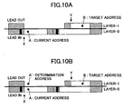
- one of the following two scanning paths (referred to as a scanning path A and a scanning path B, respectively) is employed, as a scanning path for scanning with an optical spot from an address (current address) on one recording layer (referred to as X) to an address (target address) on another recording layer (referred to as Y).
- a scanning path A focus jump is carried out in a current position X from the recording layer X to the recording layer Y.
- seeking is carried out for the target address.
- an address on the recording layer X at the same radial position as that of the target address with respect to the optical disk radial direction is set as a temporary target address.
- a single-side double-layer disk for example, a single-side double-layer DVD+R before finalization
- the entirety of a data zone of the layer 0 is an already-recorded zone, while, in the layer-1, a not-yet-recorded zone remains at a part (disk inner circumferential side) of the data zone, focus jump is carried out to the layer-1 in a position of an address 'a' as shown in FIG.
- information recorded at a target address may not be reproduced even when the target address is included in an already-recorded zone, for a case where a not-yet-recorded zone and the already-recorded zone are mixed in an optical disk.
- US2004/0076084A discloses a reproducing method for reproducing information from an optical disk having a plurality of recording layers including a first recording layer and a second recording layer, comprising the step of upon scanning with an optical spot from a first address on the first recording layer as a start point for a second address on the second recording layer which is a target address for reproducing in order to detect a reproduction position, selecting a scanning path for reaching the second address by scanning an already-recorded zone of at least one of the first recording layer and the second recording layer, from a first scanning path to carry out seeking after focus jump and a second scanning path to carry out seeking before focus jump, based on a positional relationship between a known boundary position between a not-yet-recorded zone and an already-recorded zone of the first recording layer or the second recording layer and the first address.
- the invention is in the method of claim 1, the apparatus of claim 5, the program of claim 9 and the medium of claim 13.
- the present invention can provide a reproducing method and an optical disk apparatus by which information recorded in an optical disk having a plurality of recording layers and having a not-yet-recorded zone and an already-recorded zone mixed therein can be properly and stably reproduced.
- the boundary position may be an end address of the user data of the partial zone recording the user data at the last from among the plurality of partial zones.
- the first scanning path may be a scanning path to seek for the second address in the second recording layer after a focus jump from the first recording layer to the second recording layer at the start point; and the second scanning path may be a scanning path to seek for the second address in the second recording layer after a focus jump from the first recording layer to the second recording layer at a third address after seeking is made from the start point in the first recording layer for the third address belonging to the first recording layer in the vicinity of the second address with respect to a radial direction of the optical disk.
- a direction from the third address for the second address may be the same as a direction in which an address increases in the second recording layer, with respect to the radial direction of the optical disk.
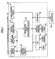
- FIG. 1 shows a general configuration of an optical disk apparatus 20 according to an embodiment of the present invention.
- the optical disk apparatus shown is an information processing apparatus, includes a spindle motor 22 for driving and rotating an optical disk 15 having a plurality of recording layers each having spiral or concentric tracks produced thereon, an optical pickup unit 23, a seek motor 21, a laser control circuit 24, a driving control circuit 26, a reproduced signal processing circuit 28, a buffer RAM 34, a buffer manager 37, an interface 38, a flash memory 39, a CPU 40 and a RAM 41, and reproduces information recorded in the optical disk 15.
- Arrows shown in FIG. 1 merely show flows of typical signals or information, and do not necessarily show all the connection relationship among the respective blocks.
- the optical disk apparatus 20 has a function to handle both the above-mentioned single-side double-layer DVD-ROM and the above-mentioned single-side double-layer DVD+R.
- the optical pickup unit 23 is a device for focusing laser light on any recording layer (referred to as a 'target recording layer'. hereinafter) of the plurality of recording layers of the optical disk 15, and also, receiving reflected light therefrom.
- the optical pickup unit 23 is configured to include a semiconductor laser, an objective lens for condensing a light flux emitted by the semiconductor laser on the target recording layer, a light receiving device receiving returning light reflected by the target recording layer and a driving system (a focusing actuator and a tracking actuator) driving the objective lens (each of which is not shown).
- the light receiving device includes a plurality of light receiving elements (or a plurality of light receiving zones), generates a signal (photoelectric signal) according to a light receiving amount for each light receiving device (or light receiving zone), and outputs these signals to the reproduced signal processing circuit 28.
- the focusing actuator is provided to drive the objective lens in an optical axis direction thereof.
- the tracking actuator is provided to drive the objective lens in a tracking direction perpendicular to any one of a track tangential direction and the optical axis direction of the objective lens.
- the seek motor 21 is provided to drive the optical pickup unit 23 in a sledge direction. Operation of driving the optical pickup unit 23 via the seek motor 21 to produce an optical spot in the vicinity of a target position is called coarse seeking operation, or simply, coarse seeking.
- the reproduced signal processing circuit 28 obtains a servo signal (a focus error signal, a tracking error signal and so forth) and an RF signal in the same manner as that of an optical disk apparatus in the prior art, based on the output signal of the light receiving devise (the plurality of photoelectric signals).
- the thus-obtained servo signal is output to the driving control circuit 26.
- the reproduced signal processing circuit 28 carries out decoding processing, error detecting processing and so forth on the RF signal. When error is found out there, error correction processing is carried out.
- the RF signal is stored in the buffer RAM 34 via the buffer manager 37 as reproduced data. Address information included in the reproduced data is output to the CPU 40.
- the driving control circuit 26 generates a driving signal for the tracking actuator based on the tracking error signal, for the reproduced signal processing circuit 28 for correcting positional error of the objective lens with respect to the tracking direction. Further, the driving control circuit 26 generates a driving signal for the focusing actuator based on the focus error signal from the reproduced signal processing circuit 28 for correcting a focus error of the objective lens. The thus-generated respective driving signals are output to the optical pickup unit 23. Thereby, tracking control and focus control are carried out. Operation of driving the tracking actuator to shift the objective lens and produce the optical spot at the target position is called fine seeking operation, or simply, fine seeking.
- the driving control circuit 26 generates a driving signal for driving the focusing actuator according to a so-called 'focus jump' instruction to change a position to produce the optical spot from one recording layer to another recording layer with respect to the optical axis direction of the objective lens.
- the thus-generated driving signal is output to the optical pickup unit 23.
- the driving control circuit 26 generates a driving signal for driving the seek motor 21 and a driving signal for driving the spindle motor 22 based on instructions from the CPU 40.
- the respective driving signals are output to the seek motor 21 and the spindle motor 22, respectively.
- buffer RAM 34 data (reproduced data) reproduced from the optical disk 15 is temporary stored. Input/output to/from the buffer RAM 34 is managed by the buffer manager 37.
- the laser control circuit 24 controls light emission power of the semiconductor laser included in the optical pickup unit 23. Specifically, a driving signal for the semiconductor laser is generated, and is output to the optical pickup unit 23.
- the interface 38 is a bi-directional interface between a host apparatus 90 (for example, a personal computer) and the optical disk apparatus 20, and conforms to standard interfaces such as ATAPI (AT attachment packet interface), SCSI (small computer system interface), USB (universal serial bus) and so forth.
- ATAPI AT attachment packet interface
- SCSI small computer system interface
- USB universal serial bus
- the flash memory 39 stores various types of programs including programs according to the present invention, described by code interpretable by the CPU 40, semiconductor laser light emitting characteristics, and so forth.
- the CPU 40 controls the respective parts mentioned above according to the programs store in the flash memory 39, and also, stores data necessary for the control in the RAM 41 and the buffer RAM 34.
- the DVD-ROM includes a single-layer DVD-ROM having a single recording layer and a single-side double-layer DVD-ROM mentioned above.
- the single-side double-layer disk includes those, with respect to a track path (reproducing scanning path), a parallel track path (refereed to as 'PTP', hereinafter) type and an opposite track path (referred to as 'OTP' hereinafter) type.
- an information area which is separated into a lead-in zone, a data zone and a lead-out zone is provided, from an inner circumferential side to an outer circumferential side of the optical disk, in a recording layer.
- a direction of a track path in this case is a direction from the lead-in zone for the lead-out zone.
- an information area separated into a lead-in zone, a data zone and a lead-out zone is provided in each recording layer from the disk inner circumferential side to the disk outer circumferential side, That is, in the DVD-ROM in the PTP type, the information area is provided separately for each recording layer, and each information area can be regarded as a separate recording layer from each other.
- a physical address increasing continuously from the lead-in zone for the lead-out zone is given.
- a direction of a track path in this case is a direction from the lead-in zone for the lead-out zone.
- a start position and an end poison of the lead-in zone, a start position of the data zone and an end potion of the lead-out zone are the same in their radial positions between the respective recording layers.
- start potions of the lead-out zones i.e., end positions of the data zones, may be different between the respective recording layers.
- lead out is recorded in a differential zone therebetween.
- the radial position means a position with respect to the disk's radial direction, measured from the disk's rotational center.
- a lead-in zone, a data zone and an intermediate zone are provided from the disk inner circumferential side to the disk outer circumferential side, while, in a layer-1, from the disk outer circumferential side for the disk inner circumferential side, an intermediate zone, a data zone and a lead-out zone are provided.
- a physical address continuously increasing from the lead-in zone for the intermediate zone is given, while, for the layer-1, a physical address inverted in bits from that of the physical address of the layer-0 is given from the intermediate zone for the lead-out zone.
- the layer-1 the physical address continuously increases from the intermediate zone for the lead-out zone.
- a direction of a track path in this case is a direction from the lead-in zone for the intermediate zone in the layer-0, while, is a direction from the intermediate zone for the lead-out zone in the layer-1. Accordingly, the layer-0 and the layer-1 can be regarded as a continuous single layer.
- a start position of the leads-in zone and an end position of the lead-out zone are the same in their radial positions; an end position of the data zone in the layer-0 and a start position of the data zone in the layer-1 are the same in their radial positions; and start positions and end positions of the intermediate zones are the same in their radial positions between the respective recording layers.
- a start position of the data zone in the layer-0 and an end position of the data zone in the layer-1 are not necessarily coincident in their radial positions.
- lead out is recorded in a differential zone therebetween, the same as the PTP-type single-side double-layer DVD-ROM.
- This optical disk 15 is a double-layer disk conforming to the standard of the above-mentioned single-side double-layer DVD+R.
- the single-side double-layer DVD+R is compatible with the above-mentioned OTP-type single-side double-layer DVD-ROM. It is noted that, hereinafter, a DVD+R having a single recording layer is referred to as a 'single-layer DVD+R'.
- the optical disk 15 is provided with a lead-in zone, a data zone and an intermediate zone in a layer-0 from the disk inner circumferential side to the disk outer circumferential side, while, in a layer-1, from the outer disk circumferential side to the disk inner circumferential side, an intermediate zone, a data zone and a lead-out zone are provided.
- a physical address continuously increasing from the lead-in zone for the intermediate zone is given, while, in the layer-1, a physical address inverted in bits from that of the layher-0 is given from the intermediate zone for the lead-out zone.
- the physical address increases from the intermediate zone for the lead-out zone, i.e., from the disk outer circumferential side to the disk inner circumferential side.
- the optical disk 15 is set in the optical disk apparatus 20 in such a manner that the recording layer nearer to the optical pickup unit 23 may be the layer-0.
- a direction of a track path corresponds to, the same as in the single-side double-layer DVD-ROM in the OTP type, a direction from the lead-in zone for the intermediate zone in the layer-0, while, a direction from the intermediate zone for the lead-out zone in the layer-1.
- the following two alternative types of scanning paths are applicable for scanning with an optical spot from a current address (first address) in one of the recording layers, i.e., the layer-0 and the layer-1 (first recording layer), as a start point, for a target address on the other recording layer (second recording layer).
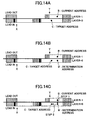
- a specific example of each scanning path is described below with reference to FIGS. 4A and 4B for a case of scanning with an optical spot from a current address on the layer-0 for a target address on the layer-1.
- Step 1 first the focusing actuator is driven, focus jump is carried out at a current address, and thus, a focus position of an optical spot with respect to the optical axis direction of the objective lens is changed from the layer-0 to the layer-1 (Step 1).
- Step 2 seeking is carried out on the layer-1 for the target address (Step 2).
- Step 2 the above-mentioned fine seeking is carried out when a seeking distance is so short that merely a shift by the tracking actuator may achieve it.
- the above-mentioned coarse seeing is carried out, and then, the fine seeking is caired out, when a seeking distance is so long that merely a shift by the tracking actuator may not achieve the seeking distance.
- Step 1 an address on the layer-0 in the vicinity of the radial position of the target address is set as a temporary target address (third address), and seeking is carried out for the temporary target address on the layer-0 (Step 1).
- Step 1 in order to shorten a seek time, only coarse seeing is carried out.
- Step 2 focus jump to the layer-1 is carried out (Step 2).
- Step 3 fine seeking is carried out for the target address on the layer-1 (Step 3).
- the single-side double-layer DVD+R the same as in a case of a single-layer DVD+R (see ECMA-349, for example), a multi-track, multi-session recording way is applied.
- the multi-session recording way of the optical disk 15 is briefly described below. It is noted that, recording of user data is carried out on the layer-0 in prior to that on the layer-1.
- a first session is made of lead in, user data and closure.
- Each of sessions starting from a second session is made of intro, user data and closure.
- a last session is made.of intro, user data and lead out.
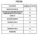
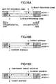
- Management information in the multi-session recording way includes, as shown in FIG. 5A , "identification ID', 'restriction information for unknown identification ID', 'drive ID', 'session number', a plurality of (in the example of FIG. 5A , N+1) 'session items', and 'reserved'.
- the identification ID stores an identification ID of the management information.
- the restriction information for unknown identification ID stores information concerning operation which a drive apparatus should restrict when the identification ID is unknown. As the restriction information, for example, information for inhibiting recording to the data zone, information for inhibiting rewriting of the management information, or such, may be applied.
- the session number stores a number of a session in which the management information is recorded.
- the session item stores information concerning sessions or fragments recorded in the disk, and includes a fragment item storing information concerning a fragment's recorded position in the disk and a previous session item storing information concerning a recorded position of a session preceding the relevant session.
- the reserved is a zone reserved for a future use.
- the fragment item includes, as shown in FIG. 5B , 'fragment item ID', 'fragment number', 'fragment start address', fragment end address', and 'reserved'.
- the fragment item ID stores the identification ID of the management information.
- the fragment number stores a number of a fragment managed by the management information.
- the fragment start address stores a start address of the fragment managed by the management information.
- the fragment end address stores an end address of the fragment managed by the management information.
- the reserved is a zone reserved for a future use.
- the previous session item is, as shown in FIG. 5C , information concerning the session preceding the relevant session, and includes 'previous session item ID', 'previous session number', 'previous session start address', previous session end address', and 'reserved'.
- the previous session item ID' stores the identification ID of the management information.
- the previous session number stores a number of a session managed by the management information.
- the previous session start address stores a start address of the session managed by the management information.
- the previous session end address stores an end address of the session managed by the management information.
- the reserved is a zone reserved for a future use.
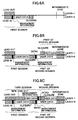
- FIG. 6A shows a state in which, user data is recorded in the first session, and then, the session is closed. Then, management information including information (start addresses and end addresses) concerning recorded positions of fragments included in the first session is recorded in a management information zone in the lead in. Further, predetermined information is recorded in the lead-out zone of the layer-1.
- a subsequent session (second session) is additionally recorded with the use of both recording layers, i.e., the layer-0 and the layer-1, and the session is closed.
- FIG. 6B shows this state.
- the user data is recorded with the use of both the recording layers.
- the intermediate zones of the respective recording layers data indicating that these zones are intermediate zones is recorded, respectively.
- management information including information (start addresses and end addresses) concerning recorded positions of fragments included in the second session and the information (the start address and the end address) concerning the recorded position of the first session are recorded in a management information zone in intro of the second session.
- a further subsequent session (third session) is additionally recorded, and then finalization is carried out.
- FIG. 6C shows this state.
- This third session is recorded in a zone subsequent to the second session, i.e., a zone on the inner circumferential side, and is a last session.
- management information including information (start addresses and end addresses) concerning recorded positions of fragments included in the third session, the information (the start address and the end address) concerning the recorded position of the second session and the information (the start address and the end address) concerning the recorded position of the first session are recorded in a management information zone in intro of the third session.
- new lead out is recorded, and thus, the entirety of the information area thus becomes an already-recorded zone in this optical disk.
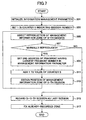
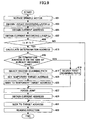
- a flow chart of FIG. 7 corresponds to a sequence of a processing algorithm carried out by the CPU 40. It is noted that, this boundary portion obtaining processing is carried out after, for example, ordinary predetermined initialization processing is finished, in the present embodiment.
- a start address of a program (referred to as a 'boundary position processing program', hereinafter) corresponding to the flow chart of FIG. 7 stored in the flash memory 39 is set in the program counter of the CPU 40, and the boundary position obtaining processing starts.
- Step 301 a management information parameter, held by the RAM 41 for identifying a boundary position, is initialized. Specifically, for example, 'FFFFFFh' is set there.
- Step 303 1 is set in a counter S indicating a session number.
- Step 307 it is determined whether or not reproduction of the management information zone has been finished properly. In this case since the management information is positively recorded in the management information zone of the lead in, the determination result is Yes, and Step 309 is then executed.
- Step 309 an end address of a fragment having the largest fragment number in the management information thus reproduced is set in the management information parameter.
- an end address of a zone in which user data of a first session is recorded is set in the management information parameter.
- Step 313 a position of a management information zone of a S-th session (in this case, a second session) is calculated.
- a position of a management information zone of a S-th session (in this case, a second session) is calculated.
- sizes of closure and intro are the same throughout all the sessions, and also, a position of the management information zone in the intro is fixed. Accordingly, the position of the management information zone of the S-th session can be calculated based on the management information parameter.
- Step 305 is returned to.
- Step 305 a management information zone of intro of the second session is reproduced.
- Step 309 as shown in FIG. 8B for example, an end address of a zone in which user data is recorded in the second session is set in the management information parameter. That is, the management information parameter is thus updated.
- Step 313 a position of a management information zone in a S-th session (in this case, a third session) is calculated. Then, Step 305 is returned to.
- Step 305 a management information zone in intro of the S-th session (third session) is reproduced.
- Step 315 is executed in this case.
- Step 315 the (S-1)-th session (in this case, the second session) is determined as a last session.
- Step 317 it is determined that a zone starting from a top address (referred to as X) of the data zone in the layer-0 up to an address (referred to as Y) stored in the management information parameter, is an already-recorded zone.
- a zone in which closure is recorded referred to as a 'closure zone', hereinafter
- a not-yet-recorded zone is regarded as a not-yet-recorded zone.
- information (the address X and the address Y) concerning the thus-determined already-recorded zone is stored in the RAM 41 as the already-recorded zone information. Then, the boundary position obtaining processing is finished. That is, a boundary between the already-recorded zone (in this example, the above-mentioned already-recorded zone between the address X and the address y) and the not-yet-recorded zone (in this case a zone between the address Y and the start address of the lead out, in FIG. 8D ) is thus obtained.
- the already-recorded zone in this example, the above-mentioned already-recorded zone between the address X and the address y
- the not-yet-recorded zone in this case a zone between the address Y and the start address of the lead out, in FIG. 8D
- FIG. 9 A flow chart of FIG. 9 corresponds to a sequence of a processing program executed by the CPU 40.
- a start address of a program (refereed to as a 'reproduction processing program', hereinafter) corresponding to the flow chart of FIG. 9 is set in the program counter of the CPU 40.
- reproduction processing starts.
- Step 401 a control signal for controlling a rotation of the spindle motor 22 is generated based on a reproduction speed, is output to the driving control circuit 26, and also, a matter that the reproduction request command has been received from the host apparatus 90 is notified of to the reproduced signal processing circuit 28.
- the above-mentioned tracking control and focus control are carried out.
- the tracking control and focus control are carried out as is necessary until the reproduction processing is finished.
- Step 403 an address attached to the reproduction request command (referred to as a target address) is extracted therefrom, and a recording layer (referred to as a target recording layer Lt) to which the target address belongs is obtained.
- a target address an address attached to the reproduction request command
- Lt a recording layer
- Step 405 based on address information from the reproduced signal processing circuit 28, an address (referred to as a current address) of a zone on which an optical spot is currently produced is obtained.
- Step 407 a recording layer (referred to as a current recording layer Ln, hereinafter) to which the current address belongs is obtained.
- Step 409 it is determined whether or not the target address Lt and the current address Ln are different from one another. When both addressees Lt and Ln are different from one another, the determination result becomes Yes, and Step 413 is executed then.
- Step 413 an address belonging to the target recording layer Lt in the vicinity of a radial position of the current address is calculated, and the thus-obtained address is referred to as a determination address.
- Step 415 the above-mentioned already-recorded recording zone information stored in the RAM 41 is referred to, and it is determined whether to not the above-mentioned determination address is included in the already-recorded zone.
- the determination address in this case, an address A'
- Step 417 is executed then.
- Step 417 the second scanning path is selected from the above-mentioned first and second scanning paths.
- Step 423 an address in the vicinity of a position having the same radial position as that of the target address in the current recording layer Ln is set as a temporary target address.
- a temporary target address in this case, an address B'
- an address at a position on the layer-0 shifted on the outer circumferential side by approximately 0.1 mm from the radial position of the target address is set as the temporary target address. This is in order that, a direction from the temporary target address for the target address with respect to the optical disk radial direction may coincide with a direction of an address increasing in the layer-1.
- an optical disk having a plurality of recording layers is manufactured as a result of the recording layers produced separately being stuck to each other.
- Relative positional relationship among the respective recording layers may deviate from a designed one when they are stuck to each other. Even when this deviation may fall within an allowable range, a recording layer in which an actual radial position does not coincide with a designed radial position obtained from an address may occur. Accordingly, if the same radial position as that of the target address is set as that of the temporary target address, an address of an optical spot after focus jump may not coincide with the target address.
- the not-yet-recorded zone may be accessed as a result of the focus jump.
- the direction from the temporary target address for the target address with respect to the optical disk radial direction is made to coincide with the direction of the address increasing as mentioned above.
- the temporary target address is set on the outer circumferential side of the target address in the optical disk radial direction.
- the temporary target address is set on the inner circumferential side of the target address in the optical disk radial direction.
- Step 425 a direction for coarse seeking for the above-mentioned temporary target address is given to the driving control circuit 26.
- Step 427 when it is confirmed that coarse seeking to the temporary target address has been carried out, based on address information from the reproduced signal processing circuit 28, the driving control circuit 26 is directed to carry out focus jump to the layer-1.
- Step 429 based on address information from the reproduced signal processing circuit 28, an address of a zone in which an optical spot is currently produced is obtained.
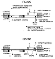
- Step S431 the driving control circuit 26 is directed to carry out fine seeking to the target address. That is, when the target recording layer Lt and the current recording layer Ln are different from one another, and the determination address is included in the not-yet-recorded zone, the second scanning path is selected. As a result, the target address is reached by the following three steps, i.e., (1) coarse seeking to the temporary target address, (2) focus jump and then (3) fine seeking to the target address, as shown in FIG. 10D for example.
- Step 433 when it is confirmed from address information from the reproduced signal processing circuit 28 that seeking to the target address has been achieved, the reproduced signal processing circuit 28 is directed to carry out actual data reading. As a result, the reproduced signal processing circuit 28 obtains reproduced data, which is then stored in the buffer RAM 34. The reproduced data is then transferred to the host apparatus 90 in sector units via the buffer manager 37 and the interface 38. When data reproduction is thus completed for data designated by the host apparatus 90, predetermined finish processing is carried out, and the reproduction processing is finished.
- Step 415 the determination address (in this case, an address C') is included in the not-yet-recorded zone as shown in FIG. 11B . Therefore, the determination result in Step 415 is Yes, and Step 419 is carried out then.
- Step 419 the first scanning path is selected from the first and second scanning paths. Then, Step S427 is carried out.
- Step 429 focus jump to the layer-1 is carried out at the current address.
- the driving control circuit 26 is directed to carry out seeking from the focus jump position to the target position.
- fine seeking is carried out.
- coarse seeking is carried out first and after that, fine seeking is carried out.
- the above-mentioned first scanning path is selected.
- the target address is reached through two steps, i.e., (1) focus jump and then (2) seeking to the target address.
- Step 431 is carried out then.
- fine seeking is carried out when a seeking distance is so long that only a shift of the objective lens by the tracking actuator may not achieve the distance.
- coarse seeking is carried first out and after that, fine seeking is carried out.
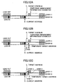
- the same processing as the above-mentioned reproduction processing may be carried out, for reproducing the management information zone in intro of the third session in the management information parameter obtaining processing before the information concerning the boundary position between the not-yet-recorded zone and the already-recorded zone is obtained.
- an end address of the user data in the second session can be regarded as a temporary management information parameter
- the management information zone in intro of the second session is regarded as a current address (address D)
- the management information zone in intro of the third session is regarded as a target address (address E).
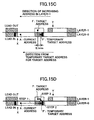
- a temporary target address (address E') is set, and, as shown in FIG. 12C , the target address is reached in the second scanning path (through Step 1 through Step 3s, shown).
- the determination address is an address included in the already-recorded zone as shown in FIG. 13B , and the target address is reached in the first scanning path as shown in FIG. 13C (through Step 1 and Step 2 shown).
- the determination address is an address included in the already-recorded zone as shown in FIG. 14B , and the target address is reached in the first scanning path as shown in FIG. 14C (through Step 1 and Step 2 shown).
- a control unit is realized from the CPU 40 and the program executed by the CPU 40 in the optical disk apparatus 20 in the present embodiment. That is, the control unit is realized by Steps 403 through 431 of FIG. 9 . It is noted that, at least a part of the control unit thus realized by processing carried out by the CPU 40 according to the program may be configured by hardware. Or, all thereof may be configured by hardware. Further, a processing unit is configured by the reproduced signal processing circuit 28.
- a program according to the present invention is configured by the above-mentioned reproduction processing program of the programs stored by the flash memory 39 as a computer readable information recording medium. That is, a selecting step is configured by a program corresponding to Steps 403 though 419 of FIG. 9 .
- a reproducing method according to the present invention is executed. That is, a selecting step is executed by processing of Steps 403 through 419 of FIG. 9 .
- the optical disk apparatus when the optical disk 15 having the two recording layers and having, in its information area, the not-yet-recorded zone and the already-recorded zone mixed therein is set, the management information parameter indicating the boundary position between the not-yet-recorded zone and the already-recorded zone is obtained. Then, when receiving a reproduction request command from the host apparatus 90, the reproduction request command is responded to, and an optical spot is applied to scan from a current address (first address) as a start point on a current recording layer Ln (first recording layer) for a reproduction target address (second address) on a target recording layer Lt (second recording layer).
- a determination address obtained from the current address and a management information parameter are referred to, and the second scanning path is selected when the determination address is included in the not-yet-recorded zone, while, the first scanning path is selected when the determination address is included in the already-recorded zone.
- the optical spot is applied to scan for the target address along the already-recorded zone of the layer-0 and the layer-1, and thus, address information required for the scanning can be appropriately and properly obtained during the scanning.
- the optical spot can be precisely produced at the target address finally. Accordingly, information recorded in the optical disk having the plurality of recording layers and having the not-yet-recorded zone and the already-recorded zone mixed therein can be properly and stably reproduced.
- an address on the layer-0 at a position shifted from a radial position of a target address by approximately 0.1 mm to the outer circumferential side is set as a temporary target address.
- management information recorded in a management information zone in lead in (or intro) is obtained from a first session in sequence, for searching for a last session.
- a way of searching for a last session is not limited thereto.
- the management information parameter may be obtained based on that information.
- the management information parameter may be obtained based on that information.
- the management information parameter is obtained by the above-mentioned boundary position obtaining processing.
- the management information parameter thus obtained as the same as the management information parameter obtained in the above-mentioned embodiment.
- the determination address in this case, an address A'
- FIGS. 15C and 15D the second scanning path is selected.
- the address on the layer-0 shifted from the radial position of the target address to the outer circumferential side is set as the temporary target address.
- the temporary address should not be positively shifted when a possibility that focus jump results in access to the not-yet-recorded zone is almost zero.
- the optical disk confirms to the single-side double-layer DVD+R standard.
- the present invention is not limited thereto.
- a single-side double-layer optical disk in a next generation prepared for light of approximately 405 nm may also be applied instead.
- the optical disk has the two recording layers.
- the present invention is not limited thereto.
- an optical disk having more than two recording layers may also be applied instead.
- the programs according to the present invention are stored in the flash memory 39.
- the same may be stored in another type of a computer readable information recording medium (a CD, a magnetooptical disk, a DVD, a memory card, a flexible disk, or such).
- the programs according to the present invention are loaded in the flash memory 39 with the use of a reproducing device (or a special interface) prepared for handling each of these information recording media.
- the programs according to the present invention may be transferred to the flash memory 39 via a communication network (a LAN, an intranet, the Internet. or such). In any way, the programs according to the present invention should be loaded in the flash memory 39.
- the optical disk apparatus may be provided with a plurality of semiconductor lasers emitting light fluxes (or laser beams) having different wavelengths, respectively.
- the optical disk apparatus may be one which can handle, by itself alone, a plurality of types of optical disks conforming to a plurality of different standards, respectively. In this layers.
- a reproducing method according to the present invention is advantageous for properly and stably reproducing information recorded in an optical disk having a plurality of recording layers and having a not-yet-recorded zone and an already-recorded zone mixed therein.
- an optical disk apparatus according to the present invention is advantageous for properly and stably reproducing information recorded in an optical disk having a plurality of recording layers and having a not-yet-recorded zone and an already-recorded zone mixed therein.
- a program and a computer readable information recording medium storing the program according to the present invention is advantageous for causing an optical disk apparatus to properly and stably reproducing information recorded in an optical disk having a plurality of recording layers and having a not-yet-recorded zone and an already-recorded zone mixed therein.
Landscapes
- Optical Recording Or Reproduction (AREA)
- Moving Of The Head For Recording And Reproducing By Optical Means (AREA)
Claims (13)
- Procédé de reproduction pour reproduire des informations d'un disque optique ayant une pluralité de couches d'enregistrement comprenant une première couche d'enregistrement et une seconde couche d'enregistrement, comprenant l'étape suivante :lors du balayage avec un point optique provenant d'une première adresse sur la première couche d'enregistrement tenant lieu de point de départ pour une deuxième adresse sur la seconde couche d'enregistrement qui est une adresse cible de reproduction de manière à détecter une position de reproduction, sélectionner un trajet de balayage pour atteindre la deuxième adresse en balayant une zone déjà enregistrée d'au moins une couche parmi la première couche d'enregistrement et la seconde couche d'enregistrement, à partir d'un premier trajet de balayage pour mener une recherche après un saut de focalisation et un second trajet de balayage pour mener une recherche grossière avant un saut de focalisation et une recherche précise après le saut de focalisation, sur la base d'une relation de positionnement entre une position limite connue entre une zone qui n'est pas encore enregistrée et une zone déjà enregistrée de la première couche d'enregistrement ou de la seconde couche d'enregistrement et de la première adresse,où le premier trajet de balayage est sélectionné lorsqu'une adresse de détermination appartenant à la seconde couche d'enregistrement au voisinage de la première adresse est incluse dans ladite zone déjà enregistrée relativement à la direction radiale du disque optique, et le second trajet de balayage est sélectionné lorsqu'une adresse de détermination appartenant à la seconde couche d'enregistrement au voisinage de la première adresse est incluse dans ladite zone qui n'est pas encore enregistrée relativement à la direction radiale du disque optique.
- Procédé de reproduction tel que revendiqué dans la revendication 1, dans lequel :ladite zone déjà enregistrée comprend une pluralité de zones partielles enregistrant des données d'utilisateur séparément ; etladite position limite comprend une adresse de fin des données d'utilisateur de la zone partielle enregistrant les données d'utilisateur dans la dernière parmi la pluralité de zones partielles.
- Procédé de reproduction tel que revendiqué dans la revendication 1, dans lequel :le premier trajet de balayage comprend un trajet de balayage pour mener une recherche de la deuxième adresse dans la seconde couche d'enregistrement après un saut de focalisation de la première couche d'enregistrement vers la seconde couche d'enregistrement au niveau dudit point de départ ; etledit second trajet de balayage comprend un trajet de balayage pour mener une recherche précise de la deuxième adresse dans la seconde couche d'enregistrement après un saut de focalisation de la première couche d'enregistrement vers la seconde couche d'enregistrement au niveau d'une troisième adresse après qu'une recherche grossière a été effectuée à partir dudit point de départ dans la première couche d'enregistrement pour la troisième adresse appartenant à la première couche d'enregistrement dans le voisinage de la deuxième adresse relativement à une direction radiale du disque optique.
- Procédé de reproduction tel que revendiqué dans la revendication 3, dans lequel :dans ledit second trajet de balayage, une direction depuis la troisième adresse pour la deuxième adresse est la même qu'une direction dans laquelle une adresse augmente dans la seconde couche d'enregistrement, relativement à la direction radiale du disque optique.
- Appareil de disque optique (20) destiné à reproduire des informations provenant d'un disque optique (15) comprenant une pluralité de couches d'enregistrement comprenant une première couche d'enregistrement et une seconde couche d'enregistrement, comprenant :une unité de lecture optique (23) configurée pour produire un point optique sur l'une quelconque de la pluralité de couches d'enregistrement du disque optique via l'utilisation d'une lentille de focalisation, et pour recevoir la lumière réfléchie par ladite couche d'enregistrement ;une unité de contrôle configurée pour, lors du balayage avec un point optique provenant d'une première adresse sur la première couche d'enregistrement tenant lieu de point de départ pour une deuxième adresse sur la seconde couche d'enregistrement, qui est une adresse cible de reproduction, de manière à détecter une position de reproduction, sélectionner un trajet de balayage pour atteindre la deuxième adresse en balayant une zone déjà enregistrée d'au moins une couche parmi la première couche d'enregistrement et la seconde couche d'enregistrement, à partir d'un premier trajet de balayage pour mener une recherche après un saut de focalisation et un second trajet de balayage pour mener une recherche grossière avant un saut de focalisation et une recherche précise après le saut de focalisation, sur la base d'une relation de positionnement entre une position limite connue entre une zone qui n'est pas encore enregistrée et une zone déjà enregistrée de la première couche d'enregistrement ou de la seconde couche d'enregistrement et de la première adresse ; et contrôler l'unité de lecture optique pour effectuer un balayage avec le point optique le long dudit trajet de balayage ; etune unité de traitement configurée pour reproduire des informations via l'utilisation d'un signal de sortie de ladite unité de lecture optique,où ladite unité de contrôle est configurée pour sélectionner le premier trajet de balayage lorsqu'une adresse de détermination appartenant à la seconde couche d'enregistrement au voisinage de la première adresse est incluse dans ladite zone déjà enregistrée relativement à la direction radiale du disque optique, et pour sélectionner le second trajet de balayage lorsqu'une adresse de détermination appartenant à la seconde couche d'enregistrement au voisinage de la première adresse est incluse dans ladite zone qui n'est pas encore enregistrée relativement à la direction radiale du disque optique.
- Appareil de disque optique tel que revendiqué dans la revendication 5, dans lequel :ladite zone déjà enregistrée comprend une pluralité de zones partielles enregistrant des données d'utilisateur séparément ; etladite position limite comprend une adresse de fin des données d'utilisateur de la zone partielle enregistrant les données d'utilisateur dans la dernière parmi la pluralité de zones partielles.
- Appareil de disque optique tel que revendiqué dans la revendication 5, dans lequel :le premier trajet de balayage comprend un trajet de balayage pour mener une recherche de la deuxième adresse dans la seconde couche d'enregistrement après un saut de focalisation de la première couche d'enregistrement vers la seconde couche d'enregistrement au niveau dudit point de départ ; etledit second trajet de balayage comprend un trajet de balayage pour mener une recherche précise de la deuxième adresse dans la seconde couche d'enregistrement après un saut de focalisation de la première couche d'enregistrement vers la seconde couche d'enregistrement au niveau d'une troisième adresse après qu'une recherche grossière ait été effectuée à partir dudit point de départ dans la première couche d'enregistrement pour la troisième adresse appartenant à la première couche d'enregistrement dans le voisinage de la deuxième adresse relativement à une direction radiale du disque optique.
- Appareil de disque optique tel que revendiqué dans la revendication 7, dans lequel :dans ledit second trajet de balayage, une direction depuis la troisième adresse pour la deuxième adresse est la même qu'une direction dans laquelle une adresse augmente dans la seconde couche d'enregistrement, relativement à la direction radiale du disque optique.
- Programme appliqué dans un appareil de disque optique pour reproduire des informations d'un disque optique ayant une pluralité de couches d'enregistrement comprenant une première couche d'enregistrement et une seconde couche d'enregistrement, comprenant des instructions pour amener un ordinateur, pourvu pour contrôler l'appareil de disque optique, à exécuter l'étape suivante :lors du balayage avec un point optique provenant d'une première adresse sur la première couche d'enregistrement tenant lieu de point de départ pour une deuxième adresse sur la seconde couche d'enregistrement qui est une adresse cible de reproduction de manière à détecter une position de reproduction, sélectionner un trajet de balayage pour atteindre la deuxième adresse en balayant une zone déjà enregistrée d'au moins une couche parmi la première couche d'enregistrement et la seconde couche d'enregistrement, à partir d'un premier trajet de balayage pour mener une recherche après un saut de focalisation et un second trajet de balayage pour mener une recherche grossière avant un saut de focalisation et une recherche précise après le saut de focalisation, sur la base d'une relation de positionnement entre une position limite connue entre une zone qui n'est pas encore enregistrée et une zone déjà enregistrée de la première couche d'enregistrement ou de la seconde couche d'enregistrement et de la première adresse,où le premier trajet de balayage est sélectionné lorsqu'une adresse de détermination appartenant à la seconde couche d'enregistrement au voisinage de la première adresse est incluse dans ladite zone déjà enregistrée relativement à la direction radiale du disque optique, et le second trajet de balayage est sélectionné lorsqu'une adresse de détermination appartenant à la seconde couche d'enregistrement au voisinage de la première adresse est incluse dans ladite zone qui n'est pas encore enregistrée relativement à la direction radiale du disque optique.
- Programme tel que revendiqué dans la revendication 9, dans lequel :ladite zone déjà enregistrée comprend une pluralité de zones partielles enregistrant des données d'utilisateur séparément ; etladite position limite comprend une adresse de fin des données d'utilisateur de la zone partielle enregistrant les données d'utilisateur dans la dernière parmi la pluralité de zones partielles.
- Programme tel que revendiqué dans la revendication 9, dans lequel :le premier trajet de balayage comprend un trajet de balayage pour mener une recherche de la deuxième adresse dans la seconde couche d'enregistrement après un saut de focalisation de la première couche d'enregistrement vers la seconde couche d'enregistrement au niveau dudit point de départ ; etledit second trajet de balayage comprend un trajet de balayage pour mener une recherche précise de la deuxième adresse dans la seconde couche d'enregistrement après un saut de focalisation de la première couche d'enregistrement vers la seconde couche d'enregistrement au niveau d'une troisième adresse après qu'une recherche grossière ait été effectuée à partir dudit point de départ dans la première couche d'enregistrement pour la troisième adresse appartenant à la première couche d'enregistrement dans le voisinage de la deuxième adresse relativement à une direction radiale du disque optique.
- Programme tel que revendiqué dans la revendication 11, dans lequel :dans ledit second trajet de balayage, une direction depuis la troisième adresse pour la deuxième adresse est la même qu'une direction dans laquelle une adresse augmente dans la seconde couche d'enregistrement, relativement à la direction radiale du disque optique.
- Support d'enregistrement d'informations lisibles par un ordinateur sur lequel est stocké le programme revendiqué dans les revendications 9, 10, 11 ou 12.
Applications Claiming Priority (2)
| Application Number | Priority Date | Filing Date | Title |
|---|---|---|---|
| JP2004302562A JP2006114168A (ja) | 2004-10-18 | 2004-10-18 | 再生方法、光ディスク装置、プログラム及び記録媒体 |
| PCT/JP2005/019353 WO2006043649A1 (fr) | 2004-10-18 | 2005-10-14 | Procede de reproduction, appareil de disque optique, programme et support d'enregistrement a informations lisibles par un ordinateur |
Publications (3)
| Publication Number | Publication Date |
|---|---|
| EP1803120A1 EP1803120A1 (fr) | 2007-07-04 |
| EP1803120A4 EP1803120A4 (fr) | 2012-11-28 |
| EP1803120B1 true EP1803120B1 (fr) | 2014-05-07 |
Family
ID=35432466
Family Applications (1)
| Application Number | Title | Priority Date | Filing Date |
|---|---|---|---|
| EP05795314.3A Expired - Lifetime EP1803120B1 (fr) | 2004-10-18 | 2005-10-14 | Procede de reproduction, appareil de disque optique, programme et support d'enregistrement a informations lisibles par un ordinateur pour effectuer un saut de couche sur un disque optique multicouche |
Country Status (5)
| Country | Link |
|---|---|
| US (1) | US7995438B2 (fr) |
| EP (1) | EP1803120B1 (fr) |
| JP (1) | JP2006114168A (fr) |
| CN (1) | CN101044560B (fr) |
| WO (1) | WO2006043649A1 (fr) |
Families Citing this family (5)
| Publication number | Priority date | Publication date | Assignee | Title |
|---|---|---|---|---|
| JP4666234B2 (ja) | 2008-04-17 | 2011-04-06 | ソニー株式会社 | 光ディスク装置および光ディスク再生方法 |
| JP4596284B2 (ja) | 2008-05-26 | 2010-12-08 | ソニー株式会社 | 光ディスク装置及びフォーカス制御方法 |
| JP4662186B2 (ja) | 2008-05-30 | 2011-03-30 | ソニー株式会社 | 光ディスク装置及び補正サーボ制御信号生成方法 |
| JP2013131810A (ja) * | 2011-12-20 | 2013-07-04 | Fujitsu Ltd | 通信装置、通信システム、コンピュータプログラム及びセッション制御方法 |
| JP7480502B2 (ja) * | 2019-12-20 | 2024-05-10 | 株式会社Jvcケンウッド | 記録装置、記録方法及びプログラム |
Family Cites Families (22)
| Publication number | Priority date | Publication date | Assignee | Title |
|---|---|---|---|---|
| US5272194A (en) | 1992-01-17 | 1993-12-21 | E. I. Du Pont De Nemours And Company | Process for preparing a strengthened polyimide film containing organometallic compounds for improving adhesion |
| US5543222A (en) | 1994-04-29 | 1996-08-06 | E. I. Du Pont De Nemours And Company | Metallized polyimide film containing a hydrocarbyl tin compound |
| JPH09282675A (ja) | 1996-04-15 | 1997-10-31 | Nec Corp | 多層光ディスク装置 |
| JP2000251271A (ja) * | 1999-02-25 | 2000-09-14 | Sony Corp | ディスクドライブ装置 |
| KR20010113646A (ko) | 1999-11-12 | 2001-12-28 | 요트.게.아. 롤페즈 | 데이터-보유 디스크들로부터 정보를 재생하는 장치 |
| JP3860394B2 (ja) * | 2000-06-20 | 2006-12-20 | 株式会社リコー | 情報再生方法及び情報再生装置 |
| JP2002008252A (ja) | 2000-06-22 | 2002-01-11 | Toshiba Corp | 光ディスク装置及び光ディスクアクセス制御方法 |
| JP4006184B2 (ja) * | 2001-01-30 | 2007-11-14 | 株式会社リコー | 情報記録再生方法、情報記録再生装置、情報処理装置及びコンピュータ・プログラム |
| JP2002324363A (ja) * | 2001-04-25 | 2002-11-08 | Ricoh Co Ltd | 情報記録再生装置 |
| TW514893B (en) * | 2001-06-18 | 2002-12-21 | Acer Labs Inc | Long seeking control system for disc drive and method thereof |
| JP3878442B2 (ja) * | 2001-07-30 | 2007-02-07 | 株式会社リコー | 情報記録再生装置とプログラム |
| JP3886800B2 (ja) * | 2001-12-19 | 2007-02-28 | 株式会社リコー | データ管理情報取得方法、情報再生装置、並びにデータ管理情報取得プログラム及び記録媒体 |
| JP4100913B2 (ja) * | 2002-01-15 | 2008-06-11 | 株式会社リコー | 情報再生装置、データ管理情報取得方法、データ管理情報取得プログラム、記憶媒体、及び再生システム |
| JP2004005842A (ja) * | 2002-05-31 | 2004-01-08 | Ricoh Co Ltd | 記録方法、記録媒体、プログラム及び情報記録媒体、並びに情報記録装置 |
| JP3772136B2 (ja) * | 2002-07-30 | 2006-05-10 | 株式会社東芝 | 光ディスク装置と光ディスク装置のアクセス方法 |
| JP4183553B2 (ja) * | 2002-09-19 | 2008-11-19 | 株式会社リコー | 記録方法、プログラム及び記録媒体、並びに情報記録装置 |
| JP3867038B2 (ja) * | 2002-10-23 | 2007-01-10 | 株式会社リコー | 情報記録装置と情報記録方法とプログラムと記録媒体 |
| JP3710790B2 (ja) * | 2003-03-24 | 2005-10-26 | 株式会社リコー | 情報記録方法及びその装置 |
| KR100564618B1 (ko) * | 2004-03-11 | 2006-03-28 | 삼성전자주식회사 | 디스크 드라이브의 층간 탐색 방법 |
| JP4713839B2 (ja) * | 2004-03-17 | 2011-06-29 | 株式会社日立エルジーデータストレージ | 光ディスク装置及びそのフォーカスジャンプ制御方法 |
| JP2005327425A (ja) * | 2004-05-17 | 2005-11-24 | Matsushita Electric Ind Co Ltd | 光ディスク装置におけるフォーカス制御方法 |
| TWI253067B (en) * | 2004-06-15 | 2006-04-11 | Lite On It Corp | Intelligent layer jump method |
-
2004
- 2004-10-18 JP JP2004302562A patent/JP2006114168A/ja active Pending
-
2005
- 2005-10-14 WO PCT/JP2005/019353 patent/WO2006043649A1/fr not_active Ceased
- 2005-10-14 CN CN2005800356068A patent/CN101044560B/zh not_active Expired - Fee Related
- 2005-10-14 US US11/665,372 patent/US7995438B2/en not_active Expired - Fee Related
- 2005-10-14 EP EP05795314.3A patent/EP1803120B1/fr not_active Expired - Lifetime
Also Published As
| Publication number | Publication date |
|---|---|
| US7995438B2 (en) | 2011-08-09 |
| EP1803120A1 (fr) | 2007-07-04 |
| JP2006114168A (ja) | 2006-04-27 |
| CN101044560B (zh) | 2011-05-11 |
| WO2006043649A1 (fr) | 2006-04-27 |
| EP1803120A4 (fr) | 2012-11-28 |
| CN101044560A (zh) | 2007-09-26 |
| US20070288949A1 (en) | 2007-12-13 |
Similar Documents
| Publication | Publication Date | Title |
|---|---|---|
| CN1574053B (zh) | 记录介质、记录装置和记录方法 | |
| US7385897B2 (en) | Information recording device, information recording method, information recording program, and recording medium | |
| US7573799B2 (en) | Information recording method, information recording apparatus, program and computer readable information storage medium | |
| CN1879161B (zh) | 信息方法和信息记录装置 | |
| JP2004326917A (ja) | 再生方法、プログラム及び記録媒体、並びにドライブ装置 | |
| US7539114B2 (en) | Recording apparatus and recording method | |
| EP1803120B1 (fr) | Procede de reproduction, appareil de disque optique, programme et support d'enregistrement a informations lisibles par un ordinateur pour effectuer un saut de couche sur un disque optique multicouche | |
| EP1834323B1 (fr) | Realisation d'une operation d'acces exempte d'erreur sur disque multicouches | |
| US7719945B2 (en) | Information recording method allowing improved access to a recording start position of user data in an information recording medium and apparatus performing the same | |
| EP1880380B1 (fr) | Procede d'enregistrement de disque optique, disque optique et support d'information | |
| JP2011048884A (ja) | 光ディスク、光ディスク再生装置、再生方法及び光ディスク装置 | |
| US7843779B2 (en) | Recording method, information recording medium, reproducing method, information recording device, and information reproducing device | |
| JP4315253B2 (ja) | 情報記録媒体 | |
| JP2006313600A (ja) | 記録方法、プログラム及び記録媒体、並びに情報記録装置 | |
| KR20100017674A (ko) | 광 드라이브의 디스크 기동 시간 | |
| JPWO2006107033A1 (ja) | 情報記録装置及び方法、記録制御用のコンピュータプログラム、並びに情報記録媒体 | |
| JP2004265475A (ja) | 光ディスク装置とそのフォーカス制御方法 | |
| JP2006294174A (ja) | 光ディスク装置 |
Legal Events
| Date | Code | Title | Description |
|---|---|---|---|
| PUAI | Public reference made under article 153(3) epc to a published international application that has entered the european phase |
Free format text: ORIGINAL CODE: 0009012 |
|
| 17P | Request for examination filed |
Effective date: 20070418 |
|
| AK | Designated contracting states |
Kind code of ref document: A1 Designated state(s): DE ES FR GB IT NL |
|
| DAX | Request for extension of the european patent (deleted) | ||
| RBV | Designated contracting states (corrected) |
Designated state(s): DE ES FR GB IT NL |
|
| RIC1 | Information provided on ipc code assigned before grant |
Ipc: G11B 7/085 20060101ALI20091111BHEP Ipc: G11B 27/10 20060101AFI20091111BHEP |
|
| RIC1 | Information provided on ipc code assigned before grant |
Ipc: G11B 27/10 20060101AFI20120411BHEP Ipc: G11B 7/085 20060101ALI20120411BHEP |
|
| A4 | Supplementary search report drawn up and despatched |
Effective date: 20121029 |
|
| REG | Reference to a national code |
Ref country code: DE Ref legal event code: R079 Ref document number: 602005043591 Country of ref document: DE Free format text: PREVIOUS MAIN CLASS: G11B0007085000 Ipc: G11B0027100000 |
|
| GRAP | Despatch of communication of intention to grant a patent |
Free format text: ORIGINAL CODE: EPIDOSNIGR1 |
|
| INTG | Intention to grant announced |
Effective date: 20131220 |
|
| RIC1 | Information provided on ipc code assigned before grant |
Ipc: G11B 7/00 20060101ALN20131206BHEP Ipc: G11B 7/085 20060101ALI20131206BHEP Ipc: G11B 27/10 20060101AFI20131206BHEP |
|
| GRAS | Grant fee paid |
Free format text: ORIGINAL CODE: EPIDOSNIGR3 |
|
| GRAA | (expected) grant |
Free format text: ORIGINAL CODE: 0009210 |
|
| AK | Designated contracting states |
Kind code of ref document: B1 Designated state(s): DE ES FR GB IT NL |
|
| REG | Reference to a national code |
Ref country code: GB Ref legal event code: FG4D |
|
| REG | Reference to a national code |
Ref country code: DE Ref legal event code: R096 Ref document number: 602005043591 Country of ref document: DE Effective date: 20140618 |
|
| REG | Reference to a national code |
Ref country code: NL Ref legal event code: T3 |
|
| PG25 | Lapsed in a contracting state [announced via postgrant information from national office to epo] |
Ref country code: ES Free format text: LAPSE BECAUSE OF FAILURE TO SUBMIT A TRANSLATION OF THE DESCRIPTION OR TO PAY THE FEE WITHIN THE PRESCRIBED TIME-LIMIT Effective date: 20140507 |
|
| REG | Reference to a national code |
Ref country code: DE Ref legal event code: R097 Ref document number: 602005043591 Country of ref document: DE |
|
| PLBE | No opposition filed within time limit |
Free format text: ORIGINAL CODE: 0009261 |
|
| STAA | Information on the status of an ep patent application or granted ep patent |
Free format text: STATUS: NO OPPOSITION FILED WITHIN TIME LIMIT |
|
| 26N | No opposition filed |
Effective date: 20150210 |
|
| PG25 | Lapsed in a contracting state [announced via postgrant information from national office to epo] |
Ref country code: IT Free format text: LAPSE BECAUSE OF FAILURE TO SUBMIT A TRANSLATION OF THE DESCRIPTION OR TO PAY THE FEE WITHIN THE PRESCRIBED TIME-LIMIT Effective date: 20140507 |
|
| REG | Reference to a national code |
Ref country code: DE Ref legal event code: R097 Ref document number: 602005043591 Country of ref document: DE Effective date: 20150210 |
|
| REG | Reference to a national code |
Ref country code: FR Ref legal event code: PLFP Year of fee payment: 11 |
|
| REG | Reference to a national code |
Ref country code: FR Ref legal event code: PLFP Year of fee payment: 12 |
|
| REG | Reference to a national code |
Ref country code: FR Ref legal event code: PLFP Year of fee payment: 13 |
|
| REG | Reference to a national code |
Ref country code: FR Ref legal event code: PLFP Year of fee payment: 14 |
|
| PGFP | Annual fee paid to national office [announced via postgrant information from national office to epo] |
Ref country code: NL Payment date: 20191021 Year of fee payment: 15 Ref country code: DE Payment date: 20191021 Year of fee payment: 15 |
|
| PGFP | Annual fee paid to national office [announced via postgrant information from national office to epo] |
Ref country code: FR Payment date: 20191028 Year of fee payment: 15 |
|
| PGFP | Annual fee paid to national office [announced via postgrant information from national office to epo] |
Ref country code: GB Payment date: 20191021 Year of fee payment: 15 |
|
| REG | Reference to a national code |
Ref country code: DE Ref legal event code: R119 Ref document number: 602005043591 Country of ref document: DE |
|
| REG | Reference to a national code |
Ref country code: NL Ref legal event code: MM Effective date: 20201101 |
|
| GBPC | Gb: european patent ceased through non-payment of renewal fee |
Effective date: 20201014 |
|
| PG25 | Lapsed in a contracting state [announced via postgrant information from national office to epo] |
Ref country code: DE Free format text: LAPSE BECAUSE OF NON-PAYMENT OF DUE FEES Effective date: 20210501 Ref country code: NL Free format text: LAPSE BECAUSE OF NON-PAYMENT OF DUE FEES Effective date: 20201101 Ref country code: FR Free format text: LAPSE BECAUSE OF NON-PAYMENT OF DUE FEES Effective date: 20201031 |
|
| PG25 | Lapsed in a contracting state [announced via postgrant information from national office to epo] |
Ref country code: GB Free format text: LAPSE BECAUSE OF NON-PAYMENT OF DUE FEES Effective date: 20201014 |