EP1803496A1 - Malaxeur à nettoyage automatique - Google Patents
Malaxeur à nettoyage automatique Download PDFInfo
- Publication number
- EP1803496A1 EP1803496A1 EP06292058A EP06292058A EP1803496A1 EP 1803496 A1 EP1803496 A1 EP 1803496A1 EP 06292058 A EP06292058 A EP 06292058A EP 06292058 A EP06292058 A EP 06292058A EP 1803496 A1 EP1803496 A1 EP 1803496A1
- Authority
- EP
- European Patent Office
- Prior art keywords
- tool
- tank
- mixing
- axis
- cleaning
- Prior art date
- Legal status (The legal status is an assumption and is not a legal conclusion. Google has not performed a legal analysis and makes no representation as to the accuracy of the status listed.)
- Granted
Links
- 238000004140 cleaning Methods 0.000 title claims abstract description 22
- 238000004898 kneading Methods 0.000 claims description 18
- 230000001680 brushing effect Effects 0.000 claims description 4
- 239000000428 dust Substances 0.000 claims description 4
- 239000000835 fiber Substances 0.000 claims description 2
- 238000000605 extraction Methods 0.000 claims 1
- 239000000203 mixture Substances 0.000 description 3
- 229910052602 gypsum Inorganic materials 0.000 description 2
- 239000010440 gypsum Substances 0.000 description 2
- 239000002245 particle Substances 0.000 description 2
- XLYOFNOQVPJJNP-UHFFFAOYSA-N water Substances O XLYOFNOQVPJJNP-UHFFFAOYSA-N 0.000 description 2
- -1 admixtures Substances 0.000 description 1
- 230000000712 assembly Effects 0.000 description 1
- 238000000429 assembly Methods 0.000 description 1
- 239000011230 binding agent Substances 0.000 description 1
- 238000001035 drying Methods 0.000 description 1
- 238000001914 filtration Methods 0.000 description 1
- 239000007788 liquid Substances 0.000 description 1
- 238000004519 manufacturing process Methods 0.000 description 1
- 239000003607 modifier Substances 0.000 description 1
- 229920005989 resin Polymers 0.000 description 1
- 239000011347 resin Substances 0.000 description 1
- 238000005096 rolling process Methods 0.000 description 1
- 239000004576 sand Substances 0.000 description 1
- 238000007789 sealing Methods 0.000 description 1
- 239000002904 solvent Substances 0.000 description 1
- 230000001360 synchronised effect Effects 0.000 description 1
Images


Classifications
-
- B—PERFORMING OPERATIONS; TRANSPORTING
- B08—CLEANING
- B08B—CLEANING IN GENERAL; PREVENTION OF FOULING IN GENERAL
- B08B9/00—Cleaning hollow articles by methods or apparatus specially adapted thereto
- B08B9/08—Cleaning containers, e.g. tanks
- B08B9/087—Cleaning containers, e.g. tanks by methods involving the use of tools, e.g. brushes, scrapers
-
- B—PERFORMING OPERATIONS; TRANSPORTING
- B01—PHYSICAL OR CHEMICAL PROCESSES OR APPARATUS IN GENERAL
- B01F—MIXING, e.g. DISSOLVING, EMULSIFYING OR DISPERSING
- B01F27/00—Mixers with rotary stirring devices in fixed receptacles; Kneaders
- B01F27/80—Mixers with rotary stirring devices in fixed receptacles; Kneaders with stirrers rotating about a substantially vertical axis
- B01F27/805—Mixers with rotary stirring devices in fixed receptacles; Kneaders with stirrers rotating about a substantially vertical axis wherein the stirrers or the receptacles are moved in order to bring them into operative position; Means for fixing the receptacle
-
- B—PERFORMING OPERATIONS; TRANSPORTING
- B01—PHYSICAL OR CHEMICAL PROCESSES OR APPARATUS IN GENERAL
- B01F—MIXING, e.g. DISSOLVING, EMULSIFYING OR DISPERSING
- B01F27/00—Mixers with rotary stirring devices in fixed receptacles; Kneaders
- B01F27/80—Mixers with rotary stirring devices in fixed receptacles; Kneaders with stirrers rotating about a substantially vertical axis
- B01F27/95—Mixers with rotary stirring devices in fixed receptacles; Kneaders with stirrers rotating about a substantially vertical axis with stirrers having planetary motion, i.e. rotating about their own axis and about a sun axis
-
- B—PERFORMING OPERATIONS; TRANSPORTING
- B01—PHYSICAL OR CHEMICAL PROCESSES OR APPARATUS IN GENERAL
- B01F—MIXING, e.g. DISSOLVING, EMULSIFYING OR DISPERSING
- B01F35/00—Accessories for mixers; Auxiliary operations or auxiliary devices; Parts or details of general application
- B01F35/10—Maintenance of mixers
- B01F35/145—Washing or cleaning mixers not provided for in other groups in this subclass; Inhibiting build-up of material on machine parts using other means
-
- B—PERFORMING OPERATIONS; TRANSPORTING
- B01—PHYSICAL OR CHEMICAL PROCESSES OR APPARATUS IN GENERAL
- B01F—MIXING, e.g. DISSOLVING, EMULSIFYING OR DISPERSING
- B01F35/00—Accessories for mixers; Auxiliary operations or auxiliary devices; Parts or details of general application
- B01F35/75—Discharge mechanisms
- B01F35/754—Discharge mechanisms characterised by the means for discharging the components from the mixer
- B01F35/7548—Discharge mechanisms characterised by the means for discharging the components from the mixer using tilting or pivoting means for emptying the mixing receptacle
-
- B—PERFORMING OPERATIONS; TRANSPORTING
- B08—CLEANING
- B08B—CLEANING IN GENERAL; PREVENTION OF FOULING IN GENERAL
- B08B1/00—Cleaning by methods involving the use of tools
- B08B1/30—Cleaning by methods involving the use of tools by movement of cleaning members over a surface
- B08B1/32—Cleaning by methods involving the use of tools by movement of cleaning members over a surface using rotary cleaning members
- B08B1/34—Cleaning by methods involving the use of tools by movement of cleaning members over a surface using rotary cleaning members rotating about an axis parallel to the surface
-
- B—PERFORMING OPERATIONS; TRANSPORTING
- B01—PHYSICAL OR CHEMICAL PROCESSES OR APPARATUS IN GENERAL
- B01F—MIXING, e.g. DISSOLVING, EMULSIFYING OR DISPERSING
- B01F2101/00—Mixing characterised by the nature of the mixed materials or by the application field
- B01F2101/28—Mixing cement, mortar, clay, plaster or concrete ingredients
-
- B—PERFORMING OPERATIONS; TRANSPORTING
- B01—PHYSICAL OR CHEMICAL PROCESSES OR APPARATUS IN GENERAL
- B01F—MIXING, e.g. DISSOLVING, EMULSIFYING OR DISPERSING
- B01F35/00—Accessories for mixers; Auxiliary operations or auxiliary devices; Parts or details of general application
- B01F35/75—Discharge mechanisms
Definitions
- the present invention relates to an automatic cleaning mixer.
- New fast setting binder products such as gypsum, high performance fine concrete, resins, have recently appeared on the market and seem to have a very promising future.
- the fouling of the tools reduces their efficiency and disturbs the quality of the mixtures in case of detachment of elements.
- Such kneaders have good kneading performance, but it has proved impossible to automatically remove absolutely any trace of mixing after a kneading operation; a manual cleaning operation proving essential.
- the present invention therefore has for its first object to provide a mixer equipped with automatic cleaning means leaving no trace of produced neither on the walls of the tank nor on the mixing tool after a kneading operation.
- the present invention comprises means of independent adjustment of the two speeds of rotation of the tool to optimize each step of mixing and to avoid wear phenomena in preferred places of the tank.
- the present invention is characterized by the fact that the cleaning is confined, and therefore without pollution, by sealing and suction.
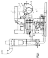
- the apparatus comprises a stationary carrier chassis 1 and a movable carrier chassis 10.
- the fixed frame 1 has the form of a bracket and carries at its end a mechanism 2 for driving a mixing tool 3.
- the mechanism 2 will be described in detail in relation to FIG. 5.
- the kneading tool 3 is rotated both around the X axis and around itself around the Y axis. .
- the mobile frame 10 is carried by the fixed frame 1 and actuated by means that allow it to go up and down.
- the frame 10 carries a support 11, on which a tank 12 is pivotally mounted.
- the fixed tool frame becomes mobile.
- the tank carrier frame being stationary or movable.
- the lid 4 has closable orifices for introducing into the tank 12 the various products to be mixed by mixing, such as sand, gypsum, admixtures, water or other.
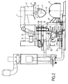
- the frame 10 When the mixing is completed, the frame 10 is brought into the lower position and the tank 12 rotated by 180 °, as shown in FIG. 2. The kneaded product then falls into a hopper or a conveyor which are not shown because they are not part of the invention.
- the apparatus according to the present invention therefore comprises two cleaning assemblies: a first for the interior of the tank 12, a second for cleaning the branches of the mixing tool 3.
- the tank 12 After being turned 180 ° to be emptied, the tank 12 is rotated 90 ° to occupy a horizontal position, its orifice being turned towards the apparatus, as shown in FIG.
- This lid carries at its center, rotatably mounted, a tube 26 which may be a hollow tube, said tube 26 carrying a set of brushes 27 conforming to the shape of the inner wall of the tank 12.
- the lid 20 comprises at its upper part an air inlet orifice 28 and at its lower part an air outlet orifice 29, connected to a duct for exhausting air + dust 41, this duct being telescopic to follow the movements of the lid 20 and connected to a suction and filtration device 40.
- the tube 26 is rotated by any suitable motor, so that the set of brushes 27 strongly rubs against the inner wall of the tank 12. The products and dust detached by the brushes 27 are sucked into the pipe 41.
- the tank 12 is then cleared of any trace of product.
- the tube 26 being hollow can be used to vaporize a little water or solvent to complete the brushing work.
- the second cleaning assembly has the function of cleaning the mixing tool 3.
- the kneading tool 3 passes between two parallel cylindrical brushes 30 and penetrates inside the box 31.
- the particles of kneaded product which had remained stuck to the branches of said tool 3 are detached and aspirated in the device 40.
- the longitudinal opening 33 of the box 31, between the two brushes 30, is masked by brushes son to prevent product particles may fall outside the box 31.
- the kneading tool is driven both by a circular movement and a rotational movement on itself, this double movement being obtained by a planetary type gear of the kneading tool on a central gear. These two movements are therefore mechanically linked.
- the tool 3 in a first step the tool 3 is presented so as to be parallel to the plane Z but slightly offset on the side, as shown in solid lines, then in a second step it is shifted so as to occupy a symmetrical position of the first, but on the other side of the Z plane, as shown in dashed lines.
- each side of the branch of the tool 3 is rubbed by the brushes 30 in two ways: once by being driven into the mass of the brush and a second time by the end of the bristles of the brush, this which gives an excellent cleaning. In general, to optimize its cleaning, the tool must be moved during this operation.
- Moving parallel to itself can only be achieved by rotating a certain angle around X in conjunction with a rotation in the opposite direction around Y.
- the drive mechanism of the tool 3 consists of two coaxial tubes 50 and 51; the tube 50 rotates about the X axis being driven by a pulley 52, while the tube 51 rotates around the shaft 50 being driven by a pulley 53.
- the tube 51 carries a pinion 54 which meshes with a pinion 55 which rotates about the axis Y and carries the shaft 56 of the tool 3.
Landscapes
- Chemical & Material Sciences (AREA)
- Chemical Kinetics & Catalysis (AREA)
- Engineering & Computer Science (AREA)
- Mechanical Engineering (AREA)
- Accessories For Mixers (AREA)
- Mixers Of The Rotary Stirring Type (AREA)
- Mixers With Rotating Receptacles And Mixers With Vibration Mechanisms (AREA)
- Grinding-Machine Dressing And Accessory Apparatuses (AREA)
- Sorption Type Refrigeration Machines (AREA)
- Processing Of Solid Wastes (AREA)
Abstract
Description
- La présente invention concerne un malaxeur à nettoyage automatique.
- De nouveaux produits à base de liants à prise rapide tels que gypse, bétons fins à hautes performances, résines, sont apparus récemment sur le marché et semblent avoir un avenir très prometteur.
- Ils présentent cependant des difficultés de mise en oeuvre très importantes pour leur fabrication industrielle :
- aucune trace de germe ne doit subsister ni dans la cuve de malaxage ni sur l'outil de malaxage parce que ces traces vont agir comme des accélérateurs de prise et modifier les performances du produit.
- L'encrassement des outils réduit leur efficacité et perturbe la qualité des mélanges en cas de détachement d'éléments.
- On a essayé de réaliser le malaxage désiré avec des malaxeurs utilisés en boulangerie c'est-à-dire constitués d'une cuve dont le volume intérieur est brassé par un outil de malaxage ou pale animé d'un double mouvement de rotation, le premier autour de l'axe de la cuve, le deuxième sur lui-même.
- Dans les dispositifs connus, le mouvement de rotation sur lui-même de l'outil de malaxage est obtenu par un engrenage planétaire.
- De tels malaxeurs ont de bonnes performances de malaxage, mais il s'est avéré impossible d'enlever de manière automatique absolument toute trace de mélange après une opération de malaxage ; une opération manuelle de nettoyage s'avérant indispensable.
- D'autres dispositifs de nettoyage consistent à projeter un liquide au moyen de buses dans l'enceinte formée par la cuve et le mécanisme de malaxage. Ce qui présente, dans la pratique, des zones mal nettoyées et nécessite parfois un séchage après nettoyage.
- La présente invention a donc pour premier objet de réaliser un malaxeur équipé de moyens de nettoyage automatique ne laissant aucune trace de produit ni sur les parois de la cuve ni sur l'outil de malaxage après une opération de malaxage.
- D'autre part, la présente invention comporte des moyens de réglage indépendant des deux vitesses de rotation de l'outil permettant d'optimiser chaque étape du malaxage et d'éviter les phénomènes d'usure en des lieux privilégiés de la cuve.
- De plus la présente invention se caractérise par le fait que le nettoyage est confiné, et donc sans pollutions, par étanchéité et aspiration.
- A titre d'exemple, non limitatif, et pour faciliter la compréhension de l'invention, on a représenté aux dessins annexés :
- Figure 1
- une vue schématique en coupe latérale d'un exemple de réalisation de l'invention en position de malaxage
- Figure 2
- une vue de l'appareil de la figure 1 en position de vidange de la cuve
- Figure 3
- une vue de l'appareil des figures 1 et 2 en position de nettoyage automatique
- Figure 4
- une vue schématique en plan illustrant les deux positions de l'outil de malaxage pendant son nettoyage
- Figure 5
- une vue de détail en coupe longitudinale illustrant le mécanisme de double rotation de l'outil de malaxage.
- En se reportant à ces figures, on voit que l'appareil selon la présente invention comporte un châssis porteur fixe 1 et un châssis porteur mobile 10.
- Le châssis fixe 1 a la forme d'une potence et porte à son extrémité un mécanisme 2 d'entraînement d'un outil de malaxage 3.
- Le mécanisme 2 sera décrit de façon détaillée en relation avec la figure 5. Grâce à ce mécanisme, l'outil de malaxage 3 est mis en rotation à la fois autour de l'axe X et sur lui-même autour de l'axe Y.
- Le châssis mobile 10 est porté par le châssis fixe 1 et actionné par des moyens qui lui permettent de monter et descendre.
- Le châssis 10 porte un support 11, sur lequel une cuve 12 est montée à pivotement.
- Lorsque le châssis 10 est en position haute, comme cela est représenté à la figure 1, le rebord supérieur de la cuve 4, qui est conique, vient s'engager dans le rebord inférieur également conique d'un couvercle 4, fixe, porté par le châssis 1.
- Dans une variante de conception, le châssis porte-outil fixe devient mobile. Le châssis porte-cuve étant fixe ou mobile.
- Dans cette position la cuve 12 est fermée de façon hermétique, de sorte qu'aucune poussière ne peut s'en échapper pendant le malaxage.
- Bien que cela ne soit pas représenté pour simplifier le dessin, le couvercle 4 comporte des orifices obturables permettant d'introduire dans la cuve 12 les divers produits devant être mélangés par malaxage, tels que sable, gypse, adjuvants, eau ou autres.
- Lorsque le malaxage est terminé le châssis 10 est amené en position basse et la cuve 12 pivotée de 180°, comme cela est représenté à la figure 2. le produit malaxé tombe alors dans une trémie ou un transporteur qui ne sont pas représentés parce qu'ils ne font pas partie de l'invention.
- Lorsque la cuve est vide, il reste une quantité non négligeable de produits collés contre ses parois. De même, une certaine quantité de produit malaxé demeure collée aux branches de l'outil de malaxage 3.
- Il est impératif avant de procéder à une nouvelle opération de malaxage de nettoyer la cuve 12 et l'outil 3 de façon telle qu'il ne reste pas la plus infime parcelle de produit.
- Il s'est en effet avéré, lors d'essais avec des malaxeurs connus, que la moindre trace de produit constitue un germe accélérateur de prise tel que si on remplit à nouveau la cuve 12 il y aura un commencement de prise pendant le malaxage ce qui rendra impossible un malaxage homogène et rendra inutilisables les produits mis dans la cuve.
- L'appareil selon la présente invention comporte donc deux ensembles de nettoyage : un premier pour l'intérieur de la cuve 12, un deuxième pour nettoyer les branches de l'outil de malaxage 3.
- Après avoir été retournée de 180° pour être vidée, la cuve 12 est pivotée de 90° pour occuper une position horizontale, son orifice étant tourné vers l'appareil, comme cela est représenté à la figure 3.
- Un couvercle mobile 20, analogue au couvercle fixe 4, porté par un chariot 22 roulant entre des galets 23 et déplacé par un levier 24 mû par un vérin 25 vient fermer la cuve 12 de façon hermétique.
- Ce couvercle porte en son centre, monté à rotation, un tube 26 qui peut être un tube creux, ledit tube 26 portant un ensemble de brosses 27 épousant la forme de la paroi interne de la cuve 12.
- Le couvercle 20 comporte à sa partie haute un orifice d'entrée d'air 28 et à sa partie basse un orifice d'évacuation d'air 29, connecté à une canalisation d'évacuation d'air + poussières 41, cette canalisation étant télescopique pour suivre les mouvements du couvercle 20 et relié à un dispositif d'aspiration et de filtration 40.
- Le tube 26 est entraîné en rotation par tout moteur approprié, de sorte que l'ensemble de brosses 27 frotte énergiquement contre la paroi interne de la cuve 12. Les produits et poussières détachés par les brosses 27 sont aspirés dans la canalisation 41.
- La cuve 12 est alors débarrassée de toute trace de produit.
- Le tube 26 étant creux peut servir à vaporiser un peu d'eau ou de solvant pour compléter le travail de brossage.
- Le deuxième ensemble de nettoyage a pour fonction de nettoyer l'outil malaxeur 3.
- Il est constitué de brosses 30 disposées à l'ouverture d'un caisson 31 porté par un chariot 32. L'enceinte du caisson 31 est reliée par une canalisation télescopique 42 au dispositif d'aspiration 40.
- Dans l'exemple représenté, lorsque le chariot 32 avance, l'outil de malaxage 3 passe entre deux brosses cylindriques parallèles 30 et pénètre à l'intérieur du caisson 31. Les particules de produit malaxé qui étaient restées collées aux branches dudit outil 3 sont détachées et aspirées dans le dispositif 40.
- De préférence, l'ouverture longitudinale 33 du caisson 31, entre les deux brosses 30, est masquée par des fils de brosses pour empêcher que des particules de produit puissent tomber à l'extérieur du caisson 31.
- Dans les appareils de malaxage connus, tels par exemple que ceux employés en boulangerie, l'outil de malaxage est animé à la fois d'un mouvement circulaire et d'un mouvement de rotation sur lui-même, ce double mouvement étant obtenu par un engrenage type planétaire du pignon de l'outil de malaxage sur un pignon central. Ces deux mouvements sont donc mécaniquement liés.
- Selon un autre aspect de la présente invention, ces deux mouvements de rotation doivent être indépendants et cela pour deux raisons.
- La première pour adapter les vitesses relatives aux compositions et aux étapes successives du mélange et éviter la création de zones d'usure de la cuve. La seconde pour le mettre en position par rapport à l'outil de brossage, comme représenté à la figure 4.
- Pour obtenir un bon brossage de l'outil 3, il faut qu'il se présente dans l'ouverture 33 en étant parallèle au plan Z séparant les deux brosses 30; pour cela il faut pouvoir l'orienter par rotation autour de son axe Y, indépendamment de toute rotation autour de l'axe X.
- Comme cela est représenté à la figure 4, dans un premier temps l'outil 3 est présenté de façon à être parallèle au plan Z mais légèrement décalé sur le côté, comme cela est représenté en traits pleins, puis dans un deuxième temps il est décalé de façon à occuper une position symétrique de la première, mais de l'autre côté du plan Z, comme cela est représenté en pointillés.
- On obtient ainsi que chaque côté de la branche de l'outil 3 est frotté par les brosses 30 de deux façons : une fois en étant enfoncé dans la masse de la brosse et une deuxième fois par l'extrémité des poils de la brosse, ce qui donne un excellent nettoyage.
D'une manière générale, pour optimiser son nettoyage, l'outil doit pouvoir être déplacé au cours de cette opération. - Le déplacement parallèlement à lui-même ne peut être obtenu qu'en procédant à une rotation d'un certain angle autour de X conjuguée à un pivotement en sens inverse autour de Y.
- Bien évidemment, cela ne peut pas être obtenu avec des moyens d'entraînement par engrenages planétaires, ou tout autre liaison mécanique synchronisée.
- En se reportant à la figure 5 on voit que le mécanisme d'entraînement de l'outil 3 est constitué de deux tubes co-axiaux 50 et 51 ; le tube 50 tourne autour de l'axe X en étant entraîné par une poulie 52, tandis que le tube 51 tourne autour de l'arbre 50 en étant entraîné par une poulie 53.
- Le tube 51 porte un pignon 54 qui engrène sur un pignon 55 qui tourne autour de l'axe Y et porte l'arbre 56 de l'outil 3.
- Le fait que les vitesses de rotation de l'outil sur lui-même et selon l'axe de la cuve sont ajustables indépendamment et en continu au cours du cycle de malaxage permet le réglage de différentes étapes de malaxage en particulier en cas d'ajout de fibres.
Claims (9)
- Malaxeur du type comportant une cuve (12) dans laquelle se déplace un outil de malaxage (3) animé d'un double mouvement, l'un circulaire autour de l'axe (X) de la cuve (12), et l'autre de rotation sur lui-même autour de son axe (Y), caractérisé par le fait qu'il comporte des moyens réalisant automatiquement, et séparément après chaque malaxage, le nettoyage de la cuve (12) et celui de l'outil de malaxage (3).
- Dispositif selon la revendication 1, dans lequel les deux mouvements de rotation de l'outil sont indépendants.
- Malaxeur selon les revendications 1 et 2, caractérisé par le fait qu'il comporte un premier châssis (1) fixe portant l'outil de malaxage (3) et son mécanisme (2) d'entraînement; un deuxième châssis (10), mobile, portant à pivotement une cuve (12) de telle sorte que la dite cuve (12) puisse occuper trois positions par rapport à l'outils de malaxage: une position haute de travail dans laquelle elle est obturée hermétiquement par un couvercle (4) porté par le premier châssis (1); une deuxième position, basse, dans laquelle elle est séparée de l'outil et pivotée pour être vidée ; une troisième position dans laquelle elle est pivotée face à des moyens de nettoyage automatique et obturée.
- Malaxeur selon les revendications 1,2 et 3, caractérisé par le fait que le châssis porte-outil (1) est mobile.
- Malaxeur selon les revendications 1, 2, 3 et 4, dans lequel les moyens de nettoyage automatique comportent : un couvercle (20), porté par un chariot (22) de façon à pouvoir venir obturer hermétiquement la cuve (12), ledit couvercle portant en son centre un axe rotatif (26) lui-même portant un ensemble de brosses (27) épousant la forme de la paroi interne de la cuve (12), ledit couvercle (20) étant muni, de moyens d'extraction (29) des poussières.
- Dispositif selon les revendications 1 à 5 dans lequel le dispositif de nettoyage des branches de l'outil de malaxage (3) est constitué par un caisson mobile (31) dans lequel sont placées des brosses (30), ce caisson étant monté sur un chariot mobile (32) de façon à faire passer l'organe de malaxage entre les brosses (30).
- Dispositif selon les revendications 1à 6 dans lequel l'outil de malaxage (3) est animé d'un mouvement dans son caisson de nettoyage pour faciliter l'opération de brossage.
- Dispositif selon l'une quelconque des revendications 1 à 7 dans lequel les vitesses de rotation de l'outil sur lui même et selon l'axe de la cuve sont ajustables indépendamment et en continu au cours du cycle de malaxage selon les étapes de mélangeage en particulier en cas d'ajout de fibres.
- Dispositif selon l'une quelconque des revendications 1 à 7 dans lequel le mécanisme (2) d'entraînement de l'outil de malaxage (3) est constitué de deux arbres co-axiaux (50, 51) l'un tournant autour de l'axe (X) de la cuve (12), l'autre tournant autour de l'axe (50) comportant un pignon (54) engrenant sur un autre pignon (55) tournant autour de l'axe (Y) et portant l'arbre (56) de l'outil de malaxage (3).
Applications Claiming Priority (1)
| Application Number | Priority Date | Filing Date | Title |
|---|---|---|---|
| FR0513495A FR2895685B1 (fr) | 2005-12-30 | 2005-12-30 | Malaxeur a nettoyage automatique |
Publications (2)
| Publication Number | Publication Date |
|---|---|
| EP1803496A1 true EP1803496A1 (fr) | 2007-07-04 |
| EP1803496B1 EP1803496B1 (fr) | 2008-07-30 |
Family
ID=37103227
Family Applications (1)
| Application Number | Title | Priority Date | Filing Date |
|---|---|---|---|
| EP06292058A Not-in-force EP1803496B1 (fr) | 2005-12-30 | 2006-12-27 | Malaxeur à nettoyage automatique |
Country Status (4)
| Country | Link |
|---|---|
| EP (1) | EP1803496B1 (fr) |
| AT (1) | ATE402756T1 (fr) |
| DE (1) | DE602006002016D1 (fr) |
| FR (1) | FR2895685B1 (fr) |
Cited By (2)
| Publication number | Priority date | Publication date | Assignee | Title |
|---|---|---|---|---|
| DE202014010060U1 (de) | 2014-12-19 | 2015-03-09 | Elektrowerkzeuge Gmbh Eibenstock | Mischstation |
| CN113385126A (zh) * | 2021-05-08 | 2021-09-14 | 章龙生 | 一种幻彩合成云母片生产预处理装置 |
Families Citing this family (1)
| Publication number | Priority date | Publication date | Assignee | Title |
|---|---|---|---|---|
| CN111773952A (zh) * | 2020-07-09 | 2020-10-16 | 安徽森普新型材料发展有限公司 | 复合型减水剂独立混合搅拌机构 |
Citations (5)
| Publication number | Priority date | Publication date | Assignee | Title |
|---|---|---|---|---|
| US1475978A (en) * | 1922-12-08 | 1923-12-04 | Westerman Frederick | Beater |
| US1628632A (en) * | 1926-05-10 | 1927-05-10 | Gypsum Engineering & Mfg Co | Continuous self-cleaning mixer |
| FR998658A (fr) * | 1949-09-30 | 1952-01-22 | Applic Mecaniques Speciales Et | Batteur-mélangeur |
| FR2402471A1 (fr) * | 1977-09-07 | 1979-04-06 | Euro Machines | Dispositif pour la fabrication de melanges divers |
| FR2849788A1 (fr) * | 2003-01-14 | 2004-07-16 | Hognon Sa | Melangeur |
-
2005
- 2005-12-30 FR FR0513495A patent/FR2895685B1/fr not_active Expired - Fee Related
-
2006
- 2006-12-27 EP EP06292058A patent/EP1803496B1/fr not_active Not-in-force
- 2006-12-27 DE DE602006002016T patent/DE602006002016D1/de not_active Expired - Fee Related
- 2006-12-27 AT AT06292058T patent/ATE402756T1/de not_active IP Right Cessation
Patent Citations (5)
| Publication number | Priority date | Publication date | Assignee | Title |
|---|---|---|---|---|
| US1475978A (en) * | 1922-12-08 | 1923-12-04 | Westerman Frederick | Beater |
| US1628632A (en) * | 1926-05-10 | 1927-05-10 | Gypsum Engineering & Mfg Co | Continuous self-cleaning mixer |
| FR998658A (fr) * | 1949-09-30 | 1952-01-22 | Applic Mecaniques Speciales Et | Batteur-mélangeur |
| FR2402471A1 (fr) * | 1977-09-07 | 1979-04-06 | Euro Machines | Dispositif pour la fabrication de melanges divers |
| FR2849788A1 (fr) * | 2003-01-14 | 2004-07-16 | Hognon Sa | Melangeur |
Cited By (3)
| Publication number | Priority date | Publication date | Assignee | Title |
|---|---|---|---|---|
| DE202014010060U1 (de) | 2014-12-19 | 2015-03-09 | Elektrowerkzeuge Gmbh Eibenstock | Mischstation |
| EP3047900A1 (fr) | 2014-12-19 | 2016-07-27 | Elektrowerkzeuge GmbH Eibenstock | Station de melange |
| CN113385126A (zh) * | 2021-05-08 | 2021-09-14 | 章龙生 | 一种幻彩合成云母片生产预处理装置 |
Also Published As
| Publication number | Publication date |
|---|---|
| ATE402756T1 (de) | 2008-08-15 |
| DE602006002016D1 (de) | 2008-09-11 |
| FR2895685A1 (fr) | 2007-07-06 |
| FR2895685B1 (fr) | 2008-02-29 |
| EP1803496B1 (fr) | 2008-07-30 |
Similar Documents
| Publication | Publication Date | Title |
|---|---|---|
| EP2754484A1 (fr) | Mélangeur à cuve conique tournante | |
| EP1959809B1 (fr) | Dispositif de decolmatage de filtre pour aspirateur | |
| EP1803496B1 (fr) | Malaxeur à nettoyage automatique | |
| CN211361904U (zh) | 一种阀门通道喷砂装置 | |
| EP1850952B1 (fr) | Melangeur a outi ls de melange entraînes par la rotation de la cuve | |
| EP1035956B1 (fr) | Dispositif de surfacage | |
| FR2808120A1 (fr) | Procede et dispositif pour le traitement du substrat d'un circuit integre ou d'un produit analogue en cours de fabrication | |
| FR2638671A1 (fr) | Dispositif et procede de decoupe de pieces irradiees par jet d'eau sous pression | |
| FR2700495A1 (fr) | Procédé et dispositif pour la préparation de fûts métalliques usagés en vue de faciliter leur manutention et leur recyclage. | |
| CN213315219U (zh) | 一种造粒机喷头快速拆卸装置及其造粒机 | |
| EP0172854A1 (fr) | Procede de traitement par brassage en vrac de pieces brutes moulees ou usinees et machine pour la mise en oeuvre de ce procede. | |
| FR2802848A1 (fr) | Procede pour preparer un melange et appareil, tel que betonniere, s'y rapportant | |
| FR2859715A1 (fr) | Dispositif de nettoyage d'un silo a fond sensiblement plat destine a stocker des grains s'ecoulant naturellement par gravite | |
| EP0378025A1 (fr) | Appareil et procédé de nettoyage d'une surface horizontale | |
| JPS605964Y2 (ja) | 鋳物砂の混練ミキサ | |
| CN213255999U (zh) | 一种纸制品包装粘合剂原料清洗装置 | |
| CN219822933U (zh) | 一种物料真空吸料机构 | |
| CN221638268U (zh) | 一种干法脱硫剂精细研磨装置 | |
| CN219686071U (zh) | 一种陶瓷煲生产用练泥仪器 | |
| CN221696552U (zh) | 一种滚筒式喷砂机 | |
| FR2715329A1 (fr) | Machine de fragmentation pour recyclage de pièces en matière plastique. | |
| FR2777875A1 (fr) | Installation de vidage de futs contenant un produit pateux | |
| FR2732238A1 (fr) | Melangeur a cuve tournante | |
| EP0749783B1 (fr) | Machine de fragmentation de pièces en matière plastique | |
| EP4704585A1 (fr) | Dispositif de broyage d'un produit pateux ou en poudre et en suspension |
Legal Events
| Date | Code | Title | Description |
|---|---|---|---|
| PUAI | Public reference made under article 153(3) epc to a published international application that has entered the european phase |
Free format text: ORIGINAL CODE: 0009012 |
|
| AK | Designated contracting states |
Kind code of ref document: A1 Designated state(s): AT BE BG CH CY CZ DE DK EE ES FI FR GB GR HU IE IS IT LI LT LU LV MC NL PL PT RO SE SI SK TR |
|
| AX | Request for extension of the european patent |
Extension state: AL BA HR MK YU |
|
| GRAP | Despatch of communication of intention to grant a patent |
Free format text: ORIGINAL CODE: EPIDOSNIGR1 |
|
| 17P | Request for examination filed |
Effective date: 20071220 |
|
| AKX | Designation fees paid |
Designated state(s): AT BE BG CH CY CZ DE DK EE ES FI FR GB GR HU IE IS IT LI LT LU LV MC NL PL PT RO SE SI SK TR |
|
| GRAS | Grant fee paid |
Free format text: ORIGINAL CODE: EPIDOSNIGR3 |
|
| GRAA | (expected) grant |
Free format text: ORIGINAL CODE: 0009210 |
|
| AK | Designated contracting states |
Kind code of ref document: B1 Designated state(s): AT BE BG CH CY CZ DE DK EE ES FI FR GB GR HU IE IS IT LI LT LU LV MC NL PL PT RO SE SI SK TR |
|
| REG | Reference to a national code |
Ref country code: GB Ref legal event code: FG4D Free format text: NOT ENGLISH |
|
| REG | Reference to a national code |
Ref country code: CH Ref legal event code: EP |
|
| REF | Corresponds to: |
Ref document number: 602006002016 Country of ref document: DE Date of ref document: 20080911 Kind code of ref document: P |
|
| REG | Reference to a national code |
Ref country code: IE Ref legal event code: FG4D Free format text: LANGUAGE OF EP DOCUMENT: FRENCH |
|
| PG25 | Lapsed in a contracting state [announced via postgrant information from national office to epo] |
Ref country code: IS Free format text: LAPSE BECAUSE OF FAILURE TO SUBMIT A TRANSLATION OF THE DESCRIPTION OR TO PAY THE FEE WITHIN THE PRESCRIBED TIME-LIMIT Effective date: 20081130 Ref country code: LT Free format text: LAPSE BECAUSE OF FAILURE TO SUBMIT A TRANSLATION OF THE DESCRIPTION OR TO PAY THE FEE WITHIN THE PRESCRIBED TIME-LIMIT Effective date: 20080730 Ref country code: NL Free format text: LAPSE BECAUSE OF FAILURE TO SUBMIT A TRANSLATION OF THE DESCRIPTION OR TO PAY THE FEE WITHIN THE PRESCRIBED TIME-LIMIT Effective date: 20080730 |
|
| PG25 | Lapsed in a contracting state [announced via postgrant information from national office to epo] |
Ref country code: PT Free format text: LAPSE BECAUSE OF FAILURE TO SUBMIT A TRANSLATION OF THE DESCRIPTION OR TO PAY THE FEE WITHIN THE PRESCRIBED TIME-LIMIT Effective date: 20081230 Ref country code: LV Free format text: LAPSE BECAUSE OF FAILURE TO SUBMIT A TRANSLATION OF THE DESCRIPTION OR TO PAY THE FEE WITHIN THE PRESCRIBED TIME-LIMIT Effective date: 20080730 Ref country code: AT Free format text: LAPSE BECAUSE OF FAILURE TO SUBMIT A TRANSLATION OF THE DESCRIPTION OR TO PAY THE FEE WITHIN THE PRESCRIBED TIME-LIMIT Effective date: 20080730 Ref country code: BG Free format text: LAPSE BECAUSE OF FAILURE TO SUBMIT A TRANSLATION OF THE DESCRIPTION OR TO PAY THE FEE WITHIN THE PRESCRIBED TIME-LIMIT Effective date: 20081030 Ref country code: ES Free format text: LAPSE BECAUSE OF FAILURE TO SUBMIT A TRANSLATION OF THE DESCRIPTION OR TO PAY THE FEE WITHIN THE PRESCRIBED TIME-LIMIT Effective date: 20081110 Ref country code: FI Free format text: LAPSE BECAUSE OF FAILURE TO SUBMIT A TRANSLATION OF THE DESCRIPTION OR TO PAY THE FEE WITHIN THE PRESCRIBED TIME-LIMIT Effective date: 20080730 Ref country code: SI Free format text: LAPSE BECAUSE OF FAILURE TO SUBMIT A TRANSLATION OF THE DESCRIPTION OR TO PAY THE FEE WITHIN THE PRESCRIBED TIME-LIMIT Effective date: 20080730 |
|
| REG | Reference to a national code |
Ref country code: IE Ref legal event code: FD4D |
|
| PG25 | Lapsed in a contracting state [announced via postgrant information from national office to epo] |
Ref country code: DK Free format text: LAPSE BECAUSE OF FAILURE TO SUBMIT A TRANSLATION OF THE DESCRIPTION OR TO PAY THE FEE WITHIN THE PRESCRIBED TIME-LIMIT Effective date: 20080730 Ref country code: EE Free format text: LAPSE BECAUSE OF FAILURE TO SUBMIT A TRANSLATION OF THE DESCRIPTION OR TO PAY THE FEE WITHIN THE PRESCRIBED TIME-LIMIT Effective date: 20080730 Ref country code: IE Free format text: LAPSE BECAUSE OF FAILURE TO SUBMIT A TRANSLATION OF THE DESCRIPTION OR TO PAY THE FEE WITHIN THE PRESCRIBED TIME-LIMIT Effective date: 20080730 |
|
| PG25 | Lapsed in a contracting state [announced via postgrant information from national office to epo] |
Ref country code: SK Free format text: LAPSE BECAUSE OF FAILURE TO SUBMIT A TRANSLATION OF THE DESCRIPTION OR TO PAY THE FEE WITHIN THE PRESCRIBED TIME-LIMIT Effective date: 20080730 Ref country code: RO Free format text: LAPSE BECAUSE OF FAILURE TO SUBMIT A TRANSLATION OF THE DESCRIPTION OR TO PAY THE FEE WITHIN THE PRESCRIBED TIME-LIMIT Effective date: 20080730 Ref country code: CZ Free format text: LAPSE BECAUSE OF FAILURE TO SUBMIT A TRANSLATION OF THE DESCRIPTION OR TO PAY THE FEE WITHIN THE PRESCRIBED TIME-LIMIT Effective date: 20080730 |
|
| PLBE | No opposition filed within time limit |
Free format text: ORIGINAL CODE: 0009261 |
|
| STAA | Information on the status of an ep patent application or granted ep patent |
Free format text: STATUS: NO OPPOSITION FILED WITHIN TIME LIMIT |
|
| BERE | Be: lapsed |
Owner name: PELERIN ATELIERS DE CONSTRUCTIONS D'ORCAMPS Effective date: 20081231 |
|
| 26N | No opposition filed |
Effective date: 20090506 |
|
| PG25 | Lapsed in a contracting state [announced via postgrant information from national office to epo] |
Ref country code: MC Free format text: LAPSE BECAUSE OF NON-PAYMENT OF DUE FEES Effective date: 20081231 |
|
| PG25 | Lapsed in a contracting state [announced via postgrant information from national office to epo] |
Ref country code: IT Free format text: LAPSE BECAUSE OF FAILURE TO SUBMIT A TRANSLATION OF THE DESCRIPTION OR TO PAY THE FEE WITHIN THE PRESCRIBED TIME-LIMIT Effective date: 20080730 |
|
| PG25 | Lapsed in a contracting state [announced via postgrant information from national office to epo] |
Ref country code: BE Free format text: LAPSE BECAUSE OF NON-PAYMENT OF DUE FEES Effective date: 20081231 |
|
| PG25 | Lapsed in a contracting state [announced via postgrant information from national office to epo] |
Ref country code: DE Free format text: LAPSE BECAUSE OF NON-PAYMENT OF DUE FEES Effective date: 20090701 |
|
| PGFP | Annual fee paid to national office [announced via postgrant information from national office to epo] |
Ref country code: FR Payment date: 20081231 Year of fee payment: 3 |
|
| PG25 | Lapsed in a contracting state [announced via postgrant information from national office to epo] |
Ref country code: SE Free format text: LAPSE BECAUSE OF FAILURE TO SUBMIT A TRANSLATION OF THE DESCRIPTION OR TO PAY THE FEE WITHIN THE PRESCRIBED TIME-LIMIT Effective date: 20081030 |
|
| PG25 | Lapsed in a contracting state [announced via postgrant information from national office to epo] |
Ref country code: PL Free format text: LAPSE BECAUSE OF FAILURE TO SUBMIT A TRANSLATION OF THE DESCRIPTION OR TO PAY THE FEE WITHIN THE PRESCRIBED TIME-LIMIT Effective date: 20080730 |
|
| PG25 | Lapsed in a contracting state [announced via postgrant information from national office to epo] |
Ref country code: HU Free format text: LAPSE BECAUSE OF FAILURE TO SUBMIT A TRANSLATION OF THE DESCRIPTION OR TO PAY THE FEE WITHIN THE PRESCRIBED TIME-LIMIT Effective date: 20090131 Ref country code: CY Free format text: LAPSE BECAUSE OF FAILURE TO SUBMIT A TRANSLATION OF THE DESCRIPTION OR TO PAY THE FEE WITHIN THE PRESCRIBED TIME-LIMIT Effective date: 20080730 Ref country code: LU Free format text: LAPSE BECAUSE OF NON-PAYMENT OF DUE FEES Effective date: 20081227 |
|
| PG25 | Lapsed in a contracting state [announced via postgrant information from national office to epo] |
Ref country code: TR Free format text: LAPSE BECAUSE OF FAILURE TO SUBMIT A TRANSLATION OF THE DESCRIPTION OR TO PAY THE FEE WITHIN THE PRESCRIBED TIME-LIMIT Effective date: 20080730 |
|
| REG | Reference to a national code |
Ref country code: FR Ref legal event code: ST Effective date: 20100831 |
|
| PG25 | Lapsed in a contracting state [announced via postgrant information from national office to epo] |
Ref country code: GR Free format text: LAPSE BECAUSE OF FAILURE TO SUBMIT A TRANSLATION OF THE DESCRIPTION OR TO PAY THE FEE WITHIN THE PRESCRIBED TIME-LIMIT Effective date: 20081031 Ref country code: FR Free format text: LAPSE BECAUSE OF NON-PAYMENT OF DUE FEES Effective date: 20091231 |
|
| REG | Reference to a national code |
Ref country code: CH Ref legal event code: PL |
|
| GBPC | Gb: european patent ceased through non-payment of renewal fee |
Effective date: 20101227 |
|
| PG25 | Lapsed in a contracting state [announced via postgrant information from national office to epo] |
Ref country code: CH Free format text: LAPSE BECAUSE OF NON-PAYMENT OF DUE FEES Effective date: 20101231 Ref country code: LI Free format text: LAPSE BECAUSE OF NON-PAYMENT OF DUE FEES Effective date: 20101231 |
|
| PG25 | Lapsed in a contracting state [announced via postgrant information from national office to epo] |
Ref country code: GB Free format text: LAPSE BECAUSE OF NON-PAYMENT OF DUE FEES Effective date: 20101227 |