EP1803655B1 - Sac en matière plastique et pile de sacs contenant un tel sac - Google Patents
Sac en matière plastique et pile de sacs contenant un tel sac Download PDFInfo
- Publication number
- EP1803655B1 EP1803655B1 EP05027424A EP05027424A EP1803655B1 EP 1803655 B1 EP1803655 B1 EP 1803655B1 EP 05027424 A EP05027424 A EP 05027424A EP 05027424 A EP05027424 A EP 05027424A EP 1803655 B1 EP1803655 B1 EP 1803655B1
- Authority
- EP
- European Patent Office
- Prior art keywords
- strip
- bag
- holding device
- stack
- opening end
- Prior art date
- Legal status (The legal status is an assumption and is not a legal conclusion. Google has not performed a legal analysis and makes no representation as to the accuracy of the status listed.)
- Expired - Lifetime
Links
Images

Classifications
-
- B—PERFORMING OPERATIONS; TRANSPORTING
- B65—CONVEYING; PACKING; STORING; HANDLING THIN OR FILAMENTARY MATERIAL
- B65D—CONTAINERS FOR STORAGE OR TRANSPORT OF ARTICLES OR MATERIALS, e.g. BAGS, BARRELS, BOTTLES, BOXES, CANS, CARTONS, CRATES, DRUMS, JARS, TANKS, HOPPERS, FORWARDING CONTAINERS; ACCESSORIES, CLOSURES, OR FITTINGS THEREFOR; PACKAGING ELEMENTS; PACKAGES
- B65D33/00—Details of, or accessories for, sacks or bags
- B65D33/14—Suspension means
-
- B—PERFORMING OPERATIONS; TRANSPORTING
- B65—CONVEYING; PACKING; STORING; HANDLING THIN OR FILAMENTARY MATERIAL
- B65D—CONTAINERS FOR STORAGE OR TRANSPORT OF ARTICLES OR MATERIALS, e.g. BAGS, BARRELS, BOTTLES, BOXES, CANS, CARTONS, CRATES, DRUMS, JARS, TANKS, HOPPERS, FORWARDING CONTAINERS; ACCESSORIES, CLOSURES, OR FITTINGS THEREFOR; PACKAGING ELEMENTS; PACKAGES
- B65D33/00—Details of, or accessories for, sacks or bags
- B65D33/001—Blocks, stacks or like assemblies of bags
-
- B—PERFORMING OPERATIONS; TRANSPORTING
- B65—CONVEYING; PACKING; STORING; HANDLING THIN OR FILAMENTARY MATERIAL
- B65D—CONTAINERS FOR STORAGE OR TRANSPORT OF ARTICLES OR MATERIALS, e.g. BAGS, BARRELS, BOTTLES, BOXES, CANS, CARTONS, CRATES, DRUMS, JARS, TANKS, HOPPERS, FORWARDING CONTAINERS; ACCESSORIES, CLOSURES, OR FITTINGS THEREFOR; PACKAGING ELEMENTS; PACKAGES
- B65D33/00—Details of, or accessories for, sacks or bags
- B65D33/007—Details of, or accessories for, sacks or bags for facilitating the separation of the two walls, e.g. walls of inequal height, tabs; for maintaining the mouth of the sack or bag open
Definitions
- the present invention relates to a plastic carrier bag and a bag stack comprising a plurality of plastic carrier bags according to the invention.
- Plastic carrier bags are widely used in retail and wholesale. They have to be stored space-saving and must always be available to the user in the same reliability in large numbers. For this purpose, pocket stacks have established themselves, as they are regularly found, for example, vegetable counters of supermarkets. Such bag stacks can be hung, for example, in suitable stand devices in order to be available to the user. Generic bag stacks can be found in the two British Patents GB 2 391 538 B and GB 2 395 938 B described.
- the bag stacks disclosed in these documents comprise a plurality of plastic carrier bags which include a front and a back wall, the front and rear panels defining a bag body having a closed bottom end and closed sides and an opening end and two spaced gripping pieces.
- the front and rear walls each comprise an approximately central center strip, wherein the rear strip of the front pocket is always connected to the front strip of the underlying pocket separable.
- the carrier bags are separably connected to a holding or fastening device arranged between two grips. This fastening device accordingly has separable weakened areas both with both handles and with the upper end of the front and rear center strips the shopping bags.
- the present invention therefore an object of the invention to provide bag stacks available that ensure reliable handling and a flexible tearing of each bag pocket, especially for the last or lowermost pockets of a bag stack, the mass production to be unproblematic and completely automated can be.
- the invention was also based on the object, a To provide plastic carrier bag designed in such a way that it can be used in a bag stack that meets the above requirements.
- a plastic carrier bag was found, hereinafter also referred to as the first embodiment comprising a front wall and a rear wall, wherein the front and rear walls define a bag body having a substantially closed bottom end and at least partially closed sides and an at least partially open, opposite the bottom end opening end, two spaced apart grips, and at least one holding device for the carrier bag, wherein the front wall has a, in particular integrally connected, front strip which extends between the two grips away from the opening end, and wherein the front and rear strip and the rear wall has an, in particular integrally connected, rear strip which extends between the two gripping pieces away from the opening end, and wherein the front wall and / or the rear wall in each case via the located between the two grips opening end of front or rear wall are separably connected to the holding device via at least one weakening or perforation, wherein the front and / or the rear strip in each case via the located between the two grips opening end of the front or rear wall with the holding device for min at least one weakening or
- An embodiment of the invention may accordingly be designed in such a way that the front and the rear strip and the holding device are present separately or separably connected side by side, wherein the holding device may have, for example via a suitable opening or a penetration to the bag or the bag stack to hang on a stand device.
- the holding device may have, for example via a suitable opening or a penetration to the bag or the bag stack to hang on a stand device.
- the lateral connection sections can basically begin in any orientation on the bracket section connecting these connection sections, as long as it is ensured that a separable connection with the bag body or the front and / or rear wall can be received.
- these lateral connecting sections can be arranged, for example, perpendicular to the strap section, which preferably runs transversely to the longitudinal axis of the pocket. While in this case the lateral connecting portions have weakening areas in the region of the opening edge, the front or rear strip, in particular at the end opposite the opening end, has a separable connection or weakening area with the bow section connecting the lateral connecting sections.
- the weakening or perforation areas between the holding device, in particular the lateral connecting arms and the pocket body or the front or rear of the carrying bag can hereby lie in the region or at the level of the opening edge, above the opening edge or even below the opening edge, i. taken in the bag body.
- the perforation areas are arranged slightly above the opening edge.
- a plastic carrier bag hereinafter also called second embodiment, comprising a front wall and a rear wall, wherein the front and rear walls define a bag body with a substantially closed bottom end and at least partially closed sides and an at least partially open mouth end opposite the bottom end, two gripping pieces spaced apart from each other, and at least one holding device for the carrying case, the front wall comprising a front strip extending between the two handles away from the opening end, the rear wall comprising a rear strip which extends extends between the two gripping pieces away from the opening end, wherein the holding device is connected to at least one connecting portion via weakening or perforation regions separable connected to the front and / or rear strip, wob ei the holding device forms at least two, in particular symmetrical, holding openings together with the front and / or rear strip and wherein the holding device has at least two lateral connecting sections to the front and / or rear strip and a connecting portion connecting these strap sections, and wherein the front and / or or the
- the holding device is present connected to at least three spaced connecting portions via weakening or perforation separable with the front and / or rear strip.
- This can be accomplished, for example, in that the portion of the front or rear strip opposite the opening end is detachably connected to the holding device at a first portion is and that the holding device has extending toward the opening end portions which form a separable connection closer to the opening end with the front and rear strips.
- the front or rear strip is present only at a single point or on a single connecting portion, in particular at the opposite end of the opening end of the front and rear strips separably connected to these.
- Such a holding device may for example have a hole or an opening for inserting a punch-through arm of a St Svorrichtug.
- the plastic carrier bags according to the invention are accordingly distinguished by the fact that they no longer have separable connection points or sections with the grips. While in the first embodiment of the plastic carrying bag according to the invention, the holding device has separable connection areas with the opening end of the bag body and in particular also with the front and / or rear strip, the second embodiment of the plastic carrier bag according to the invention has a holding device, the exclusively separable connection areas with the front and / or. or rear strip.
- the separable connection between the front strip and the holding device and / or the rear strip and the holding device imd / or the opening end of the front and / or rear wall is accomplished with the holding device via at least one weakening or perforation.
- the holding device is preferably present between the spaced handles above the opening end.
- the front and / or the rear strip is or are separably connected to the holding device at the region opposite the opening end.
- This area is generally the topmost portion of the front and / or back strip, for example, when the carrier bag is suspended from a dispenser.
- the attachment of the plastic carrier bag via suitable gripping arms of the dispensing device is achieved by means of the holding device, which provides suitable engagement openings.
- the first embodiment of the carrying bag according to the invention is characterized in that the holding device together with the front and / or rear strip and the opening end forms at least two, in particular symmetrical, holding openings.
- the carrier bags according to the invention are characterized in a particularly preferred embodiment in that at least a portion of front and / or rear strip is dimensioned transversely to the longitudinal axis of the carrier bag narrower than a directly or indirectly extending in the direction away from the opening end portion of front or rear strips.
- the narrow portion of the front and / or rear strip is adjacent to the opening end.
- a narrower portion or a recess or indentation By having the front and / or rear strip, but in particular the front strip of a carrying bag, a narrower portion or a recess or indentation, a tearing of the pocket wall can be completely prevented.
- the above-described measure is particularly noticeable in such carrying bags according to the invention, in which the front and rear strips are each made in one piece with or made of the same material as the front or rear wall. It has proven to be particularly effective to provide the indentation or narrow section directly in the region of the front and rear strips adjoining the opening end.
- Inventive carrier bags are also characterized in particular by the weakening or perforation of the holding device with the front and / or Rear wall in the region of the opening end present.
- the weakened area or the weakening line is present essentially at the upper edge of the pocket body and particularly preferably in the course of the upper edge of the opening end of the pocket body.
- the weakening or perforation regions of the holding device with the front and / or rear wall are spaced from the opening end in the holding device.
- the weakened areas or lines of weakness are spaced from the upper edge or the upper edge of the opening end of the bag body and thus above it.
- the weakening or perforation area may also be below the opening end, e.g. let into the bag body, present.
- the upper region of the front and / or rear strip is preferably connected via one or more lines of weakness with the holding device, in particular a transverse strap portion of the holding device, separably connected.
- the separable weakening line may, for example, extend directly along the edge of the holding device or bow section of this preform facing the opening end, but may likewise be embedded in the latter or displaced toward the opening end in the upper region of the front or rear strip. In general, it is already sufficient to leave in the upper region of the front or rear strip only minimal connection points, which are easy to separate, and to have already completely severed the remaining area of the weakening line.
- the front and rear strips are blocked, in particular cold blocked before.
- the front and / or the rear strip and / or the holding device are formed substantially mirror-symmetrical, With such a design can be distributed evenly when removing the carrying bag from a stack of bags forces evenly, whereby material impairments and handling difficulties are further reduced.
- the grips are usually directly on the support body, in particular its opening end, on, are also in particular integrally connected to the bag body, and generally extend away from the opening end.
- a pocket stack comprising a plurality of arranged in the stack according to the invention carrier bags according to the first embodiment or according to the second embodiment, wherein the rear strip of a bag is separably connected in the stack with the front Strip the subsequent pocket in the stack.
- a plurality of carrier bags according to the invention comprises, for example, stacks of ten or more, in particular 100 or more stacked carrier bags.
- a stack may also include 1000 or more pockets. In the bag stacks according to the invention thus can be opened by pulling the front strip of a front pocket, the underlying pocket on the separable connection of the rear strip of the front pocket with the front strip of the underlying bag.
- connection of the front pocket with the holding device is released by pulling on the front strip of the front pocket.
- the separable connection between the rear strip of the front pocket and the front strip of the subsequent pocket is released by further pulling.
- the holding devices of the plastic bag together form the holding device for this stack.
- the holding devices are made of the same sheet material as the bag bodies and the handles, and thus usually have the same thickness and texture. Conveniently, the holding devices are locked in the stack
- the rear strip of a pocket in the stack is detachably connected to the front strip of the subsequent pocket in the stack at a strip-to-strip connection area, in particular connection point.
- the bag stacks according to the invention are preferably characterized in that the holding device and the weakening and perforating are designed in such a way that by pulling the front strip to remove the frontmost bag from the stack, the weakening or perforation of this bag give rather than the separable connection of the back strip of this bag with the front strip of the subsequent bag.
- front and rear strips are formed of the same material as the respective front and rear walls.
- the front and / or rear wall of a carrying bag according to the invention are designed to be multi-layered at least in some areas and can be used, for example, as a freezer or cooling bag.
- at least one such carrying bag is present in a pocket stack according to the invention.
- all the carrier bags of such a bag stack are equipped with such carrier bags. In general, it is sufficient to equip the front and / or rear wall in two layers.
- the holding device of the stack can accordingly be formed from a plurality of layers of film material of the front and / or rear wall.
- connection of the rear strip of a carrying bag with the front strip of the subsequent carrying bag of the bag stack is preferably accessed on a suitable adhesive.
- a suitable adhesive for the connection of the rear strip of a carrying bag with the front strip of the subsequent carrying bag of the bag stack.
- the rear side of the rear strip and the front side of the front strip of the subsequent pocket to undergo a corona treatment at least in some areas, in order to then compress them in particular.
- the material of the rear strip is pressed into a present in the front strip of the subsequent carrying bag indentation
- the front and rear strips of the plastic carrier bago present in this stack in particular in the upper region, can be locked together, in particular cold-blocked.
- the inventive plastic carrier bags present in the pocket stack according to the invention are preferably made of polyolefins such as polypropylene and polyethylene and copolymers of polyethylene and polypropylene, polystyrene, styrene (co) polymers, in particular ABS, ASA, SAN, MABS and MBS, poly (meth) acrylates, polyesters , in particular polybutylene terephthalate and polyethylene terephthalate, polyurethanes, polyphenylenethern, polyketones, polyamides, polyimides, polyvinyl chlorides, ethylene-vinyl acetate copolymers, polyacrylonitrile, polycarbonates, polyoxymethylenes, polysulfones, polyphenylene sulfones and any blends of the preceding plastics.
- polyolefins such as polypropylene and polyethylene and copolymers of polyethylene and polypropylene, polystyrene, styrene (co
- the present invention was based on the surprising finding that the handling and production of bag stacks of plastic bags can be simplified and made more reliable again when the holding or fastening device is no longer connected to the carrying handles or grips.
- the bag stack can be used up to the last bag in the same reliable manner, which can be minimized Fernausschuß again.
- the problem of tearing the carrier bags when removing or opening can be further reduced with the bag stack or bags according to the invention. This aspect is all the more important as, for reasons of material and cost savings, the plastic materials used for plastic bags are still getting thinner and thinner.
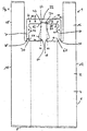
- FIG. 1 shows a plan view of a frontmost on a stack of bags carrying bag 1.
- This bag type is called due to its attachment of the grips 16 and 18 on the bag body 2 and shirt bag carrying bag.
- the bag body 2 comprises a front wall 4 and a rear wall 6 with a closed bottom end 8 and closed sides 12 and 14 which are substantially parallel. Opposite the bottom end 8 is the open mouth end 10 of the bag body 2.
- the opening end 10 is formed by the upper edges of the front wall 4 and rear wall 6.
- the grips 16 and 18 extend away from the bag body 2 and are arranged on the opposite side edges. In the middle between the handles 16 and 18 extends from the opening end 10 of a front strip 20 which is integrally connected to the front wall 4.
- a corresponding rear strip also extends from the rear wall 6 away from the opening end 10 and is preferably the same size and shape as the front strip 20.
- the front strip 20 and the rear strip are immediately adjacent to the opening end 10 an indentation or a narrower section 24 in the direction of the upper end 34 of the front strip 20 widens towards this strip Both sides again first to then uniformly to thin in the direction of the upper end 34. It is advantageous if the width of the upper end 34 of the front strip 20 is selected such that it is greater than the transverse extent of the narrow portion 24.
- the lateral extension points 40 and 42 of the upper portion 34 of the front strip 20 are so far apart that the imaginary lines 44 and 46 emanating from these points parallel to the side walls cut the front strip 20 above the indentation 24, but do not pass through this narrow section 24, but laterally outside of the closest points 48 and 50 of this indentation 24 run. In this way, a tearing of the front wall 4 when removing the front strip 20 can be prevented.
- To the carrying bag 1 further includes a holding device 22.
- This holding device is composed of an upper portion or bracket 32 and at right angles in the direction of the bag body extending portions or connecting arms 28 and 30 together. These lateral sections or side arms are fastened to the front wall 4 and the rear wall 6 (not shown) at a distance from the gripping pieces 16 and 18.
- the weakening line can lie directly in the region of the upper edge course of the opening end 10 (not shown).
- the weakened area or the weakening line between the pocket body and holding device is preferably located at a distance in the direction of the upper web 32 in the side arms 28 and 30 it is already when, as shown, the lines of weakness 36 and 38 are located only slightly above the opening end 10.
- these lines of weakness set at a level at which the narrow portion 24 merges into the widening portion 26.
- the upper portion 34 of the front strip 20 is separably connected to the bracket portion 32 of the holding device 22.
- this separable connection extends across a parting line 54 substantially transverse to the longitudinal axis of the carrier bag and over lateral lines of weakness 80 and 82 extending from the parting line 54 towards the opening end.
- the dividing line 54 can be present both as a separable weakening or perforation line and as an already completely severed line. Especially in the latter case, the upper portions 34 of front and back strips in a stack are mostly cold-blocked for better handling.
- the upper portion 34 of the front strip 20 is in this case slightly inserted into the bracket portion 32 of the holding device 22.
- the weakened areas thus extend over the sections 80, 82 and optionally 54.
- FIG. 2 A second embodiment of the carrying bag according to the invention or the pocket stack according to the invention can be found in FIG. 2 displayed.
- This second embodiment 1 differers from the first embodiment 1, as in FIG. 1 reproduced solely by the fact that the lateral portions 28 'and 30' of the holding device 22 'no longer open into the upper opening end 10 of the bag body 2, but are each separably connected to the front strip 20, in such a way that still always two access openings 68 'and 70' remain, can be guided by the gripping arms of a stand device.
- These lateral portions or side arms 28 'and 30' preferably open in opposite areas of the front strip 20, which adjoin the narrow portion 24.
- the narrow region 24 is preferably arranged directly adjacent to the opening end 10.
- the side arms 28' and 30 'are and the weakening areas 72 and 74 are mounted in a portion of the front strip 20 that is out of the already closed FIG. 1 explanatory imaginary lines 44 and 46.
- the pocket stack according to the invention by way of example on the first embodiment 1 of a carrying bag according to the invention Fig. 1 shown, can be operated in such a way that first of the above-lying carrying bag 1, the front strip 20 in the upper section 34 is removed via the separable portions 80 and 82 and optionally also 54 of the holding device 22.
- the front strip is first to be separated from the rear strip.
- the lines of weakness 36 and 38 next, so that the front wall 4 of the holding device 22 dissolves.
- the corresponding weakening lines between the rear wall 6 and the holding device to solve.
- both the first embodiment and the second embodiment of the carrying bag according to the invention or the bag stack according to the invention are characterized in that there is no connection between the holding or fastening device 22 and the carrying loops or gripping pieces 16 and 18 via a weakened region whose components ,
Landscapes
- Engineering & Computer Science (AREA)
- Mechanical Engineering (AREA)
- Bag Frames (AREA)
- Containers And Packaging Bodies Having A Special Means To Remove Contents (AREA)
- Stackable Containers (AREA)
- Packages (AREA)
Claims (25)
- Sac en matière plastique (1) pour des empilements de sacs, comprenant une paroi antérieure (4) et une paroi postérieure (6), la paroi antérieure et la paroi postérieure définissant un corps de sac (2) ayant une extrémité de fond (8) essentiellement fermée et des côtés (12, 14) au moins partiellement fermés et une extrémité d'ouverture (10) au moins partiellement ouverte faisant face à l'extrémité de fond (8), deux poignées (16, 18) distantes l'une de l'autre et au moins un dispositif de maintien (22) pour le sac (1), la paroi antérieure (4) présentant une bande avant (20), qui s'étend entre les deux poignées (16, 18) en s'éloignant de l'extrémité d'ouverture (10), la paroi postérieure (6) présentant une bande arrière, qui s'étend entre les deux poignées (16, 18) en s'éloignant de l'extrémité d'ouverture (10), et la paroi antérieure (4) et/ou la paroi postérieure (6) étant reliées de manière séparable avec le dispositif de maintien (22) respectivement par-dessus l'extrémité d'ouverture (10) de la paroi antérieure et de la paroi postérieure, se trouvant entre les deux poignées (16, 18) par l'intermédiaire d'au moins un secteur affaibli ou perforé (36, 38), la bande (20) avant et/ou arrière étant reliée(s) de manière séparable avec le dispositif de maintien (22) par l'intermédiaire d'au moins un secteur affaibli ou perforé (54), respectivement par-dessus l'extrémité d'ouverture (10) de paroi antérieure ou de paroi postérieure (4, 6) se trouvant entre les deux poignées (16, 18), caractérisé en ce que
le dispositif de maintien (22) présente au moins deux tronçons de liaison latéraux (28, 30) au corps de sac (2) et un tronçon d'anse (32) reliant ces tronçons de liaison (28, 30), et la bande (20) avant et/ou arrière étant présente(s) entre les deux tronçons de liaison latéraux (28, 30) et étant reliée(s) de manière séparable avec le tronçon d'anse (32). - Sac (1) selon la revendication 1, caractérisé en ce que le dispositif de maintien forme en commun avec la bande (20) avant et/ou arrière et l'extrémité d'ouverture (10) au moins deux ouvertures de maintien (68, 70), en particulier symétriques.
- Sac en matière plastique (1') pour des empilements de sacs, comprenant
une paroi antérieure (4) et une paroi postérieure (6), la paroi antérieure et la paroi postérieure définissant un corps de sac (2) ayant une extrémité de fond (8) essentiellement fermée et des côtés (12, 14) au moins partiellement fermés et une extrémité d'ouverture (10) au moins partiellement ouverte, faisant face à l'extrémité de fond (8), deux poignées (16, 18) distantes l'une de l'autre et au moins un dispositif de maintien (22') pour le sac, la paroi antérieure (4) présentant une bande avant (20), qui s'étend entre les deux poignées (16, 18) en s'éloignant de l'extrémité d'ouverture (10), la paroi postérieure comportant une bande arrière, qui s'étend entre les deux poignées (16, 18) en s'éloignant de l'extrémité d'ouverture (10), et le dispositif de maintien (22') étant relié avec la bande (20) avant et/ou arrière au niveau d'au moins un tronçon de liaison (72, 74) de manière séparable par l'intermédiaire d'au moins un secteur affaibli ou perforé, caractérisé en ce que
le dispositif de maintien (22') forme au moins deux ouvertures de maintien (68', 70') en commun avec la bande (20) avant et/ou arrière, le dispositif de maintien (22') présentant au moins deux tronçons de liaison latéraux (28', 30') au niveau de la bande (20) avant et/ou arrière et un tronçon d'anse (32) reliant ces tronçons de liaison (28', 30'), et la bande (20) avant et/ou arrière étant présente(s) entre les deux tronçons de liaison latéraux (28', 30') et étant reliée(s) de manière séparable avec le tronçon d'anse (32) et le dispositif de maintien (22') présentant avec la bande avant et/ou arrière des tronçons de liaison exclusivement séparables. - Sac (1') selon la revendication 3, caractérisé en ce que
le dispositif de maintien (22') forme au moins deux ouvertures de maintien (68', 70') symétriques en commun avec la bande (20) avant et/ou arrière. - Sac en matière plastique (1') selon la revendication 4, caractérisé en ce que
le dispositif de maintien (22') est relié avec la bande (20) avant et/ou arrière au niveau d'au moins trois tronçons de liaison (72, 74, 54) espacés, par l'intermédiaire de secteurs (72, 74, 54) affaiblis ou perforés. - Sac (1, 1') selon l'une quelconque des revendications précédentes,
caractérisé en ce que
la liaison séparable entre la bande avant (20) et le dispositif de maintien (22, 22') et/ou la bande arrière et le dispositif de maintien (22, 22') et/ou l'extrémité d'ouverture (10) de la paroi antérieure et/ou postérieure (4, 6) avec le dispositif de maintien (22, 22') est réalisée sur au moins une ligne affaiblie ou perforée. - Sac (1, 1') selon l'une quelconque des revendications précédentes,
caractérisé en ce que
la bande (20) avant et/ou arrière est/sont reliée(s) de manière séparable avec le mécanisme de fermeture (22, 22') au niveau du secteur (54) faisant face à l'extrémité d'ouverture (10). - Sac (1, 1') selon l'une quelconque des revendications précédentes,
caractérisé en ce que
au moins un tronçon (24) de bande (20) avant et/ou arrière est dimensionné transversalement à l'axe longitudinal du sac de manière plus étroite qu'un tronçon de bande (20) avant et/ou arrière s'étendant directement ou indirectement dans la direction s'éloignant de l'extrémité d'ouverture (10). - Sac (1, 1') selon la revendication 8, caractérisé en ce que
le tronçon étroit (24) de la bande (20) avant et/ou arrière est voisin de l'extrémité d'ouverture (10). - Sac (1') selon l'une quelconque des revendications 3 à 9, caractérisé en ce que
deux tronçons de liaison (72, 74) du dispositif de maintien (22') avec la bande (20) avant et/ou arrière se trouvent au-dessus du tronçon étroit (24) et le troisième tronçon de liaison (54) est présent au niveau du secteur faisant face à l'extrémité d'ouverture (10) de bande (20) avant et/ou arrière. - Sac (1) selon l'une quelconque des revendications précédentes,
caractérisé en ce que
les secteurs affaiblis ou perforés (36, 38) du dispositif de maintien (22) avec la paroi antérieure et/ou postérieure (4, 6) sont présents dans le secteur de l'extrémité d'ouverture (10). - Sac (1) selon l'une quelconque des revendications 1 à 11, caractérisé en ce que
les secteurs affaiblis ou perforés (36, 38) du dispositif de maintien (22) avec la paroi antérieure et/ou postérieure (4, 6) sont présents à une distance de l'extrémité d'ouverture (10), en particulier dans le dispositif de maintien (22). - Sac (1, 1') selon l'une quelconque des revendications précédentes,
caractérisé en ce que
la bande (20) avant et/ou arrière et/ou le dispositif de maintien (22, 22') sont formés selon une symétrie en miroir. - Sac (1, 1') selon l'une quelconque des revendications précédentes,
caractérisé en ce que
les poignées (16, 18) s'étendent en s'éloignant de l'extrémité d'ouverture (10). - Empilement de sacs, comportant une pluralité de sacs agencés en une pile, selon l'une quelconque des revendications précédentes, la bande arrière d'un sac dans l'empilement étant reliée de manière séparable avec la bande avant du sac suivant dans l'empilement.
- Empilement de sacs selon la revendication 15, caractérisé en ce que
la bande arrière d'un sac dans l'empilement est reliée de manière séparable avec la bande avant du sac suivant dans l'empilement au niveau d'un secteur de liaison bande à bande, en particulier d'un point de liaison bande à bande. - Empilement de sacs selon la revendication 15 ou 16, caractérisé en ce que
le dispositif de maintien et les secteurs affaiblis et perforés sont conçus de manière à ce que, lorsqu'une traction est appliquée à la bande avant pour éloigner de l'empilement le sac positionné en premier, les secteurs affaiblis ou perforés de ce sac cèdent plus tôt que la liaison séparable de la bande arrière de ce sac avec la bande avant du sac suivant. - Empilement de sacs selon l'une quelconque des revendications 15 à 17,
caractérisé en ce que
les bandes avant et arrière sont constituées du même matériau que les parois antérieures et postérieures respectives. - Empilement de sacs selon l'une quelconque des revendications 15 à 18,
caractérisé en ce que
la paroi antérieure et/ou la paroi postérieure d'au moins un sac est/sont réalisée(s) au moins partiellement de manière multicouche. - Empilement de sacs selon l'une quelconque des revendications 15 à 19,
caractérisé en ce que
le dispositif de maintien de l'empilement comporte une pluralité de couches de matériau en feuilles des mécanismes de maintien de paroi antérieure et/ou postérieure. - Empilement de sacs selon l'une quelconque des revendications 15 à 20,
caractérisé en ce que
les mécanismes de maintien de paroi antérieure et/ou postérieure sont verrouillés, en particulier plusieurs fois. - Empilement de sacs selon l'une quelconque des revendications 15 à 21,
caractérisé en ce que
la bande arrière d'un sac est reliée grâce à un adhésif avec la bande avant du sac suivant de l'empilement de sac. - Empilement de sacs selon l'une quelconque des revendications 15 à 22,
caractérisé en ce que
le côté postérieur de la bande arrière et le côté antérieur de la bande avant du sac suivant ont été soumis au moins partiellement à un traitement Corona. - Empilement de sacs selon l'une quelconque des revendications 15 à 23,
caractérisé en ce que
le matériau de la bande arrière est enfoncé dans une bosse rentrante présente dans la bande avant du sac suivant. - Empilement de sacs selon l'une quelconque des revendications 15 à 24,
caractérisé en ce que
les sacs sont fabriqués à partir de polyoléfines comme du polypropylène et du polyéthylène ainsi que de copolymères du polyéthylène et du polypropylène, du polystyrène, des (co)polymères de styrène, en particulier ABS, ASA, SAN, MABS et MBS, de poly(méth)acrylates, de polyesters, en particulier de polybutylènetéréphtalates et de polyéthylènetéréphtalates, de polyuréthannes, d'éthers de polyphénylène, de polycétones, de polyamides, de polyimides, de polychlorures de vinyle, de copolymères éthylène/acétate de vinyle, de polyacrylonitriles, de polycarbonates, de polyoxyméthylènes, de polysulfones, de polyphénylènesulfones ainsi que de mélanges quelconques des matières plastiques ci-dessus.
Priority Applications (4)
| Application Number | Priority Date | Filing Date | Title |
|---|---|---|---|
| EP05027424A EP1803655B1 (fr) | 2005-12-12 | 2005-12-12 | Sac en matière plastique et pile de sacs contenant un tel sac |
| AT05027424T ATE389593T1 (de) | 2005-12-12 | 2005-12-12 | Kunststofftragetasche sowie taschenstapel, enthaltend diese kunststofftragetasche |
| PL05027424T PL1803655T3 (pl) | 2005-12-12 | 2005-12-12 | Torba do noszenia z tworzywa sztucznego oraz pakiet toreb, zawierający taką torbę do noszenia z tworzywa sztucznego |
| DE502005003388T DE502005003388D1 (de) | 2005-12-12 | 2005-12-12 | Kunststofftragetasche sowie Taschenstapel, enthaltend diese Kunststofftragetasche |
Applications Claiming Priority (1)
| Application Number | Priority Date | Filing Date | Title |
|---|---|---|---|
| EP05027424A EP1803655B1 (fr) | 2005-12-12 | 2005-12-12 | Sac en matière plastique et pile de sacs contenant un tel sac |
Publications (2)
| Publication Number | Publication Date |
|---|---|
| EP1803655A1 EP1803655A1 (fr) | 2007-07-04 |
| EP1803655B1 true EP1803655B1 (fr) | 2008-03-19 |
Family
ID=36204388
Family Applications (1)
| Application Number | Title | Priority Date | Filing Date |
|---|---|---|---|
| EP05027424A Expired - Lifetime EP1803655B1 (fr) | 2005-12-12 | 2005-12-12 | Sac en matière plastique et pile de sacs contenant un tel sac |
Country Status (4)
| Country | Link |
|---|---|
| EP (1) | EP1803655B1 (fr) |
| AT (1) | ATE389593T1 (fr) |
| DE (1) | DE502005003388D1 (fr) |
| PL (1) | PL1803655T3 (fr) |
Cited By (1)
| Publication number | Priority date | Publication date | Assignee | Title |
|---|---|---|---|---|
| US9580595B2 (en) | 2012-05-16 | 2017-02-28 | Sabic Global Technologies B.V. | Compositions and articles of manufacture containing branched polycarbonate |
Family Cites Families (8)
| Publication number | Priority date | Publication date | Assignee | Title |
|---|---|---|---|---|
| US4796759A (en) * | 1987-12-29 | 1989-01-10 | C.E.E. Compagnie Europeene Des Emballages | Bundle of supple bags, made of fine material such as plastics material or paper |
| US5333730A (en) * | 1993-03-31 | 1994-08-02 | Mobil Oil Corporation | Bag pack and system for suspending and dispensing bags |
| US5307935A (en) * | 1993-08-23 | 1994-05-03 | Gary Kemanjian | Packs of self opening plastic bags and method of fabricating the same |
| GB2329171B (en) | 1996-01-18 | 1999-05-12 | Cascade Dispensers Ltd | A stack of bags for use with a dispenser |
| CN1149166C (zh) | 2001-06-12 | 2004-05-12 | 覃通衡 | 易取、自开口薄膜提袋的制造方法 |
| GB2391538B (en) | 2002-02-12 | 2004-07-21 | Eps | A stack of bags |
| GB2395938B (en) * | 2002-02-12 | 2004-07-28 | Eps | A stack of bags with interconnecting tabs |
| GB0325563D0 (en) * | 2003-11-01 | 2003-12-03 | 3 S S Ltd | Stacks of bags and dispensers therefor |
-
2005
- 2005-12-12 DE DE502005003388T patent/DE502005003388D1/de not_active Expired - Fee Related
- 2005-12-12 EP EP05027424A patent/EP1803655B1/fr not_active Expired - Lifetime
- 2005-12-12 AT AT05027424T patent/ATE389593T1/de not_active IP Right Cessation
- 2005-12-12 PL PL05027424T patent/PL1803655T3/pl unknown
Cited By (1)
| Publication number | Priority date | Publication date | Assignee | Title |
|---|---|---|---|---|
| US9580595B2 (en) | 2012-05-16 | 2017-02-28 | Sabic Global Technologies B.V. | Compositions and articles of manufacture containing branched polycarbonate |
Also Published As
| Publication number | Publication date |
|---|---|
| PL1803655T3 (pl) | 2008-08-29 |
| EP1803655A1 (fr) | 2007-07-04 |
| DE502005003388D1 (de) | 2008-04-30 |
| ATE389593T1 (de) | 2008-04-15 |
Similar Documents
| Publication | Publication Date | Title |
|---|---|---|
| DE2647830C2 (de) | Lösbares, selbstklebendes Verschlußband | |
| DE4109605A1 (de) | Schlauchbeutelverpackung | |
| DE7934619U1 (de) | Weichpackung aus einer Kunststoffolie, insbesondere für Papiertaschentücher | |
| EP1453735A1 (fr) | Emballage, en particulier boite pliable realisee en carton ou carton lamine | |
| EP2363286B1 (fr) | Feuille d'emballage, emballage et procédé de fabrication pour cet emballage | |
| EP4048606B1 (fr) | Emballage en matériau cellulosique et procédé d'ouverture | |
| DE202009012194U1 (de) | Sicherheitsetikett zum Sichern von in einer Einzelverpackung gehaltenen Medikamenten | |
| DE2909834A1 (de) | Verpackungselement fuer blattgut | |
| EP0226958A2 (fr) | Emballage en forme de cône | |
| WO2009036745A1 (fr) | Feuille en matière synthétique dotée d'une ligne de déchirure et outil pour réaliser cette ligne | |
| EP1803655B1 (fr) | Sac en matière plastique et pile de sacs contenant un tel sac | |
| EP0737157B1 (fr) | Emballage pour pieces de forme allongee | |
| EP0974532A2 (fr) | Distributeur pour bloc de sachets en film de matière thermoplastique | |
| EP3498624B1 (fr) | Sac pour matière en vrac | |
| DE8536241U1 (de) | Verpackung aus flexiblem Material | |
| DE3943064C2 (fr) | ||
| DE60004774T2 (de) | Schachtel mit zwei zu einander versetzten Ausgabeöffnungen | |
| DE2614899A1 (de) | Beutel aus kunststoffolie | |
| DE4344679C2 (de) | Verpackung für stabförmige Teile | |
| DE29509053U1 (de) | Verpackung aus Kunststoff-Folie für Gebrauchsgüter, insbesondere Lebensmittelprodukte in Riegelform | |
| DE9213635U1 (de) | Spender | |
| DE19605503A1 (de) | Klebestreifen zum Verbinden mehrerer Produkte | |
| DE102005019629B4 (de) | Spender-Vorrichtung für doppelseitig klebende Klebestreifen | |
| DE202005002860U1 (de) | Quaderförmige Verpackung | |
| DE69701333T2 (de) | Weichpackung mit Aufhängevorrichtung |
Legal Events
| Date | Code | Title | Description |
|---|---|---|---|
| PUAI | Public reference made under article 153(3) epc to a published international application that has entered the european phase |
Free format text: ORIGINAL CODE: 0009012 |
|
| 17P | Request for examination filed |
Effective date: 20061204 |
|
| AK | Designated contracting states |
Kind code of ref document: A1 Designated state(s): AT BE BG CH CY CZ DE DK EE ES FI FR GB GR HU IE IS IT LI LT LU LV MC NL PL PT RO SE SI SK TR |
|
| AX | Request for extension of the european patent |
Extension state: AL BA HR MK YU |
|
| GRAP | Despatch of communication of intention to grant a patent |
Free format text: ORIGINAL CODE: EPIDOSNIGR1 |
|
| GRAS | Grant fee paid |
Free format text: ORIGINAL CODE: EPIDOSNIGR3 |
|
| GRAA | (expected) grant |
Free format text: ORIGINAL CODE: 0009210 |
|
| AKX | Designation fees paid |
Designated state(s): AT BE BG CH CY CZ DE DK EE ES FI FR GB GR HU IE IS IT LI LT LU LV MC NL PL PT RO SE SI SK TR |
|
| AK | Designated contracting states |
Kind code of ref document: B1 Designated state(s): AT BE BG CH CY CZ DE DK EE ES FI FR GB GR HU IE IS IT LI LT LU LV MC NL PL PT RO SE SI SK TR |
|
| REG | Reference to a national code |
Ref country code: GB Ref legal event code: FG4D Free format text: NOT ENGLISH |
|
| REG | Reference to a national code |
Ref country code: CH Ref legal event code: EP |
|
| REF | Corresponds to: |
Ref document number: 502005003388 Country of ref document: DE Date of ref document: 20080430 Kind code of ref document: P |
|
| REG | Reference to a national code |
Ref country code: IE Ref legal event code: FG4D Free format text: LANGUAGE OF EP DOCUMENT: GERMAN |
|
| PG25 | Lapsed in a contracting state [announced via postgrant information from national office to epo] |
Ref country code: LT Free format text: LAPSE BECAUSE OF FAILURE TO SUBMIT A TRANSLATION OF THE DESCRIPTION OR TO PAY THE FEE WITHIN THE PRESCRIBED TIME-LIMIT Effective date: 20080319 Ref country code: FI Free format text: LAPSE BECAUSE OF FAILURE TO SUBMIT A TRANSLATION OF THE DESCRIPTION OR TO PAY THE FEE WITHIN THE PRESCRIBED TIME-LIMIT Effective date: 20080319 |
|
| REG | Reference to a national code |
Ref country code: PL Ref legal event code: T3 |
|
| NLV1 | Nl: lapsed or annulled due to failure to fulfill the requirements of art. 29p and 29m of the patents act | ||
| PG25 | Lapsed in a contracting state [announced via postgrant information from national office to epo] |
Ref country code: SI Free format text: LAPSE BECAUSE OF FAILURE TO SUBMIT A TRANSLATION OF THE DESCRIPTION OR TO PAY THE FEE WITHIN THE PRESCRIBED TIME-LIMIT Effective date: 20080319 Ref country code: LV Free format text: LAPSE BECAUSE OF FAILURE TO SUBMIT A TRANSLATION OF THE DESCRIPTION OR TO PAY THE FEE WITHIN THE PRESCRIBED TIME-LIMIT Effective date: 20080319 |
|
| REG | Reference to a national code |
Ref country code: IE Ref legal event code: FD4D |
|
| PG25 | Lapsed in a contracting state [announced via postgrant information from national office to epo] |
Ref country code: SK Free format text: LAPSE BECAUSE OF FAILURE TO SUBMIT A TRANSLATION OF THE DESCRIPTION OR TO PAY THE FEE WITHIN THE PRESCRIBED TIME-LIMIT Effective date: 20080319 Ref country code: SE Free format text: LAPSE BECAUSE OF FAILURE TO SUBMIT A TRANSLATION OF THE DESCRIPTION OR TO PAY THE FEE WITHIN THE PRESCRIBED TIME-LIMIT Effective date: 20080619 Ref country code: PT Free format text: LAPSE BECAUSE OF FAILURE TO SUBMIT A TRANSLATION OF THE DESCRIPTION OR TO PAY THE FEE WITHIN THE PRESCRIBED TIME-LIMIT Effective date: 20080827 Ref country code: ES Free format text: LAPSE BECAUSE OF FAILURE TO SUBMIT A TRANSLATION OF THE DESCRIPTION OR TO PAY THE FEE WITHIN THE PRESCRIBED TIME-LIMIT Effective date: 20080630 |
|
| PG25 | Lapsed in a contracting state [announced via postgrant information from national office to epo] |
Ref country code: NL Free format text: LAPSE BECAUSE OF FAILURE TO SUBMIT A TRANSLATION OF THE DESCRIPTION OR TO PAY THE FEE WITHIN THE PRESCRIBED TIME-LIMIT Effective date: 20080319 Ref country code: RO Free format text: LAPSE BECAUSE OF FAILURE TO SUBMIT A TRANSLATION OF THE DESCRIPTION OR TO PAY THE FEE WITHIN THE PRESCRIBED TIME-LIMIT Effective date: 20080319 |
|
| PG25 | Lapsed in a contracting state [announced via postgrant information from national office to epo] |
Ref country code: IS Free format text: LAPSE BECAUSE OF FAILURE TO SUBMIT A TRANSLATION OF THE DESCRIPTION OR TO PAY THE FEE WITHIN THE PRESCRIBED TIME-LIMIT Effective date: 20080719 |
|
| EN | Fr: translation not filed | ||
| PLBE | No opposition filed within time limit |
Free format text: ORIGINAL CODE: 0009261 |
|
| STAA | Information on the status of an ep patent application or granted ep patent |
Free format text: STATUS: NO OPPOSITION FILED WITHIN TIME LIMIT |
|
| PG25 | Lapsed in a contracting state [announced via postgrant information from national office to epo] |
Ref country code: IE Free format text: LAPSE BECAUSE OF FAILURE TO SUBMIT A TRANSLATION OF THE DESCRIPTION OR TO PAY THE FEE WITHIN THE PRESCRIBED TIME-LIMIT Effective date: 20080319 Ref country code: DK Free format text: LAPSE BECAUSE OF FAILURE TO SUBMIT A TRANSLATION OF THE DESCRIPTION OR TO PAY THE FEE WITHIN THE PRESCRIBED TIME-LIMIT Effective date: 20080319 |
|
| PGFP | Annual fee paid to national office [announced via postgrant information from national office to epo] |
Ref country code: CZ Payment date: 20081201 Year of fee payment: 4 |
|
| 26N | No opposition filed |
Effective date: 20081222 |
|
| PGFP | Annual fee paid to national office [announced via postgrant information from national office to epo] |
Ref country code: PL Payment date: 20081202 Year of fee payment: 4 |
|
| PG25 | Lapsed in a contracting state [announced via postgrant information from national office to epo] |
Ref country code: FR Free format text: LAPSE BECAUSE OF FAILURE TO SUBMIT A TRANSLATION OF THE DESCRIPTION OR TO PAY THE FEE WITHIN THE PRESCRIBED TIME-LIMIT Effective date: 20090109 Ref country code: EE Free format text: LAPSE BECAUSE OF FAILURE TO SUBMIT A TRANSLATION OF THE DESCRIPTION OR TO PAY THE FEE WITHIN THE PRESCRIBED TIME-LIMIT Effective date: 20080319 Ref country code: BG Free format text: LAPSE BECAUSE OF FAILURE TO SUBMIT A TRANSLATION OF THE DESCRIPTION OR TO PAY THE FEE WITHIN THE PRESCRIBED TIME-LIMIT Effective date: 20080619 |
|
| PGFP | Annual fee paid to national office [announced via postgrant information from national office to epo] |
Ref country code: DE Payment date: 20081222 Year of fee payment: 4 |
|
| BERE | Be: lapsed |
Owner name: PAPIER-METTLER - INH. MICHAEL METTLER Effective date: 20081231 |
|
| PG25 | Lapsed in a contracting state [announced via postgrant information from national office to epo] |
Ref country code: MC Free format text: LAPSE BECAUSE OF NON-PAYMENT OF DUE FEES Effective date: 20081231 |
|
| PG25 | Lapsed in a contracting state [announced via postgrant information from national office to epo] |
Ref country code: IT Free format text: LAPSE BECAUSE OF FAILURE TO SUBMIT A TRANSLATION OF THE DESCRIPTION OR TO PAY THE FEE WITHIN THE PRESCRIBED TIME-LIMIT Effective date: 20080319 |
|
| PG25 | Lapsed in a contracting state [announced via postgrant information from national office to epo] |
Ref country code: CY Free format text: LAPSE BECAUSE OF FAILURE TO SUBMIT A TRANSLATION OF THE DESCRIPTION OR TO PAY THE FEE WITHIN THE PRESCRIBED TIME-LIMIT Effective date: 20080319 Ref country code: BE Free format text: LAPSE BECAUSE OF NON-PAYMENT OF DUE FEES Effective date: 20081231 |
|
| PG25 | Lapsed in a contracting state [announced via postgrant information from national office to epo] |
Ref country code: AT Free format text: LAPSE BECAUSE OF NON-PAYMENT OF DUE FEES Effective date: 20081212 |
|
| PG25 | Lapsed in a contracting state [announced via postgrant information from national office to epo] |
Ref country code: HU Free format text: LAPSE BECAUSE OF FAILURE TO SUBMIT A TRANSLATION OF THE DESCRIPTION OR TO PAY THE FEE WITHIN THE PRESCRIBED TIME-LIMIT Effective date: 20080920 Ref country code: LU Free format text: LAPSE BECAUSE OF NON-PAYMENT OF DUE FEES Effective date: 20081212 |
|
| REG | Reference to a national code |
Ref country code: CH Ref legal event code: PL |
|
| GBPC | Gb: european patent ceased through non-payment of renewal fee |
Effective date: 20091212 |
|
| PG25 | Lapsed in a contracting state [announced via postgrant information from national office to epo] |
Ref country code: CZ Free format text: LAPSE BECAUSE OF NON-PAYMENT OF DUE FEES Effective date: 20091212 Ref country code: TR Free format text: LAPSE BECAUSE OF FAILURE TO SUBMIT A TRANSLATION OF THE DESCRIPTION OR TO PAY THE FEE WITHIN THE PRESCRIBED TIME-LIMIT Effective date: 20080319 |
|
| PG25 | Lapsed in a contracting state [announced via postgrant information from national office to epo] |
Ref country code: GR Free format text: LAPSE BECAUSE OF FAILURE TO SUBMIT A TRANSLATION OF THE DESCRIPTION OR TO PAY THE FEE WITHIN THE PRESCRIBED TIME-LIMIT Effective date: 20080620 Ref country code: LI Free format text: LAPSE BECAUSE OF NON-PAYMENT OF DUE FEES Effective date: 20091231 Ref country code: CH Free format text: LAPSE BECAUSE OF NON-PAYMENT OF DUE FEES Effective date: 20091231 |
|
| PG25 | Lapsed in a contracting state [announced via postgrant information from national office to epo] |
Ref country code: DE Free format text: LAPSE BECAUSE OF NON-PAYMENT OF DUE FEES Effective date: 20100701 |
|
| PG25 | Lapsed in a contracting state [announced via postgrant information from national office to epo] |
Ref country code: GB Free format text: LAPSE BECAUSE OF NON-PAYMENT OF DUE FEES Effective date: 20091212 |
|
| PG25 | Lapsed in a contracting state [announced via postgrant information from national office to epo] |
Ref country code: PL Free format text: LAPSE BECAUSE OF NON-PAYMENT OF DUE FEES Effective date: 20091212 |
|
| REG | Reference to a national code |
Ref country code: PL Ref legal event code: LAPE |
|
| P01 | Opt-out of the competence of the unified patent court (upc) registered |
Effective date: 20230331 |