EP1803855A2 - Drehbarer Oberwagen eines Baggers mit minimiertem Hecküberstand - Google Patents
Drehbarer Oberwagen eines Baggers mit minimiertem Hecküberstand Download PDFInfo
- Publication number
- EP1803855A2 EP1803855A2 EP06127107A EP06127107A EP1803855A2 EP 1803855 A2 EP1803855 A2 EP 1803855A2 EP 06127107 A EP06127107 A EP 06127107A EP 06127107 A EP06127107 A EP 06127107A EP 1803855 A2 EP1803855 A2 EP 1803855A2
- Authority
- EP
- European Patent Office
- Prior art keywords
- swing body
- upper swing
- engine
- engine room
- support
- Prior art date
- Legal status (The legal status is an assumption and is not a legal conclusion. Google has not performed a legal analysis and makes no representation as to the accuracy of the status listed.)
- Withdrawn
Links
Images


Classifications
-
- E—FIXED CONSTRUCTIONS
- E02—HYDRAULIC ENGINEERING; FOUNDATIONS; SOIL SHIFTING
- E02F—DREDGING; SOIL-SHIFTING
- E02F9/00—Component parts of dredgers or soil-shifting machines, not restricted to one of the kinds covered by groups E02F3/00 - E02F7/00
-
- E—FIXED CONSTRUCTIONS
- E02—HYDRAULIC ENGINEERING; FOUNDATIONS; SOIL SHIFTING
- E02F—DREDGING; SOIL-SHIFTING
- E02F3/00—Dredgers; Soil-shifting machines
- E02F3/04—Dredgers; Soil-shifting machines mechanically-driven
- E02F3/28—Dredgers; Soil-shifting machines mechanically-driven with digging tools mounted on a dipper- or bucket-arm, i.e. there is either one arm or a pair of arms, e.g. dippers, buckets
- E02F3/30—Dredgers; Soil-shifting machines mechanically-driven with digging tools mounted on a dipper- or bucket-arm, i.e. there is either one arm or a pair of arms, e.g. dippers, buckets with a dipper-arm pivoted on a cantilever beam, i.e. boom
- E02F3/32—Dredgers; Soil-shifting machines mechanically-driven with digging tools mounted on a dipper- or bucket-arm, i.e. there is either one arm or a pair of arms, e.g. dippers, buckets with a dipper-arm pivoted on a cantilever beam, i.e. boom working downwardly and towards the machine, e.g. with backhoes
- E02F3/325—Backhoes of the miniature type
-
- B—PERFORMING OPERATIONS; TRANSPORTING
- B60—VEHICLES IN GENERAL
- B60K—ARRANGEMENT OR MOUNTING OF PROPULSION UNITS OR OF TRANSMISSIONS IN VEHICLES; ARRANGEMENT OR MOUNTING OF PLURAL DIVERSE PRIME-MOVERS IN VEHICLES; AUXILIARY DRIVES FOR VEHICLES; INSTRUMENTATION OR DASHBOARDS FOR VEHICLES; ARRANGEMENTS IN CONNECTION WITH COOLING, AIR INTAKE, GAS EXHAUST OR FUEL SUPPLY OF PROPULSION UNITS IN VEHICLES
- B60K11/00—Arrangement in connection with cooling of propulsion units
- B60K11/02—Arrangement in connection with cooling of propulsion units with liquid cooling
- B60K11/04—Arrangement or mounting of radiators, radiator shutters, or radiator blinds
-
- E—FIXED CONSTRUCTIONS
- E02—HYDRAULIC ENGINEERING; FOUNDATIONS; SOIL SHIFTING
- E02F—DREDGING; SOIL-SHIFTING
- E02F9/00—Component parts of dredgers or soil-shifting machines, not restricted to one of the kinds covered by groups E02F3/00 - E02F7/00
- E02F9/08—Superstructures; Supports for superstructures
- E02F9/0858—Arrangement of component parts installed on superstructures not otherwise provided for, e.g. electric components, fenders, air-conditioning units
- E02F9/0866—Engine compartment, e.g. heat exchangers, exhaust filters, cooling devices, silencers, mufflers, position of hydraulic pumps in the engine compartment
Definitions
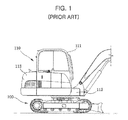
- the operating apparatus in order to smoothly perform the tasks of excavating earth/sand or aggregate, loading earth/sand or aggregate on a vehicle, or compacting the ground, the operating apparatus should be located at a foremost portion of the upper swing body (110). Further, it is preferred that the cab (111) in which an operator sits and manipulates the operating apparatus be disposed at a front side of the upper swing body (110) to secure a front visual field of the operator. Accordingly, the engine room is inevitably disposed at a side or rear of the cab (111) in the upper swing body (110). Considering the balance of a weight distribution, the occurrence of operation noise/vibration and easy access for maintenance, however, it is desirable to arrange the engine room at the rear of the cab (111).
- the engine room cover may include a first cover pivotable to open and close a rear portion of the engine room, and a second cover pivotable to open and close a lateral side portion of the engine room, the first cover may be hingedly supported by a hinge portion provided at the horizontal frame, and the second cover may be selectively locked by a locking member provided at either of the pair of vertical frames.
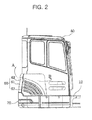
- the cab (80) is a box-shaped structure formed with an inner space, so that an operator can get in the cab and operate the excavator.
- the cab (80) has a front lower portion that is in direct contact with and supported by the main frame (12), and a rear lower portion that is not in direct contact with but spaced apart from the main frame (12). That is, a certain space is defined between the rear lower portion of the cab (80) and the main frame (12).
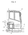
- the upper swing body of an excavator comprises the main frame (12) on which the engine (10) is mounted; a cooling fan (14) provided at a right side of the engine (10); the support (16) provided on the main frame (12); the radiator (20) provided on the support (16) to face the cooling fan (14); the oil cooler (30) provided on the support (16) to face the radiator (20); and a vortex prevention plate (40) provided above the radiator (20) and the oil cooler (30).
- the main frame (12) is to constitute the skeleton of the excavator and supports the various components described above.
- the counterweight (70) is supported by a rear portion of the main frame (12), and the operating apparatus (not shown) is installed at a front portion of the main frame.
- the support (16) comprises the left and right vertical frames (17, 18) provided at the rear portion of the main frame (12) such that the vertical frames (17, 18) are laterally spaced apart by a certain distance from each other, and the horizontal frame (19) connecting the upper ends of the left and right vertical frames (17, 18).
- the radiator (20) and the oil cooler (30) upon demounting of parts associated with the engine, the radiator (20) and the oil cooler (30). That is, since the support (16) has only the frames (17, 18, 19) each of which is in the form of a beam or square bar, it is easy to replace the radiator (20) and the oil cooler (30) with new ones.
- the radiator (20) is installed on the main frame (12) to face the cooling fan (14). More specifically, an upper end of the radiator (20) is fixed to a first fixing bracket (22), which is installed on the right vertical frame 18, by means of bolts, and a lower end of the radiator (20) is simply placed on and supported by a mounting plate (24), which is provided on the main frame (12), without coupling using a bolt. A mounting rubber (25) is provided on the mounting plate (24) and prevents from transmitting vibration of the main frame (12) to the radiator.
- a passage (P) through which various wires and hydraulic lines connected to the engine (10) pass is formed between a lower portion of the mounting plate (24) and the main frame (12).
- the various wires and hydraulic lines (L) are routed on another bypass path.
- a passage (P) through which various wires and hydraulic lines (L) can pass be provided even in a narrow space by installing the radiator (20) to be spaced apart by a certain distance from the main frame (12).
- the vortex prevention plate (40) has one end fixed to the first fixing bracket (22) so as to cover the radiator (20) and the oil cooler (30) thereabove and the other end extending horizontally to the right side. A front end of the vortex prevention plate (40) is fixed to the oil tank (50).
- the vortex prevention plate (40) prevents the introduced external air from flowing into any space above the radiator (20) and the oil cooler (30) and generating a vortex, and guides the external air to the radiator (20) and the oil cooler (30), resulting in improved cooling efficiency.
- a sound absorbing plate (41) made of a sound absorbing material such as sponge be attached to a lower surface of the vortex prevention plate (40).
- the second locking member (65) comprises a pair of fixing bolts (not shown) fastened to fastening holes (66) provided in the second locking member (65). Accordingly, the support (16) can perform the functions of supporting the cab (80) and the first cover (61) and fixing the second cover (62).
- the support is configured not to cover the radiator and the oil cooler so that the radiator and the oil cooler can be easily replaced with new ones.
- the replacement of the radiator and the oil cooler can be more facilitated. Since the radiator and the oil cooler can be easily replaced as above, the serviceability of the excavator is improved.
Landscapes
- Engineering & Computer Science (AREA)
- Mining & Mineral Resources (AREA)
- Civil Engineering (AREA)
- General Engineering & Computer Science (AREA)
- Structural Engineering (AREA)
- Mechanical Engineering (AREA)
- Chemical & Material Sciences (AREA)
- Combustion & Propulsion (AREA)
- Transportation (AREA)
- Component Parts Of Construction Machinery (AREA)
- Cooling, Air Intake And Gas Exhaust, And Fuel Tank Arrangements In Propulsion Units (AREA)
Applications Claiming Priority (1)
| Application Number | Priority Date | Filing Date | Title |
|---|---|---|---|
| KR1020050130228A KR100656068B1 (ko) | 2005-12-27 | 2005-12-27 | 굴삭기의 냉각장치 |
Publications (2)
| Publication Number | Publication Date |
|---|---|
| EP1803855A2 true EP1803855A2 (de) | 2007-07-04 |
| EP1803855A3 EP1803855A3 (de) | 2007-09-05 |
Family
ID=37732818
Family Applications (1)
| Application Number | Title | Priority Date | Filing Date |
|---|---|---|---|
| EP06127107A Withdrawn EP1803855A3 (de) | 2005-12-27 | 2006-12-22 | Drehbarer Oberwagen eines Baggers mit minimiertem Hecküberstand |
Country Status (4)
| Country | Link |
|---|---|
| US (1) | US7661497B2 (de) |
| EP (1) | EP1803855A3 (de) |
| KR (1) | KR100656068B1 (de) |
| CN (1) | CN1990963B (de) |
Families Citing this family (11)
| Publication number | Priority date | Publication date | Assignee | Title |
|---|---|---|---|---|
| JP4707566B2 (ja) * | 2006-01-13 | 2011-06-22 | 日立建機株式会社 | 建設機械の遮熱構造 |
| JP2013087455A (ja) * | 2011-10-14 | 2013-05-13 | Kobelco Contstruction Machinery Ltd | 作業機械 |
| CN102839706B (zh) * | 2012-09-27 | 2014-07-16 | 太原重工股份有限公司 | 一种大型矿用液压挖掘机上部平台 |
| JP6546056B2 (ja) * | 2015-09-28 | 2019-07-17 | 株式会社日立建機ティエラ | 小型油圧ショベル |
| US11413955B2 (en) * | 2018-06-29 | 2022-08-16 | Kubota Corporation | Working machine |
| JP7101632B2 (ja) * | 2019-03-26 | 2022-07-15 | 株式会社クボタ | 作業車 |
| JP7507664B2 (ja) * | 2020-11-18 | 2024-06-28 | 日立建機株式会社 | 建設機械 |
| JP7530819B2 (ja) * | 2020-12-22 | 2024-08-08 | ヤンマーホールディングス株式会社 | 建設機械 |
| JP2022098754A (ja) * | 2020-12-22 | 2022-07-04 | ヤンマーホールディングス株式会社 | 建設機械 |
| JP7562471B2 (ja) * | 2021-04-27 | 2024-10-07 | 日本車輌製造株式会社 | 建設機械 |
| JP7790881B2 (ja) * | 2021-06-30 | 2025-12-23 | 住友建機株式会社 | ショベル |
Family Cites Families (16)
| Publication number | Priority date | Publication date | Assignee | Title |
|---|---|---|---|---|
| JPH06144022A (ja) | 1992-11-06 | 1994-05-24 | Yanmar Diesel Engine Co Ltd | 走行作業車の防音装置 |
| JP2945576B2 (ja) | 1994-01-17 | 1999-09-06 | 株式会社クボタ | バックホウのボンネット構造 |
| JP3386652B2 (ja) * | 1995-04-04 | 2003-03-17 | 株式会社クボタ | 建設機械のラジエータ装置 |
| JP3115791B2 (ja) * | 1995-05-10 | 2000-12-11 | 株式会社クボタ | 旋回作業機の上部構造 |
| JP3294100B2 (ja) | 1996-03-29 | 2002-06-17 | 株式会社クボタ | バックホウ |
| US6170588B1 (en) * | 1997-06-03 | 2001-01-09 | Hitachi Construction Machinery Co., Ltd. | Revolving construction machine |
| DE19839783B4 (de) * | 1997-09-04 | 2006-04-06 | Kubota Corp. | Steuerventilmechanismus für ein Arbeitsfahrzeug mit drehbarem Aufbau |
| US6688424B1 (en) * | 1997-10-24 | 2004-02-10 | Komatsu Ltd. | Noise absorbing device and device for taking air into engine room of a construction machine |
| JP2000062474A (ja) * | 1998-08-21 | 2000-02-29 | Komatsu Ltd | 作業車両の冷却装置 |
| US6431299B1 (en) * | 2000-04-05 | 2002-08-13 | Clark Equipment Company | Cooling air ducting for excavator |
| JP3691767B2 (ja) * | 2001-06-14 | 2005-09-07 | 株式会社クボタ | 旋回作業機のボンネット支持構造 |
| JP3903136B2 (ja) * | 2001-11-05 | 2007-04-11 | 株式会社小松製作所 | 建設機械の冷却装置 |
| JP2004058796A (ja) | 2002-07-26 | 2004-02-26 | Hitachi Constr Mach Co Ltd | 建設機械 |
| WO2005035341A1 (ja) * | 2003-10-14 | 2005-04-21 | Hitachi Construction Machinery Co., Ltd. | 建設機械 |
| US7204329B2 (en) * | 2004-03-24 | 2007-04-17 | Deere & Company | Under-hood engine air intake system |
| CN100482901C (zh) * | 2004-03-29 | 2009-04-29 | 株式会社久保田 | 具有旋转台的旋转作业机 |
-
2005
- 2005-12-27 KR KR1020050130228A patent/KR100656068B1/ko not_active Expired - Fee Related
-
2006
- 2006-12-22 EP EP06127107A patent/EP1803855A3/de not_active Withdrawn
- 2006-12-22 CN CN2006101700232A patent/CN1990963B/zh not_active Expired - Fee Related
- 2006-12-22 US US11/615,385 patent/US7661497B2/en not_active Expired - Fee Related
Also Published As
| Publication number | Publication date |
|---|---|
| CN1990963B (zh) | 2011-09-14 |
| US20070163826A1 (en) | 2007-07-19 |
| EP1803855A3 (de) | 2007-09-05 |
| CN1990963A (zh) | 2007-07-04 |
| KR100656068B1 (ko) | 2006-12-11 |
| US7661497B2 (en) | 2010-02-16 |
Similar Documents
| Publication | Publication Date | Title |
|---|---|---|
| US7188865B2 (en) | Counterweight for hydraulic shovel | |
| EP2248695B1 (de) | Baumaschine | |
| CN101688383B (zh) | 工程机械 | |
| JP4153521B2 (ja) | 建設機械 | |
| US7661497B2 (en) | Upper swing body with minimized rear protrusion in excavator | |
| KR101350254B1 (ko) | 유압 셔블 | |
| US8397851B2 (en) | Swiveling work machine | |
| JP4953191B2 (ja) | 建設機械 | |
| KR101059337B1 (ko) | 건설 기계 | |
| EP2647771B1 (de) | Baumaschine | |
| US20110017537A1 (en) | Working Vehicle | |
| JP4075661B2 (ja) | 作業機械 | |
| EP1306490B1 (de) | Drehbare maschine | |
| CN114502404A (zh) | 用于建筑机械冷却风扇的布置结构 | |
| WO2014088033A1 (ja) | 建設機械 | |
| JP4440730B2 (ja) | 建設機械 | |
| JPH10140613A (ja) | 建設機械 | |
| JP6961635B2 (ja) | 建設機械 | |
| JP3429622B2 (ja) | 建設機械の上部旋回体 | |
| JP4451709B2 (ja) | 作業機械のエンジンフード取付構造 | |
| WO2025192207A1 (ja) | 電動式建設機械 | |
| KR19990062547A (ko) | 백호 | |
| JP4535088B2 (ja) | 作業機械 | |
| JP2023150759A (ja) | 旋回作業機 | |
| JP2023150760A (ja) | 旋回作業機 |
Legal Events
| Date | Code | Title | Description |
|---|---|---|---|
| PUAI | Public reference made under article 153(3) epc to a published international application that has entered the european phase |
Free format text: ORIGINAL CODE: 0009012 |
|
| AK | Designated contracting states |
Kind code of ref document: A2 Designated state(s): AT BE BG CH CY CZ DE DK EE ES FI FR GB GR HU IE IS IT LI LT LU LV MC NL PL PT RO SE SI SK TR |
|
| AX | Request for extension of the european patent |
Extension state: AL BA HR MK YU |
|
| PUAL | Search report despatched |
Free format text: ORIGINAL CODE: 0009013 |
|
| AK | Designated contracting states |
Kind code of ref document: A3 Designated state(s): AT BE BG CH CY CZ DE DK EE ES FI FR GB GR HU IE IS IT LI LT LU LV MC NL PL PT RO SE SI SK TR |
|
| AX | Request for extension of the european patent |
Extension state: AL BA HR MK YU |
|
| 17P | Request for examination filed |
Effective date: 20080305 |
|
| 17Q | First examination report despatched |
Effective date: 20080410 |
|
| AKX | Designation fees paid |
Designated state(s): DE FR GB IT |
|
| STAA | Information on the status of an ep patent application or granted ep patent |
Free format text: STATUS: THE APPLICATION IS DEEMED TO BE WITHDRAWN |
|
| 18D | Application deemed to be withdrawn |
Effective date: 20081021 |