EP1803902A1 - Dispositif de support pour un anneau de réglage enveloppant un support d'aubes circulaire espacé - Google Patents
Dispositif de support pour un anneau de réglage enveloppant un support d'aubes circulaire espacé Download PDFInfo
- Publication number
- EP1803902A1 EP1803902A1 EP06000027A EP06000027A EP1803902A1 EP 1803902 A1 EP1803902 A1 EP 1803902A1 EP 06000027 A EP06000027 A EP 06000027A EP 06000027 A EP06000027 A EP 06000027A EP 1803902 A1 EP1803902 A1 EP 1803902A1
- Authority
- EP
- European Patent Office
- Prior art keywords
- adjusting ring
- blade carrier
- lever
- blades
- roller
- Prior art date
- Legal status (The legal status is an assumption and is not a legal conclusion. Google has not performed a legal analysis and makes no representation as to the accuracy of the status listed.)
- Granted
Links
- 238000002485 combustion reaction Methods 0.000 description 4
- 238000006243 chemical reaction Methods 0.000 description 3
- 238000006073 displacement reaction Methods 0.000 description 3
- 230000000712 assembly Effects 0.000 description 2
- 238000000429 assembly Methods 0.000 description 2
- 239000012080 ambient air Substances 0.000 description 1
- 238000005452 bending Methods 0.000 description 1
- 230000005284 excitation Effects 0.000 description 1
- 230000014759 maintenance of location Effects 0.000 description 1
- 238000004519 manufacturing process Methods 0.000 description 1
- 239000000463 material Substances 0.000 description 1
- 230000036316 preload Effects 0.000 description 1
- 230000000630 rising effect Effects 0.000 description 1
Images
Classifications
-
- F—MECHANICAL ENGINEERING; LIGHTING; HEATING; WEAPONS; BLASTING
- F04—POSITIVE - DISPLACEMENT MACHINES FOR LIQUIDS; PUMPS FOR LIQUIDS OR ELASTIC FLUIDS
- F04D—NON-POSITIVE-DISPLACEMENT PUMPS
- F04D29/00—Details, component parts, or accessories
- F04D29/40—Casings; Connections of working fluid
- F04D29/52—Casings; Connections of working fluid for axial pumps
- F04D29/54—Fluid-guiding means, e.g. diffusers
- F04D29/56—Fluid-guiding means, e.g. diffusers adjustable
- F04D29/563—Fluid-guiding means, e.g. diffusers adjustable specially adapted for elastic fluid pumps
-
- F—MECHANICAL ENGINEERING; LIGHTING; HEATING; WEAPONS; BLASTING
- F01—MACHINES OR ENGINES IN GENERAL; ENGINE PLANTS IN GENERAL; STEAM ENGINES
- F01D—NON-POSITIVE DISPLACEMENT MACHINES OR ENGINES, e.g. STEAM TURBINES
- F01D17/00—Regulating or controlling by varying flow
- F01D17/10—Final actuators
- F01D17/12—Final actuators arranged in stator parts
- F01D17/14—Final actuators arranged in stator parts varying effective cross-sectional area of nozzles or guide conduits
- F01D17/16—Final actuators arranged in stator parts varying effective cross-sectional area of nozzles or guide conduits by means of nozzle vanes
- F01D17/162—Final actuators arranged in stator parts varying effective cross-sectional area of nozzles or guide conduits by means of nozzle vanes for axial flow, i.e. the vanes turning around axes which are essentially perpendicular to the rotor centre line
-
- F—MECHANICAL ENGINEERING; LIGHTING; HEATING; WEAPONS; BLASTING
- F05—INDEXING SCHEMES RELATING TO ENGINES OR PUMPS IN VARIOUS SUBCLASSES OF CLASSES F01-F04
- F05D—INDEXING SCHEME FOR ASPECTS RELATING TO NON-POSITIVE-DISPLACEMENT MACHINES OR ENGINES, GAS-TURBINES OR JET-PROPULSION PLANTS
- F05D2260/00—Function
- F05D2260/50—Kinematic linkage, i.e. transmission of position
Definitions
- the invention relates to a device for supporting a substantially annular blade carrier encompassing encompassing adjusting ring, which is rotatable about an identical with the blade carrier central axis in the circumferential direction to adjust radially extending vanes of a ring of a turbomachine.
- a device of such type is for example from the US 5,549,448 out.
- a collar concentric with the center axis of the compressor surrounds its inner casing.
- Each about its longitudinal axis rotatable vane of the vane ring is connected in each case via a pivot lever with the adjusting ring, which is rotatable in the circumferential direction.
- the rotation of the adjusting ring in the circumferential direction causes via the pivot lever, a rotation of the guide vanes about the respective longitudinal axis.
- the adjusting ring is moved by a drive device in the circumferential direction, which simultaneously supports the adjusting ring.
- the disk spring assemblies allow the adjusting ring to move in the axial direction.
- this leads to flow losses in the compressor due to the circumferentially asymmetrically or differently adjusted guide vanes of the rim and, on the other hand, to wear on the support of the adjusting ring and on the latter itself.
- the object of the present invention is to provide a wear-resistant and reliable device for supporting a substantially circular blade carrier spaced encompassing adjusting ring for adjusting the radially extending, rotatable about its longitudinal axis blades of a ring.
- the device provides between the blade carrier and the adjusting ring, distributed over the circumference, each tangentially extending, one-armed lever, each having at their free ends a rotatable roller, which are unrolled on the adjusting ring or on the blade carrier in the circumferential direction.
- the one-armed lever which are elastic in the radial direction, the previously possible in the axial direction of mobility of the adjusting ring is suppressed because the one-sided firmly clamped lever in the axial direction has a particularly high rigidity. Due to the particularly high axial rigidity, the levers can be absorbed and compensated for the axial forces arising from the reaction forces of the adjustable vanes without additional structural elements, such as disc springs, receptacles or guide elements.
- a support for the adjusting ring can be specified, which only allows a direction of rotation in the circumferential direction of the adjusting ring and suppresses a tilting or a partial displacement in the axial direction.
- the wear on the adjusting ring, on the attachment of the one-armed lever and on the rotatable rollers, which are unrolled in the circumferential direction on the adjusting ring or on the blade carrier avoided.
- a steadily symmetrical adjustment of the blades of a ring of a turbomachine is ensured, so that no losses in the blades of the ring of the turbomachine flowing around medium occur.
- the efficiency of the turbomachine is permanently maintained.
- each lever The role facing away from the first end of each lever is firmly clamped, for example, on the blade carrier and the rotatably mounted on him roller is unrolled on the inside of the adjusting ring.
- the lever can then be designed simply as a cross-sectionally rectangular strut or bending beam.
- the rotatably mounted roller is provided, which in this case is provided on the inside of the adjusting ring, i. can be unrolled on the inner circumferential surface.
- each roller is rotatable about a roller axis parallel to the central axis. This allows the use of cylindrical surfaces on the collar or on the blade carrier, where also cylindrical rollers are unrolled.
- each lever is bolted to the blade carrier, so that a particularly simple assembly and disassembly of the lever or the lever on the blade carrier is possible.
- each lever has at least one elongated hole extending in the tangential direction for receiving the screw connection.
- an endlessly circumferential annular groove is provided with a groove base on the inside of the adjusting ring, on which the rollers are unrolled.
- the groove walls of the annular groove guide the rollers and thus prevent the slipping of the rollers of the tread.
- the device for supporting an adjusting ring in a turbomachine for example in an optionally multi-stage axial compressor used, the drive for adjusting the blades has a blade carrier encompassing adjusting ring which is supported according to one of claims 1 to 7.
- the blades may be formed as guide vanes or as adjustable inlet blades of a compressor.
- the invention could be applied to a steam turbine having variable inlet or stator vanes.
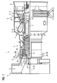
- FIG. 1 shows a gas turbine 1 in a longitudinal partial section. It has inside a rotatably mounted about a rotation axis 2 rotor 3, which is also referred to as a turbine runner. Along the rotor 3 successive an intake 4, a compressor 5, a toroidal annular combustion chamber 6 with a plurality of rotationally symmetrical to each other arranged burners 7, a turbine unit 8 and an exhaust housing 9.
- the annular combustion chamber 6 forms a combustion chamber 17, which communicates with an annular hot gas channel 18.
- There four successive turbine stages 10 form the turbine unit 8.
- Each turbine stage 10 is formed of two blade rings. As seen in the flow direction of a hot gas 11 produced in the annular combustion chamber 6, in the hot gas channel 18 in each case one row of guide blades 13 formed by a blade 15 series 14.
- the vanes 12 are attached to the stator, whereas the blades 15 a row 14 mounted by means of a turbine disk on the rotor 3 are.
- a generator or a working machine (not shown) is coupled
- adjustable inlet blades 19 are provided at the intake housing side entrance of the compressor 5 .
- the inlet blades 19 are arranged radially in the annular flow channel of the compressor 5 and can be rotated about their respective longitudinal axis by a drive device 21 to adjust the gas flow flowing through the gas turbine 1 mass flow.
- a particularly large or a small mass flow can flow through the gas turbine 1 in accordance with requirements.
- all inlet blades 19 are synchronously with constant retention of identical angles adjusted.
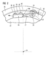
- the drive takes place via a housing 26 of the compressor 5 encompassing adjusting ring 26 which is coupled via levers 25 to the inlet blades 19.
- the adjusting ring 26 is rotatable about the central axis 24 in the circumferential direction.
- the blade carrier 22 designed as a guide blade carrier is substantially circular in cross-section and is encompassed by the concentric to its central axis 24 adjusting ring 26.
- the adjusting ring 26 serves to drive the radially extending inlet blades 19 of the compressor 5, the blades of which form a ring-shaped blade grid in the annular flow channel of the compressor 5 for adjusting the mass flow.
- the device for supporting the adjusting ring 26 can also be used or provided for an adjusting ring 26 which is used to drive adjustable guide vanes of the compressor 5.
- a plurality of one-armed levers 27 distributed over the circumference of the blade carrier 22 are provided, which have a fixed end 28 and a free end 30 opposite this.
- the fixed end 28 of the lever 27 is the carrier side, ie bolted to the blade carrier 22.
- two commercially available screws 42 are used for this purpose, which connects the clamped end 28 rigidly connected to the blade carrier 22.
- a roller 32 is provided, the axis of rotation 34 is aligned parallel to the central axis 24.
- the adjusting ring 26 has on its inner side 36 an endless circumferential annular groove 38, in which each roller 32 of the device engages so that they are on the groove bottom 40 of the annular groove 38 unrolled.
- Each lever 27 is configured in its dimensions such that it presses the rotatably mounted at its free end 30 roller 32 under a bias to the inner side 36 and to the groove bottom 40 of the annular groove 38.
- the dimension h can be specified, which is the distance between the axis of rotation 34 between biased position and relaxed position, d. H. without collar 26, describes.
- the device has an odd number, such as five or seven, such lever 27 to support the adjusting ring 26 concentrically about the central axis 24.
- an even number of levers 27 is also conceivable.
- Each lever 27, also referred to as a roller block, has at least one elongated hole 44 for one or preferably a plurality of screws 42 on its carrier-side fixed end 28.
- the lever 27 is slidable in the tangential direction before tightening, so that the distance considered in the radial direction of the rotation axis 34 and the central axis 24 can be adjusted, whereby the magnitude of the bias, with which the lever 27, the roller 32 at the inside 36 of the adjusting ring 26 or presses against the groove base 40, can be adjusted particularly easily.
- the use of two or more screws 42 prevents rotation of the lever 27 about a radial axis, for example about the longitudinal axis of a screw.
- rollers 32 whose axial width of the width of the annular groove 38 corresponds approximately to prevent tilting of the adjusting ring 26 and its axial displacement reliably. Accordingly, the rollers 32 guided by the groove walls guide the adjusting ring 26.
Landscapes
- Engineering & Computer Science (AREA)
- Mechanical Engineering (AREA)
- General Engineering & Computer Science (AREA)
- Structures Of Non-Positive Displacement Pumps (AREA)
- Processing Of Stones Or Stones Resemblance Materials (AREA)
- Tyre Moulding (AREA)
- Manufacture Of Motors, Generators (AREA)
- Grinding Of Cylindrical And Plane Surfaces (AREA)
- Coating Apparatus (AREA)
- Finish Polishing, Edge Sharpening, And Grinding By Specific Grinding Devices (AREA)
Priority Applications (4)
| Application Number | Priority Date | Filing Date | Title |
|---|---|---|---|
| DE502006001275T DE502006001275D1 (de) | 2006-01-02 | 2006-01-02 | Vorrichtung zur Abstützung eines einen kreisförmigen Schaufelträger beabstandet umgreifenden Stellrings |
| AT06000027T ATE403798T1 (de) | 2006-01-02 | 2006-01-02 | Vorrichtung zur abstützung eines einen kreisförmigen schaufelträger beabstandet umgreifenden stellrings |
| EP06000027A EP1803902B1 (fr) | 2006-01-02 | 2006-01-02 | Dispositif de support pour un anneau de réglage enveloppant un support d'aubes circulaire espacé |
| US11/649,141 US7828516B2 (en) | 2006-01-02 | 2007-01-03 | Device for support of an adjusting ring which encompasses at a distance a circular blade carrier |
Applications Claiming Priority (1)
| Application Number | Priority Date | Filing Date | Title |
|---|---|---|---|
| EP06000027A EP1803902B1 (fr) | 2006-01-02 | 2006-01-02 | Dispositif de support pour un anneau de réglage enveloppant un support d'aubes circulaire espacé |
Publications (2)
| Publication Number | Publication Date |
|---|---|
| EP1803902A1 true EP1803902A1 (fr) | 2007-07-04 |
| EP1803902B1 EP1803902B1 (fr) | 2008-08-06 |
Family
ID=36950203
Family Applications (1)
| Application Number | Title | Priority Date | Filing Date |
|---|---|---|---|
| EP06000027A Expired - Lifetime EP1803902B1 (fr) | 2006-01-02 | 2006-01-02 | Dispositif de support pour un anneau de réglage enveloppant un support d'aubes circulaire espacé |
Country Status (4)
| Country | Link |
|---|---|
| US (1) | US7828516B2 (fr) |
| EP (1) | EP1803902B1 (fr) |
| AT (1) | ATE403798T1 (fr) |
| DE (1) | DE502006001275D1 (fr) |
Cited By (1)
| Publication number | Priority date | Publication date | Assignee | Title |
|---|---|---|---|---|
| DE102011086031B4 (de) * | 2010-11-23 | 2016-02-04 | Bosch Mahle Turbo Systems Gmbh & Co. Kg | Variable Turbinengeometrie |
Families Citing this family (15)
| Publication number | Priority date | Publication date | Assignee | Title |
|---|---|---|---|---|
| EP2507907A4 (fr) * | 2009-11-30 | 2015-07-15 | Gerald L Barber | Turbine d'éolienne avec générateur électrique réglable |
| IT1401664B1 (it) | 2010-08-31 | 2013-08-02 | Nuova Pignone S R L | Dispositivo di centraggio e sistema per anello di guida. |
| US9284851B2 (en) * | 2012-02-21 | 2016-03-15 | Mitsubishi Heavy Industries, Ltd. | Axial-flow fluid machine, and variable vane drive device thereof |
| US9651053B2 (en) | 2014-01-24 | 2017-05-16 | Pratt & Whitney Canada Corp. | Bleed valve |
| US10125622B2 (en) | 2015-08-27 | 2018-11-13 | Rolls-Royce North American Technologies Inc. | Splayed inlet guide vanes |
| US10267159B2 (en) | 2015-08-27 | 2019-04-23 | Rolls-Royce North America Technologies Inc. | System and method for creating a fluidic barrier with vortices from the upstream splitter |
| US10233869B2 (en) | 2015-08-27 | 2019-03-19 | Rolls Royce North American Technologies Inc. | System and method for creating a fluidic barrier from the leading edge of a fan blade |
| US9976514B2 (en) | 2015-08-27 | 2018-05-22 | Rolls-Royce North American Technologies, Inc. | Propulsive force vectoring |
| US10718221B2 (en) | 2015-08-27 | 2020-07-21 | Rolls Royce North American Technologies Inc. | Morphing vane |
| US10267160B2 (en) | 2015-08-27 | 2019-04-23 | Rolls-Royce North American Technologies Inc. | Methods of creating fluidic barriers in turbine engines |
| US9915149B2 (en) | 2015-08-27 | 2018-03-13 | Rolls-Royce North American Technologies Inc. | System and method for a fluidic barrier on the low pressure side of a fan blade |
| US20170057649A1 (en) | 2015-08-27 | 2017-03-02 | Edward C. Rice | Integrated aircraft propulsion system |
| US10280872B2 (en) | 2015-08-27 | 2019-05-07 | Rolls-Royce North American Technologies Inc. | System and method for a fluidic barrier from the upstream splitter |
| TWI855391B (zh) | 2017-09-25 | 2024-09-11 | 美商江森自控技術公司 | 用於離心壓縮機之擴散器系統及用於用來壓縮流體的可變容量離心壓縮機之系統 |
| CN114961882A (zh) * | 2021-02-26 | 2022-08-30 | 中国航发商用航空发动机有限责任公司 | 可调静子叶片角度控制装置 |
Citations (6)
| Publication number | Priority date | Publication date | Assignee | Title |
|---|---|---|---|---|
| US3736070A (en) * | 1971-06-22 | 1973-05-29 | Curtiss Wright Corp | Variable stator blade assembly for axial flow, fluid expansion engine |
| DE2513581A1 (de) * | 1975-03-06 | 1976-09-09 | Bbc Brown Boveri & Cie | Turbinenregelung eines heizkraftwerkes |
| US4035101A (en) * | 1976-03-24 | 1977-07-12 | Westinghouse Electric Corporation | Gas turbine nozzle vane adjusting mechanism |
| US5035572A (en) * | 1989-04-21 | 1991-07-30 | Mtu Motoren-Und Turbinen-Union Munchen Gmbh | Arrangement for adjusting guide blades |
| US5549448A (en) | 1995-02-08 | 1996-08-27 | United Technolgies Corporation | Variable stator vane linkage system and method |
| EP1524413A2 (fr) | 2003-10-15 | 2005-04-20 | United Technologies Corporation | Manchon de palier en électro-graphite pour une aube variable |
Family Cites Families (7)
| Publication number | Priority date | Publication date | Assignee | Title |
|---|---|---|---|---|
| US3558237A (en) * | 1969-06-25 | 1971-01-26 | Gen Motors Corp | Variable turbine nozzles |
| DE2253030A1 (de) * | 1972-10-28 | 1974-05-09 | Sljusarew | Vorrichtung zur schaufelverstellung des leitapparats einer stroemungsmaschine |
| US3990809A (en) * | 1975-07-24 | 1976-11-09 | United Technologies Corporation | High ratio actuation linkage |
| CA1034509A (fr) * | 1975-10-14 | 1978-07-11 | Westinghouse Canada Limited | Commande de roue a aubes pour turbine a gaz |
| US5538214A (en) * | 1994-07-27 | 1996-07-23 | Sinila; Alexander | Locking accessory support apparatus |
| SE519353C2 (sv) * | 2000-11-15 | 2003-02-18 | Volvo Aero Corp | Stator till en gasturbin |
| DE10351202A1 (de) | 2003-11-03 | 2005-06-02 | Mtu Aero Engines Gmbh | Vorrichtung zum Verstellen von Leitschaufeln |
-
2006
- 2006-01-02 AT AT06000027T patent/ATE403798T1/de not_active IP Right Cessation
- 2006-01-02 EP EP06000027A patent/EP1803902B1/fr not_active Expired - Lifetime
- 2006-01-02 DE DE502006001275T patent/DE502006001275D1/de not_active Expired - Lifetime
-
2007
- 2007-01-03 US US11/649,141 patent/US7828516B2/en not_active Expired - Fee Related
Patent Citations (6)
| Publication number | Priority date | Publication date | Assignee | Title |
|---|---|---|---|---|
| US3736070A (en) * | 1971-06-22 | 1973-05-29 | Curtiss Wright Corp | Variable stator blade assembly for axial flow, fluid expansion engine |
| DE2513581A1 (de) * | 1975-03-06 | 1976-09-09 | Bbc Brown Boveri & Cie | Turbinenregelung eines heizkraftwerkes |
| US4035101A (en) * | 1976-03-24 | 1977-07-12 | Westinghouse Electric Corporation | Gas turbine nozzle vane adjusting mechanism |
| US5035572A (en) * | 1989-04-21 | 1991-07-30 | Mtu Motoren-Und Turbinen-Union Munchen Gmbh | Arrangement for adjusting guide blades |
| US5549448A (en) | 1995-02-08 | 1996-08-27 | United Technolgies Corporation | Variable stator vane linkage system and method |
| EP1524413A2 (fr) | 2003-10-15 | 2005-04-20 | United Technologies Corporation | Manchon de palier en électro-graphite pour une aube variable |
Cited By (1)
| Publication number | Priority date | Publication date | Assignee | Title |
|---|---|---|---|---|
| DE102011086031B4 (de) * | 2010-11-23 | 2016-02-04 | Bosch Mahle Turbo Systems Gmbh & Co. Kg | Variable Turbinengeometrie |
Also Published As
| Publication number | Publication date |
|---|---|
| US7828516B2 (en) | 2010-11-09 |
| ATE403798T1 (de) | 2008-08-15 |
| DE502006001275D1 (de) | 2008-09-18 |
| US20070154301A1 (en) | 2007-07-05 |
| EP1803902B1 (fr) | 2008-08-06 |
Similar Documents
| Publication | Publication Date | Title |
|---|---|---|
| EP1803902B1 (fr) | Dispositif de support pour un anneau de réglage enveloppant un support d'aubes circulaire espacé | |
| DE102012213227B3 (de) | Schaufelkranz für eine Turbomaschine | |
| EP2650490B1 (fr) | Dispositif de réglage d'aube directrice d'une turbine à gaz | |
| EP2362070A1 (fr) | Dispositif d'entraînement pour le pivotement d'aubes réglables d'une turbomachine | |
| DE4031478A1 (de) | Laufschaufelspitzenspaltbreitensteuer- vorrichtung mit nockenbetaetigter mantelringsegmentpositioniervorrichtung | |
| EP2386726B1 (fr) | Section de paroi de canal pour un canal d'écoulement annulaire d'une turbomachine axiale dotée d'un réglage du jeu en bout d'aube, compresseur axial et turbine à gaz associés | |
| DE4028330A1 (de) | Mechanische laufschaufelspitzenspaltbreitensteuervorrichtung fuer ein gasturbinentriebwerk | |
| DE4036693A1 (de) | Laufschaufelspitzenspaltbreitensteuer - vorrichtung mit mantelsegmenteinstellung durch gleichlaufring | |
| WO2010112421A1 (fr) | Turbomachine axiale à contrôle passif des jeux | |
| EP3000984A1 (fr) | Dispositif de reglage d'aube directrice d'une turbine a gaz | |
| EP2173972B1 (fr) | Rotor pour turbomachine à flux axial | |
| EP2342425A1 (fr) | Turbine à gaz avec plaque de fixation entre la base d'aube et le disque | |
| EP2233701A1 (fr) | Turbomachine axiale avec support d'aube directrice axialement mobile | |
| WO2010084028A1 (fr) | Système d'aubes directrices pour une turbomachine comportant un support d'aubes directrices segmenté | |
| DE112015003201B4 (de) | Wartungsverfahren für variable leitflügelvorrichtung und variable leitflügelvorrichtung | |
| WO2008043663A1 (fr) | Rotor pour une turbomachine | |
| DE102016122639A1 (de) | Leitschaufelbaugruppe mit Ausgleichseinrichtung | |
| EP2591213A2 (fr) | Compresseur et turbine à gaz associée | |
| EP2730751A2 (fr) | Dispositif de réglage d'aubes directrices d'une turbine à gaz | |
| WO2009109430A1 (fr) | Dispositif d’étanchéité et turbine à gaz | |
| EP3176386B1 (fr) | Système de virole interne, virole interne, boîtier intermédiaire et turbomachine associés | |
| DE60024519T2 (de) | Klemmring zur Fixierung von Kühlrohren in einem Gasturbinenrotor | |
| EP1860284A1 (fr) | Assemblage de carters | |
| EP1655455A1 (fr) | Dispositif pour régler le jeu radial des aubes de guidage d'une turbomachine | |
| EP3327256B1 (fr) | Ensemble d'aube directrice pourvu de dispositif de compensation |
Legal Events
| Date | Code | Title | Description |
|---|---|---|---|
| PUAI | Public reference made under article 153(3) epc to a published international application that has entered the european phase |
Free format text: ORIGINAL CODE: 0009012 |
|
| AK | Designated contracting states |
Kind code of ref document: A1 Designated state(s): AT BE BG CH CY CZ DE DK EE ES FI FR GB GR HU IE IS IT LI LT LU LV MC NL PL PT RO SE SI SK TR |
|
| AX | Request for extension of the european patent |
Extension state: AL BA HR MK YU |
|
| 17P | Request for examination filed |
Effective date: 20071022 |
|
| GRAP | Despatch of communication of intention to grant a patent |
Free format text: ORIGINAL CODE: EPIDOSNIGR1 |
|
| AKX | Designation fees paid |
Designated state(s): AT BE BG CH CY CZ DE DK EE ES FI FR GB GR HU IE IS IT LI LT LU LV MC NL PL PT RO SE SI SK TR |
|
| GRAS | Grant fee paid |
Free format text: ORIGINAL CODE: EPIDOSNIGR3 |
|
| GRAA | (expected) grant |
Free format text: ORIGINAL CODE: 0009210 |
|
| AK | Designated contracting states |
Kind code of ref document: B1 Designated state(s): AT BE BG CH CY CZ DE DK EE ES FI FR GB GR HU IE IS IT LI LT LU LV MC NL PL PT RO SE SI SK TR |
|
| REG | Reference to a national code |
Ref country code: GB Ref legal event code: FG4D Free format text: NOT ENGLISH |
|
| REG | Reference to a national code |
Ref country code: CH Ref legal event code: NV Representative=s name: SIEMENS SCHWEIZ AG Ref country code: CH Ref legal event code: EP |
|
| REG | Reference to a national code |
Ref country code: IE Ref legal event code: FG4D Free format text: LANGUAGE OF EP DOCUMENT: GERMAN |
|
| REF | Corresponds to: |
Ref document number: 502006001275 Country of ref document: DE Date of ref document: 20080918 Kind code of ref document: P |
|
| PG25 | Lapsed in a contracting state [announced via postgrant information from national office to epo] |
Ref country code: LT Free format text: LAPSE BECAUSE OF FAILURE TO SUBMIT A TRANSLATION OF THE DESCRIPTION OR TO PAY THE FEE WITHIN THE PRESCRIBED TIME-LIMIT Effective date: 20080806 Ref country code: IS Free format text: LAPSE BECAUSE OF FAILURE TO SUBMIT A TRANSLATION OF THE DESCRIPTION OR TO PAY THE FEE WITHIN THE PRESCRIBED TIME-LIMIT Effective date: 20081206 Ref country code: NL Free format text: LAPSE BECAUSE OF FAILURE TO SUBMIT A TRANSLATION OF THE DESCRIPTION OR TO PAY THE FEE WITHIN THE PRESCRIBED TIME-LIMIT Effective date: 20080806 |
|
| PG25 | Lapsed in a contracting state [announced via postgrant information from national office to epo] |
Ref country code: LV Free format text: LAPSE BECAUSE OF FAILURE TO SUBMIT A TRANSLATION OF THE DESCRIPTION OR TO PAY THE FEE WITHIN THE PRESCRIBED TIME-LIMIT Effective date: 20080806 Ref country code: FI Free format text: LAPSE BECAUSE OF FAILURE TO SUBMIT A TRANSLATION OF THE DESCRIPTION OR TO PAY THE FEE WITHIN THE PRESCRIBED TIME-LIMIT Effective date: 20080806 Ref country code: ES Free format text: LAPSE BECAUSE OF FAILURE TO SUBMIT A TRANSLATION OF THE DESCRIPTION OR TO PAY THE FEE WITHIN THE PRESCRIBED TIME-LIMIT Effective date: 20081117 Ref country code: SI Free format text: LAPSE BECAUSE OF FAILURE TO SUBMIT A TRANSLATION OF THE DESCRIPTION OR TO PAY THE FEE WITHIN THE PRESCRIBED TIME-LIMIT Effective date: 20080806 |
|
| REG | Reference to a national code |
Ref country code: IE Ref legal event code: FD4D |
|
| REG | Reference to a national code |
Ref country code: CH Ref legal event code: PCAR Free format text: SIEMENS SCHWEIZ AG;INTELLECTUAL PROPERTY FREILAGERSTRASSE 40;8047 ZUERICH (CH) |
|
| PG25 | Lapsed in a contracting state [announced via postgrant information from national office to epo] |
Ref country code: BG Free format text: LAPSE BECAUSE OF FAILURE TO SUBMIT A TRANSLATION OF THE DESCRIPTION OR TO PAY THE FEE WITHIN THE PRESCRIBED TIME-LIMIT Effective date: 20081106 Ref country code: DK Free format text: LAPSE BECAUSE OF FAILURE TO SUBMIT A TRANSLATION OF THE DESCRIPTION OR TO PAY THE FEE WITHIN THE PRESCRIBED TIME-LIMIT Effective date: 20080806 Ref country code: IE Free format text: LAPSE BECAUSE OF FAILURE TO SUBMIT A TRANSLATION OF THE DESCRIPTION OR TO PAY THE FEE WITHIN THE PRESCRIBED TIME-LIMIT Effective date: 20080806 |
|
| PG25 | Lapsed in a contracting state [announced via postgrant information from national office to epo] |
Ref country code: CZ Free format text: LAPSE BECAUSE OF FAILURE TO SUBMIT A TRANSLATION OF THE DESCRIPTION OR TO PAY THE FEE WITHIN THE PRESCRIBED TIME-LIMIT Effective date: 20080806 Ref country code: SK Free format text: LAPSE BECAUSE OF FAILURE TO SUBMIT A TRANSLATION OF THE DESCRIPTION OR TO PAY THE FEE WITHIN THE PRESCRIBED TIME-LIMIT Effective date: 20080806 Ref country code: RO Free format text: LAPSE BECAUSE OF FAILURE TO SUBMIT A TRANSLATION OF THE DESCRIPTION OR TO PAY THE FEE WITHIN THE PRESCRIBED TIME-LIMIT Effective date: 20080806 Ref country code: PT Free format text: LAPSE BECAUSE OF FAILURE TO SUBMIT A TRANSLATION OF THE DESCRIPTION OR TO PAY THE FEE WITHIN THE PRESCRIBED TIME-LIMIT Effective date: 20090106 |
|
| PLBE | No opposition filed within time limit |
Free format text: ORIGINAL CODE: 0009261 |
|
| STAA | Information on the status of an ep patent application or granted ep patent |
Free format text: STATUS: NO OPPOSITION FILED WITHIN TIME LIMIT |
|
| 26N | No opposition filed |
Effective date: 20090507 |
|
| PG25 | Lapsed in a contracting state [announced via postgrant information from national office to epo] |
Ref country code: EE Free format text: LAPSE BECAUSE OF FAILURE TO SUBMIT A TRANSLATION OF THE DESCRIPTION OR TO PAY THE FEE WITHIN THE PRESCRIBED TIME-LIMIT Effective date: 20080806 |
|
| PG25 | Lapsed in a contracting state [announced via postgrant information from national office to epo] |
Ref country code: MC Free format text: LAPSE BECAUSE OF NON-PAYMENT OF DUE FEES Effective date: 20090131 |
|
| PG25 | Lapsed in a contracting state [announced via postgrant information from national office to epo] |
Ref country code: SE Free format text: LAPSE BECAUSE OF FAILURE TO SUBMIT A TRANSLATION OF THE DESCRIPTION OR TO PAY THE FEE WITHIN THE PRESCRIBED TIME-LIMIT Effective date: 20081106 |
|
| PG25 | Lapsed in a contracting state [announced via postgrant information from national office to epo] |
Ref country code: BE Free format text: LAPSE BECAUSE OF NON-PAYMENT OF DUE FEES Effective date: 20090131 |
|
| PG25 | Lapsed in a contracting state [announced via postgrant information from national office to epo] |
Ref country code: PL Free format text: LAPSE BECAUSE OF FAILURE TO SUBMIT A TRANSLATION OF THE DESCRIPTION OR TO PAY THE FEE WITHIN THE PRESCRIBED TIME-LIMIT Effective date: 20080806 |
|
| PG25 | Lapsed in a contracting state [announced via postgrant information from national office to epo] |
Ref country code: AT Free format text: LAPSE BECAUSE OF NON-PAYMENT OF DUE FEES Effective date: 20090102 |
|
| PG25 | Lapsed in a contracting state [announced via postgrant information from national office to epo] |
Ref country code: GR Free format text: LAPSE BECAUSE OF FAILURE TO SUBMIT A TRANSLATION OF THE DESCRIPTION OR TO PAY THE FEE WITHIN THE PRESCRIBED TIME-LIMIT Effective date: 20081107 |
|
| PG25 | Lapsed in a contracting state [announced via postgrant information from national office to epo] |
Ref country code: LU Free format text: LAPSE BECAUSE OF NON-PAYMENT OF DUE FEES Effective date: 20090102 |
|
| PG25 | Lapsed in a contracting state [announced via postgrant information from national office to epo] |
Ref country code: HU Free format text: LAPSE BECAUSE OF FAILURE TO SUBMIT A TRANSLATION OF THE DESCRIPTION OR TO PAY THE FEE WITHIN THE PRESCRIBED TIME-LIMIT Effective date: 20090207 |
|
| PG25 | Lapsed in a contracting state [announced via postgrant information from national office to epo] |
Ref country code: TR Free format text: LAPSE BECAUSE OF FAILURE TO SUBMIT A TRANSLATION OF THE DESCRIPTION OR TO PAY THE FEE WITHIN THE PRESCRIBED TIME-LIMIT Effective date: 20080806 |
|
| PG25 | Lapsed in a contracting state [announced via postgrant information from national office to epo] |
Ref country code: CY Free format text: LAPSE BECAUSE OF FAILURE TO SUBMIT A TRANSLATION OF THE DESCRIPTION OR TO PAY THE FEE WITHIN THE PRESCRIBED TIME-LIMIT Effective date: 20080806 |
|
| REG | Reference to a national code |
Ref country code: FR Ref legal event code: PLFP Year of fee payment: 11 |
|
| PGFP | Annual fee paid to national office [announced via postgrant information from national office to epo] |
Ref country code: CH Payment date: 20160404 Year of fee payment: 11 |
|
| REG | Reference to a national code |
Ref country code: FR Ref legal event code: PLFP Year of fee payment: 12 |
|
| PGFP | Annual fee paid to national office [announced via postgrant information from national office to epo] |
Ref country code: DE Payment date: 20170320 Year of fee payment: 12 Ref country code: FR Payment date: 20170117 Year of fee payment: 12 |
|
| PGFP | Annual fee paid to national office [announced via postgrant information from national office to epo] |
Ref country code: GB Payment date: 20170109 Year of fee payment: 12 |
|
| PGFP | Annual fee paid to national office [announced via postgrant information from national office to epo] |
Ref country code: IT Payment date: 20170127 Year of fee payment: 12 |
|
| REG | Reference to a national code |
Ref country code: CH Ref legal event code: PL |
|
| PG25 | Lapsed in a contracting state [announced via postgrant information from national office to epo] |
Ref country code: LI Free format text: LAPSE BECAUSE OF NON-PAYMENT OF DUE FEES Effective date: 20170131 Ref country code: CH Free format text: LAPSE BECAUSE OF NON-PAYMENT OF DUE FEES Effective date: 20170131 |
|
| REG | Reference to a national code |
Ref country code: DE Ref legal event code: R119 Ref document number: 502006001275 Country of ref document: DE |
|
| GBPC | Gb: european patent ceased through non-payment of renewal fee |
Effective date: 20180102 |
|
| PG25 | Lapsed in a contracting state [announced via postgrant information from national office to epo] |
Ref country code: DE Free format text: LAPSE BECAUSE OF NON-PAYMENT OF DUE FEES Effective date: 20180801 Ref country code: FR Free format text: LAPSE BECAUSE OF NON-PAYMENT OF DUE FEES Effective date: 20180131 |
|
| REG | Reference to a national code |
Ref country code: FR Ref legal event code: ST Effective date: 20180928 |
|
| PG25 | Lapsed in a contracting state [announced via postgrant information from national office to epo] |
Ref country code: GB Free format text: LAPSE BECAUSE OF NON-PAYMENT OF DUE FEES Effective date: 20180102 |
|
| PG25 | Lapsed in a contracting state [announced via postgrant information from national office to epo] |
Ref country code: IT Free format text: LAPSE BECAUSE OF NON-PAYMENT OF DUE FEES Effective date: 20180102 |