EP1804031A2 - Magnetische Vorrichtung zur Detektion des Positionswinkels - Google Patents
Magnetische Vorrichtung zur Detektion des Positionswinkels Download PDFInfo
- Publication number
- EP1804031A2 EP1804031A2 EP06026031A EP06026031A EP1804031A2 EP 1804031 A2 EP1804031 A2 EP 1804031A2 EP 06026031 A EP06026031 A EP 06026031A EP 06026031 A EP06026031 A EP 06026031A EP 1804031 A2 EP1804031 A2 EP 1804031A2
- Authority
- EP
- European Patent Office
- Prior art keywords
- magnetic
- generating element
- magnetic line
- sensor
- detecting device
- Prior art date
- Legal status (The legal status is an assumption and is not a legal conclusion. Google has not performed a legal analysis and makes no representation as to the accuracy of the status listed.)
- Withdrawn
Links
Images



Classifications
-
- G—PHYSICS
- G01—MEASURING; TESTING
- G01D—MEASURING NOT SPECIALLY ADAPTED FOR A SPECIFIC VARIABLE; ARRANGEMENTS FOR MEASURING TWO OR MORE VARIABLES NOT COVERED IN A SINGLE OTHER SUBCLASS; TARIFF METERING APPARATUS; MEASURING OR TESTING NOT OTHERWISE PROVIDED FOR
- G01D5/00—Mechanical means for transferring the output of a sensing member; Means for converting the output of a sensing member to another variable where the form or nature of the sensing member does not constrain the means for converting; Transducers not specially adapted for a specific variable
- G01D5/12—Mechanical means for transferring the output of a sensing member; Means for converting the output of a sensing member to another variable where the form or nature of the sensing member does not constrain the means for converting; Transducers not specially adapted for a specific variable using electric or magnetic means
- G01D5/14—Mechanical means for transferring the output of a sensing member; Means for converting the output of a sensing member to another variable where the form or nature of the sensing member does not constrain the means for converting; Transducers not specially adapted for a specific variable using electric or magnetic means influencing the magnitude of a current or voltage
- G01D5/142—Mechanical means for transferring the output of a sensing member; Means for converting the output of a sensing member to another variable where the form or nature of the sensing member does not constrain the means for converting; Transducers not specially adapted for a specific variable using electric or magnetic means influencing the magnitude of a current or voltage using Hall-effect devices
- G01D5/145—Mechanical means for transferring the output of a sensing member; Means for converting the output of a sensing member to another variable where the form or nature of the sensing member does not constrain the means for converting; Transducers not specially adapted for a specific variable using electric or magnetic means influencing the magnitude of a current or voltage using Hall-effect devices influenced by the relative movement between the Hall device and magnetic fields
-
- G—PHYSICS
- G01—MEASURING; TESTING
- G01R—MEASURING ELECTRIC VARIABLES; MEASURING MAGNETIC VARIABLES
- G01R33/00—Arrangements or instruments for measuring magnetic variables
- G01R33/02—Measuring direction or magnitude of magnetic fields or magnetic flux
- G01R33/06—Measuring direction or magnitude of magnetic fields or magnetic flux using galvano-magnetic devices
- G01R33/07—Hall effect devices
- G01R33/072—Constructional adaptation of the sensor to specific applications
-
- G—PHYSICS
- G01—MEASURING; TESTING
- G01R—MEASURING ELECTRIC VARIABLES; MEASURING MAGNETIC VARIABLES
- G01R33/00—Arrangements or instruments for measuring magnetic variables
- G01R33/02—Measuring direction or magnitude of magnetic fields or magnetic flux
- G01R33/06—Measuring direction or magnitude of magnetic fields or magnetic flux using galvano-magnetic devices
- G01R33/09—Magnetoresistive devices
- G01R33/091—Constructional adaptation of the sensor to specific applications
Definitions
- the present invention relates to a position-angle detection device of a magnetic line-type, which is used in various machines and equipments for detecting the position.
- a magnetic sensor array is constructed with a plurality of magnetic sensor elements arranged in a matrix pattern and is arranged in face-to-face relation with a magnet, arranged on a rotatable member, so as to detect a distribution of magnetic fields generated by the magnet, so that the angle of rotation of the magnet can be detected from the detected distribution of the magnetic fields.
- the position sensors of the optical, electrostatic capacitance detecting and magnetic types referred to above involves various problems in that they are expensive, require adjustments and are capable of only detecting a relative displacement.
- An object of the present invention is to provide a magnetic line-type position-angle detecting device capable of detecting the absolute position on a non-contact basis and with high resolution and, also, capable of being inexpensively constructed.
- the magnetic line-type position-angle detecting device includes a magnetic line sensor having a plurality of magnetic sensor elements arranged in a linear array, a magnetic generating element held in face-to-face relation with the magnetic line sensor and movable along the magnetic line sensor in a direction conforming to the direction in which the magnetic sensor elements are deployed, a scanning circuit for sequentially selecting one of the magnetic sensor elements of the magnetic line sensor, an amplifier for amplifying a signal outputted from the selected sensor element, an analog-to-digital converting circuit for converting an output from the amplifier into a digital signal, and a calculation processing circuit for evaluating a distribution of magnetic fields, applied to the magnetic line sensor, in reference to an output of the analog-to-digital converting circuit to thereby calculate a position of the magnetic generating element.
- the magnetic generating element referred to above may include a magnet having a pair of N and S magnetic poles confronting the magnetic line sensor, and the calculation processing circuit referred to above may be of a type capable of detecting the position of the magnetic generating element in reference to a waveform of a sensor signal obtained from the output of the analog-to-digital converting circuit.
- the calculation processing circuit referred to above may be of a type capable of detecting a zero-crossing position of a waveform of a sensor signal outputted from the analog-to-digital converting circuit. Also, the calculation processing circuit may be of a type capable of converting the zero-crossing position into an actual position of the magnetic generating element to thereby calculate and output an absolute position.
- magnetic lines generated from the magnetic generating element are applied to the magnetic line sensor and the magnetic sensor elements then detect the applied magnetisms, respectively.
- Each of the magnetic sensor element of the magnetic line sensor is sequentially selected by the scanning circuit, a detection signal of the selected magnetic sensor element is then amplified by the amplifier, and an output of the amplifier is subsequently converted into a digital signal by the analog-to-digital (AD) converting circuit.
- AD analog-to-digital
- the zero-crossing position is determined from a plurality of detection signals in the vicinity of a boundary position (the zero-crossing position) of the magnetic poles in the distribution of the magnetic fields, generated by the magnetic generating element, by means of a collinear approximation so that this zero-crossing position can be calculated as the position of the magnetic generating element.
- the position of the magnetic generating element moving linearly can be detected as the absolute position on a non-contact basis with avoiding frictional wear.
- the position of the magnetic generating element can be detected with higher resolution than the array pitch of the magnetic sensor elements of the magnetic line sensor and without being affected by the absolute value (intensity) of the magnetic field strength. Also, since the collinear approximation is calculated using the plurality of the detection signals in the vicinity of the zero, noise components contained in those detection signals can be averaged, bringing about such an effect as to render it to be hardly affected by noises.
- the magnetic line sensors may be arranged in a square form and the calculation processing circuit may be of a type capable of detecting the angle and the position of the magnetic generating element simultaneously.
- the calculation processing circuit may be of a type capable of detecting the angle and the position of the magnetic generating element simultaneously.
- the magnetic generating element may have two polar boundaries in a direction in which the sensor elements of the magnetic line sensor are arranged.
- the calculation processing circuit referred to above may be of a type capable of detecting the position of the magnetic generating element by detecting two zero-crossing positions obtained from a waveform of the sensor signal outputted from the AD converting circuit. Also, the calculation processing circuit referred to above may be of a type capable of determining an intermediate point from the two detected zero-crossing positions for outputting the detected position of the magnetic generating element. In the case of this construction, it is possible to render the detection of the position of the magnetic generating element to be hardly affected by external magnetic fields and the precision of the angle detection can correspondingly be increased.
- magnetic lines generated from the magnetic generating element are applied to the magnetic line sensor and the magnetic sensor elements then detect the applied magnetisms, respectively.
- Each of the magnetic sensor elements of the magnetic line sensor is sequentially selected by the scanning circuit, a detection signal of the selected magnetic sensor element is then amplified by the amplifier, and an output of the amplifier is subsequently converted into a digital signal by the analog-to-digital (AD) converting circuit.
- AD analog-to-digital
- two zero-crossing positions are determined from a plurality of detection signals in the vicinity of a position of two magnetic polar boundaries (the zero-crossing positions) in the distribution of the magnetic fields, generated by the magnetic generating element, by means of, for example, a collinear approximation, and an intermediate point of the determined two zero-crossing positions is then calculated so that the intermediate point can be outputted as the position of the magnetic generating element.
- the position of the magnetic generating element moving linearly can be detected as the absolute position on a non-contact basis while avoiding frictional wear.
- the position of the magnetic generating element can be detected with higher resolution than the array pitch of the magnetic sensor elements of the magnetic line sensor and without being affected by the absolute value (intensity) of the magnetic field strength. Also, since the collinear approximation is calculated using the plurality of the detection signals in the vicinity of the zero, noise components contained in those detection signals can be averaged, bringing about such an effect as to render it to be hardly affected by noises.
- the magnetic line-type position-angle detecting device may be of a structure, in which the magnetic generating element is angularly movable generally along the magnetic line sensor in a direction, conforming to the direction in which the magnetic sensor elements are deployed, on an arcuate path about a predetermined rotation axis, and the calculation processing circuit is capable of measuring a distribution of magnetic fields applied to the magnetic line sensor for detecting the position of the magnetic generating element above the line sensor, and capable of determining from the detected position, an angle at which the magnetic generating element is positioned about the rotation axis, that is, a magnetic line-type position-angle detecting device.
- the magnetic line-type position-angle detecting device referred to above may include an integrated circuit of a silicon chip.
- the calculation processing circuit may include a parameter storage for storing such parameters as a distance of arrangement of the magnetic generating element from the rotation axis and a position of origin of the angle of the magnetic generating element, and the parameters to be stored in the parameter storage can be set from outside of the calculation processing circuit.
- the calculation processing circuit may be capable of detecting the position of the magnetic generating element above the magnetic line sensor, by utilizing the parameters stored in the parameter storage, to thereby calculate an absolute angle from the detected position data.
- the magnetic line-type position-angle detecting device magnetic fields from the magnetic generating element are applied to the magnetic line sensor and the magnetic sensor elements detects the magnetic fields then applied to the magnetic line sensor.
- the magnetic sensor elements are sequentially selected one after another by the scanning circuit, and a detection signal from the selected magnetic sensor element is amplified by the amplifier, before an output of the amplifier is converted by the AD converting circuit into a digital signal.
- the zero-crossing position is determined by performing, for example, a collinear approximation from a plurality of detection signals in the vicinity of a magnetic pole boundary (a zero-crossing position) in the distribution of the magnetic fields from the magnetic generating element and this zero-crossing position is outputted as the position of the magnetic generating element.
- the calculation processing circuit determines the angle of the magnetic generating element about the swinging axis from the position of the magnetic generating element, detected at a position of origin of a swinging motion. Thereby, the angle of the magnetic generating element can be detected on a non-contact basis with no frictional wear and with higher resolution than the array pitch of the magnetic sensor elements of the magnetic line sensor. Since the swing angle of the magnetic generating element is determined by such calculation processing, the minute angle can be detected with high precision when the distance from the position of the magnetic generating element, detected at the position of the origin of swing to the swinging axis is increased. It is, however, to be noted that increase of the above discussed distance may reduce the range of angle that can be detected and, therefore, this magnetic line-type position-angle detecting device is particularly suited to the detection with high resolution within a certain range of angle.
- the magnetic generating element For component parts of this magnetic line-type position-angle detecting device, the magnetic generating element, the silicon chip having the magnetic line sensor and the various signal processing circuits integrated thereon, a circuit substrate attendant to the silicon chip and casings are sufficient and the number of the component parts used is therefore small and, since no external correcting circuit is needed, the structure can be constructed simple and compact.
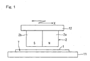
- FIG. 1 illustrates a basic structure of a magnetic line-type position-angle detecting device according to this first embodiment.
- This magnetic line-type position-angle detecting device includes a sensor chip 7 having a magnetic line sensor 1 (Fig. 2B), and a magnetic generating element 2 held in face-to-face relation with the magnetic line sensor 1 spacedly on a non-contact basis and movable in a direction X, in which sensor elements of the magnetic line sensor 1 are arrayed.
- the sensor chip 7 is fixed to a stationary side member 11 whereas the magnetic generating element 2 is fixed to a movable side member 12 capable of linearly moving in parallel to the longitudinal direction of the sensor chip 7.
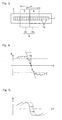
- the magnetic line sensor 1 is a sensor operable to detect magnetism of the magnetic generating element 2 and is made up of a plurality of sensor elements 1a arrayed in line on a surface of the single sensor chip 7 as shown in Fig. 2B. As shown in Fig.
- the sensor chip 7 includes a scanning circuit 3 for sequentially selecting one of the magnetic sensor elements 1a of the magnetic line sensor 1, an amplifier 4 for amplifying a signal from the selected magnetic sensor element 1a, an analog-to-digital (AD) converting circuit 5 for converting an output of the amplifier 4 to a digital signal, and a calculation processing circuit 6 for evaluating a distribution of magnetic fields, applied to the magnetic line sensor 1, based on the converted signal from AD converting circuit 5 to thereby calculate the position of the magnetic generating element 2, all of those elements being integrated on the sensor chip 7 together with the magnetic line sensor 1.
- AD analog-to-digital
- the magnetic generating element 2 is in the form of a magnet held in face-to-face relation with the magnetic line sensor 1 and having a pair of N and S magnetic poles 2a and 2b juxtaposed in the direction X, in which the sensor elements are arranged in line.
- the relation in position between the magnetic line sensor 1 and the magnetic generating element 2 is shown in a plan view.
- the magnetic line-type position-angle detecting device of the structure described above In a condition, in which the magnetic generating element 2 is held in, for example, such a relation in position as shown in Fig. 3 relative to the magnetic line sensor 1, a vertical component of magnetic fields generated from the magnetic generating element 2 in a direction perpendicular to the sensor chip 7 is applied to the magnetic line sensor 1 and each of the magnetic sensor elements 1a then detects the magnetic fields so applied.
- the magnetic sensor elements 1a of the magnetic line sensor 1 are sequentially selected one after another by the scanning circuit 3, and a detection signal from the selected magnetic sensor element 1a is amplified by the amplifier 4, before the output of the amplifier 4 is converted by the AD converting circuit 5 into a digital signal.
- Fig. 4 is a chart, in which respective detection signals of the magnetic sensor elements 1a obtained through such a signal processing as described above are plotted in the order of reading of those detection signals, which corresponds to a distribution of the magnetic fields generated by the magnetic generating element 2.
- a portion of the waveform on a positive (+) area corresponds to the magnetic field emanating from the S magnetic pole 2b of the magnetic generating element 2
- a portion of the waveform on a negative (-) area corresponds to the magnetic field emanating from the N magnetic pole 2a of the magnetic generating element 2.
- a detection signal in the vicinity of a boundary position (zero-crossing position) X0 between the N and S magnetic poles 2a and 2b approximates to a zero output since the vertical component of the magnetic fields applied there is zero.
- the zero-crossing position X0 is calculated from the plural detection signals in the vicinity of zero by means of a collinear approximation as shown by a linear line L in Fig. 4 and the zero-crossing position X0 so calculated is then determined as the position of the magnetic generating element 2.
- the least square method or the like can be employed.
- the position X0 of the magnetic generating element 2 so calculated is the absolute position on the magnetic line sensor 1
- no operation to ascertain the point of origin is needed and the current position can be detected immediately after the electric power-on operation.
- the position X0 of the magnetic generating element 2 can be detected with higher resolution than the array pitch of the magnetic sensor elements 1a of the magnetic line sensor 1 and without being affected by the sensitivity deviation of the magnetic sensor elements 1a and the absolute value (intensity) of the magnetic field strength.
- noise components contained in those detection signals can be averaged and, therefore, an effect of rendering it to be hardly affected by noises can also be obtained.
- the waveform of the detection signals plotted in Fig. 4 will shift from the waveform shown by the solid line in Fig. 5 to such a waveform as shown by the broken line in Fig. 5 and consequent upon this shift, the zero-crossing position X0, calculated by the calculation processing circuit 6 as the position of the magnetic generating element 2, changes. Therefore, the position of the magnetic generating element 2 then moving linearly, that is, the position to which the movable side member 12 is moved, can be detected as the absolute position on a non-contact basis while avoiding frictional wear involved.
- the collinear approximation is carried out to determine the zero-crossing position X0, the position of the magnetic generating element 2 can be detected with higher resolution than the array pitch of the magnetic sensor elements 1a of the magnetic line sensor 1 and without being affected by the absolute value (intensity) of the magnetic field strength. Also, since the collinear approximation is calculated using the plural detection signals in the vicinity of zero, noise components contained in those detection signals can be averaged and, hence, such an effect as to render it to be hardly affected by noises can be obtained.
- the magnetic line sensor 1 since a permanent magnet forming the magnetic generating element 2, the magnetic line sensor 1, a circuit substrate attendant to the magnetic line sensor 1 and casings are sufficient as component parts of the magnetic sensor type position sensor and the number of component parts used is therefore small and since no external correcting circuit is needed, it can be constructed simply and inexpensively.
- the coordinates of the zero-crossing position X0 determined by the collinear approximation may be outputted after having been converted into an actual position of the magnetic generating element 2.
- a certain position may be stored as a reference position (0) and the position of the magnetic generating element 2 may then be outputted in the form of a position which is +300 ⁇ m relative to the reference position.
- the calculation processing circuit 6 discussed above has to be provided with a unit for applying the reference position from outside and a nonvolatile memory for the storage of the reference position.
- Fig. 6 illustrates a second preferred embodiment of the present invention.
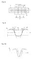
- This magnetic line-type position-angle detecting device is similar to that according to the previously described embodiment, but differs therefrom in that four magnetic line sensors 1A to 1D are arranged on the sensor chip 7 in a square pattern as shown therein.
- the scanning circuit 3 corresponding to the respective magnetic line sensor, the amplifier 4, the AD converting circuit 5 and the calculation processing circuit 6 are arranged.
- the magnetic generating elements 2 (Fig. 1) is not shown here, the structure thereof is identical with that in the previously described embodiment.
- the direction in which the pair of the N and S magnetic poles 2a and 2b of the magnetic generating element 2 are arranged has no particular relation with the direction in which the sensor elements of the magnetic line sensors 1A to 1D are arranged.
- This magnetic line-type position-angle detecting device is of a design, in which the magnetic line sensors on each pair of the opposite sides of the square pattern of arrangement of the four magnetic line sensors 1A to 1D, are utilized to determine the angle and the position of movement of the magnetic generating element 2.
- the boundary position (the zero-crossing position) of the pair of the N and S magnetic poles 2a and 2b of the magnetic generating element 2 lies at respective locations Z1 and Z2 on, for example, the magnetic line sensors 1B and 1D on the opposite sides is calculated by the calculation processing circuits 6, associated with those magnetic line sensors, on the basis of respective detection signals of the magnetic line sensors 1B and 1D and, at the same time, the angle of a zero line L1 connecting the zero-crossing positions Z1 and Z2 and the position of the zero line L1 on the sensor chip 7 are simultaneously determined by the utilization of the coordinates of the zero-crossing positions Z1 and Z2 at two points.
- the zero line L1 in this case represents a boundary line between N and S magnetic pole regions in the distribution of the magnetic fields emanating from the magnetic generating element 2.
- Calculation to determine the position and the angle of the zero line L1 from the zero-crossing positions Z1 and Z2 at those two points may be performed either by one of the calculation processing circuits 6 corresponding respectively to the four magnetic line sensors 1A to 1D or by a dedicated calculation processing circuit separately arranged on the sensor chip 7.
- Fig. 9 is a chart, in which respective detection signals of the magnetic sensor elements 1a obtained through such a signal processing as described above are plotted in the order of reading of those detection signals, which corresponds to a distribution of the magnetic fields generated by the magnetic generating element 2.
- a portion of the waveform on a positive (+) area corresponds to the magnetic fields emanating from the N magnetic poles 2a and 2c of the magnetic generating element 2
- a portion of the waveform on a negative (-) area corresponds to the magnetic field emanating from the S magnetic pole 2b of the magnetic generating element 2.
- a detection signal in the vicinity of a boundary position (zero-crossing position) X01 between the N and S magnetic poles 2a and 2b and a detection signal in the vicinity of a zero-crossing position X02 between the S and N magnetic poles 2b and 2c respectively approximate to a zero output since the vertical components of the magnetic fields applied therefore are zero.
- the zero-crossing positions X01 and X02 are calculated from the plural detection signals in the vicinity of zero at those two locations by means of a collinear approximation as shown by linear lines L1 and L2 in Fig. 9, and a point X0 intermediate between the zero-crossing positions X01 and X02 so calculated is then calculated and determined as the position of the magnetic generating element 2.
- the least square method or the like can be employed.
- the waveform of the detection signals plotted in Fig. 9 will change from the waveform, shown by the solid line in Fig. 10 to such a waveform as shown by the broken line in Fig. 10 and consequent upon this shift, the position X0, calculated by the calculation processing circuit 6 as the position of the magnetic generating element 2, changes. Therefore, the position of the magnetic generating element 2 then moving linearly, that is, the position to which the movable side member 12 is moved, can be detected as the absolute position on a non-contact basis while avoiding frictional wear involved.
- the above described waveform of the detection signal will change from the waveform, shown by the solid line in Fig. 11 to such a waveform as shown by the broken line in Fig. 11, when an disturbing magnetic field is applied, and the single zero-crossing positions X01 and X02 are consequently shifted by an equal quantity to respective positions X01' and X02'.
- the two zero-crossing positions X01 and X02 are determined by means of the collinear approximation of the plural signals in the vicinity of zero at the two locations out from the detection signals outputted from the magnetic line sensor 1, and the point X0 intermediate between the zero-crossing positions X01 and X02 so determined is calculated for outputting the intermediate point X0 as the position of the magnetic generating element 2.
- the collinear approximation is calculated using the plurality of the detection signals in the vicinity of the zero, noise components contained in those detection signals can be averaged, bringing about such an effect as to render it to be hardly affected by noises.
- the magnetic generating element 2 the magnetic line sensor 1, a circuit substrate attendant to the magnetic line sensor 1 and casings are sufficient as component parts of the magnetic sensor type position sensor and the number of component parts used is therefore small and since no external correcting circuit is needed, it can be constructed simply and inexpensively.
- the coordinates of the zero-crossing position X0 determined in the manner described above may be outputted after having been converted into an actual position of the magnetic generating element 2.
- a certain position may be stored as a reference position (0) and the position of the magnetic generating element 2 may then be outputted in the form of a position which is +300 ⁇ m relative to the reference position.
- the calculation processing circuit 6 discussed above has to be provided with a unit for applying the reference position from outside and an nonvolatile memory for the storage of the reference position.
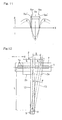
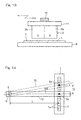
- the magnetic line-type position-angle detecting device includes a magnetic line sensor 1 having a plurality of magnetic sensor elements 1a arranged in a linear array, and a magnetic generating element 2 held in face-to-face relation with the magnetic line sensor 1 on a non-contact basis and angularly movable generally along the magnetic line sensor 1 in a direction, conforming to the direction X in which the magnetic sensor elements 1a are deployed, on an arcuate path about a predetermined rotation axis O.
- the magnetic line sensor 1 is provided on a silicon chip 7 as one of integrated circuit components, which chip 7 is fixed on a stationary side member 8 as shown in Fig. 13.
- the magnetic generating element 2 is fitted through a magnet support base 11, as shown in Fig. 13, to a free end of a swing arm 10 having a base end, that is rotatably supported on the stationary side member 8 through a pivot shaft 9 defining the rotation axis O as shown in Fig. 12, so that the magnetic generating element 2 can swing and move together with the swing arm 10.
- the magnet support base 11 is omitted in Fig. 12.
- the waveform of the detection signals plotted in Fig. 4 will shift from the waveform, shown by the solid line in Fig. 5 to such a waveform as shown by the broken line in Fig. 5 when the magnetic generating element 2 moves in, for example, a rightward direction in Fig. 3, and consequent upon this shift, calculation to determine the angle at the position of the magnetic generating element 2 calculated by the calculation processing circuit 6 as the zero-crossing position is carried out in the following manner.
- Fig. 14 is an explanatory diagram of the angle calculating process referred to above.
- the swing angle ⁇ of the magnetic generating element 2 can be detected on a non-contact basis while avoiding frictional wear.
- the calculation processing circuit 6 has a parameter storage (not shown) for storing various parameters required to accomplish the above described calculation such as, for example, the distance L of arrangement of the magnetic generating element 2 from the axis O of swing, and the position of origin (the position of origin of the swinging motion) of the angle of the magnetic generating element 2.
- This parameter storage is of a type in which those parameters to be stored can be set from outside of the calculation processing circuit 6.
- the resolution of detection of the position is limited by the structure of the sensor elements 1a of the magnetic line sensor 1 and noise characteristics, but increase of the distance L, from the detection position X0 of the magnetic generating element 2 at a reference swing position to the axis O of swing, is effective to accomplish the detection of a minute angle with high accuracy.
- the position detecting precision is 10 ⁇ m
- increase of the distance L reduces the detachable range of angle and, therefore, this magnetic line sensor type angle detecting device is particularly suited to the detection with high resolution within a certain range of angle.
- the magnetic line sensor 1 is of a system of detecting the zero-crossing position, the zero-crossing position is not affected by changes in the sensitivity of the magnetic sensor elements 1a and the magnetic field strength and, therefore, the stable detection of the position is possible. Accordingly, there is no need to control the gap distance between the magnetic line sensor 1 and the magnetic generating element 2, and assemblage and adjustment can therefore be accomplished easily
- This magnetic line-type position-angle detecting device may suffice to include the small number of component parts such as the magnetic generating element 2, the silicon chip 7 having the magnetic line sensor 1 and the various signal processing circuits 3 to 6 integrated thereon, a circuit substrate attendant to the silicon chip 7 and casings, and, no external correcting circuit is needed. Therefore the structure can be constructed simple and compact.
- a fifth preferred embodiment of the present invention is shown in Fig. 15.
- the magnetic line-type position-angle detecting device according to this fifth embodiment is similar to the previously described fourth embodiment shown in Figs. 12 to 14, but differs therefrom in that the magnetic generating element 2 employed in the fifth embodiment makes use of three of S, N and S magnetic poles 2a, 2b and 2c, arranged in this specific order, so that the magnetic generating element 2 can have two magnetic pole boundaries juxtaposed in a direction conforming to the direction X, in which the magnetic sensor elements 1a of the magnetic line sensor 1 are arranged.
- Other structural features thereof are similar to those in the previously described embodiment unless otherwise specified.
- the magnetic generating element is of a type having the pair of N and S magnetic poles 2a and 2b as is the case with the previously described fourth embodiment
- a magnetic field signal detected by the magnetic line sensor 1 changes from a condition shown by the solid line in Fig. 16 to a condition shown by the broken line in Fig. 16.
- the position detected becomes inaccurate, due to a shift of the detected zero-crossing position X0 to X0'.
- the fifth embodiment described above is effective to eliminate such inconveniences.
Landscapes
- Physics & Mathematics (AREA)
- General Physics & Mathematics (AREA)
- Condensed Matter Physics & Semiconductors (AREA)
- Transmission And Conversion Of Sensor Element Output (AREA)
- Measurement Of Length, Angles, Or The Like Using Electric Or Magnetic Means (AREA)
Applications Claiming Priority (3)
| Application Number | Priority Date | Filing Date | Title |
|---|---|---|---|
| JP2005374265A JP4745051B2 (ja) | 2005-12-27 | 2005-12-27 | 磁気ライン式位置センサ |
| JP2005374210A JP4745050B2 (ja) | 2005-12-27 | 2005-12-27 | 磁気ラインセンサ式角度検出装置 |
| JP2005374209A JP2007178158A (ja) | 2005-12-27 | 2005-12-27 | 磁気ライン式位置センサ |
Publications (2)
| Publication Number | Publication Date |
|---|---|
| EP1804031A2 true EP1804031A2 (de) | 2007-07-04 |
| EP1804031A3 EP1804031A3 (de) | 2011-01-26 |
Family
ID=37964129
Family Applications (1)
| Application Number | Title | Priority Date | Filing Date |
|---|---|---|---|
| EP06026031A Withdrawn EP1804031A3 (de) | 2005-12-27 | 2006-12-15 | Magnetische Vorrichtung zur Detektion des Positionswinkels |
Country Status (2)
| Country | Link |
|---|---|
| US (1) | US7615993B2 (de) |
| EP (1) | EP1804031A3 (de) |
Cited By (1)
| Publication number | Priority date | Publication date | Assignee | Title |
|---|---|---|---|---|
| EP2326965A4 (de) * | 2008-08-18 | 2014-03-12 | Deere & Co | System zur bestimmung der position einer ferngesteuerten einheit |
Families Citing this family (12)
| Publication number | Priority date | Publication date | Assignee | Title |
|---|---|---|---|---|
| US8866470B2 (en) | 2011-12-19 | 2014-10-21 | Harnischfeger Technologies, Inc. | Permanent magnet inclinometer for an industrial machine |
| US10451982B2 (en) * | 2013-01-23 | 2019-10-22 | Nikon Research Corporation Of America | Actuator assembly including magnetic sensor system for vibrationless position feedback |
| JP5896166B2 (ja) | 2013-03-15 | 2016-03-30 | 村田機械株式会社 | 磁気式の位置センサと移動体及び移動体システム |
| WO2015061637A1 (en) * | 2013-10-24 | 2015-04-30 | Med-El Elektromedizinische Geraete Gmbh | Implant magnet distance determination |
| JP6497591B2 (ja) | 2015-12-16 | 2019-04-10 | Smc株式会社 | 位置検出装置 |
| US10816366B2 (en) | 2019-01-23 | 2020-10-27 | Allegro Microsystems, Llc | Magnetic field sensor for detecting an absolute position of a target object |
| US10866122B2 (en) * | 2019-01-23 | 2020-12-15 | Allegro Microsystems, Llc | Magnetic field sensor for detecting an absolute position of a target object |
| US11346688B2 (en) | 2020-07-06 | 2022-05-31 | Allegro Microsystems, Llc | Magnetic field sensors for detecting absolute position of multi-track targets |
| US11808610B2 (en) * | 2021-02-09 | 2023-11-07 | Asahi Kasei Microdevices Corporation | Position detection apparatus, position detection system, and position detection method |
| CN114161426B (zh) * | 2021-12-29 | 2024-02-06 | 海澜智云科技有限公司 | 一种工业机器人的控制系统 |
| CN115308649A (zh) * | 2022-08-25 | 2022-11-08 | 湖南航天磁电有限责任公司 | 一种永磁体的磁场取向检测方法及装置 |
| US12455178B2 (en) | 2023-12-22 | 2025-10-28 | Allegro Microsystems, Llc | Inductive linear stroke sensor using dual tracks with different periodicity |
Family Cites Families (11)
| Publication number | Priority date | Publication date | Assignee | Title |
|---|---|---|---|---|
| DE68921630T2 (de) * | 1989-11-14 | 1995-09-28 | Bosch Gmbh Robert | Vorrichtung zur Messung von kleinen Verschiebungen. |
| EP0590222A1 (de) * | 1992-09-30 | 1994-04-06 | STMicroelectronics S.r.l. | Magnetischer Lagegeber |
| US5589769A (en) * | 1994-09-30 | 1996-12-31 | Honeywell Inc. | Position detection apparatus including a circuit for receiving a plurality of output signal values and fitting the output signal values to a curve |
| US6307365B1 (en) * | 1999-03-12 | 2001-10-23 | The Torrington Company | Method of determining position and/or direction of a magnetic target |
| US6509732B1 (en) * | 2000-05-01 | 2003-01-21 | Honeywell International Inc. | Enhanced methods for sensing positions of an actuator moving longitudinally |
| JP2003148999A (ja) | 2001-11-08 | 2003-05-21 | Ntn Corp | 回転検出装置および回転検出装置付き軸受 |
| JP3973983B2 (ja) * | 2002-07-01 | 2007-09-12 | Ntn株式会社 | 回転検出装置および回転検出装置付き軸受 |
| US6992479B2 (en) * | 2003-01-31 | 2006-01-31 | Delphi Technologies, Inc. | Magnetic sensor array configuration for measuring a position and method of operating same |
| US7050917B2 (en) * | 2003-03-24 | 2006-05-23 | Delphi Technologies, Inc. | Method for selectively reconfiguring a sensor according to applicable sensing requirements and reconfigurable sensor |
| DE10313676A1 (de) * | 2003-03-26 | 2004-10-07 | Imi Norgren-Herion Fluidtronic Gmbh & Co. Kg | Positionsmeßvorrichtung für fluidische Zylinder-Kolben-Anordnungen |
| US7609057B2 (en) * | 2005-09-22 | 2009-10-27 | Ntn Corporation | Rotation angle detector and bearing assembly using the same |
-
2006
- 2006-12-08 US US11/635,542 patent/US7615993B2/en not_active Expired - Fee Related
- 2006-12-15 EP EP06026031A patent/EP1804031A3/de not_active Withdrawn
Cited By (1)
| Publication number | Priority date | Publication date | Assignee | Title |
|---|---|---|---|---|
| EP2326965A4 (de) * | 2008-08-18 | 2014-03-12 | Deere & Co | System zur bestimmung der position einer ferngesteuerten einheit |
Also Published As
| Publication number | Publication date |
|---|---|
| US20070145970A1 (en) | 2007-06-28 |
| US7615993B2 (en) | 2009-11-10 |
| EP1804031A3 (de) | 2011-01-26 |
Similar Documents
| Publication | Publication Date | Title |
|---|---|---|
| US7615993B2 (en) | Magnetic line-type position-angle detecting device | |
| US7408343B2 (en) | Position detection utilizing an array of magnetic sensors with irregular spacing between sensing elements | |
| US20080074102A1 (en) | Rotation angle detecting device | |
| DE50015183D1 (de) | Em positionsgeber | |
| KR102079146B1 (ko) | 막두께 검측장치 | |
| JPH03123811A (ja) | シート厚さ測定装置 | |
| US6384405B1 (en) | Incremental rotary encoder | |
| JP6768305B2 (ja) | 探傷装置および探傷方法 | |
| EP1365208A1 (de) | Verschiebungssensor | |
| US20020171417A1 (en) | Angle detector with magnetoresistive sensor elements | |
| CN113710997A (zh) | 磁感测系统、检测装置以及磁干扰的偏置方法 | |
| US20210148731A1 (en) | High performance magnetic angle sensor | |
| US7626384B2 (en) | Magneto-resistive sensor with test mode activation | |
| KR101630731B1 (ko) | 변위센서를 이용한 휴대폰 카메라의 틸트 및 성능 측정시스템 | |
| KR101854177B1 (ko) | 부품에 대한 가공 기구 위치 정렬 장치 및 방법 | |
| EP4034842B1 (de) | Verdrängungsmessanordnung mit einem hall-sensor und einem magneten | |
| US6340908B1 (en) | Phase adjusting circuit, scaling signal generation circuit using phase adjusting circuit, and position measuring apparatus using scaling signal generation circuit | |
| EP3211380B1 (de) | Rotationserkennungsvorrichtung | |
| EP1762826B1 (de) | Magnetisches Sensorsystem zur Messung eines Drehwinkels und Verfahren zur iterativen Ausrichtung des Magneten relativ zu den magnetischen Sensoren des Systems | |
| EP3193138B1 (de) | Verfahren zur messung von objektverdrängungen | |
| JP2005257642A (ja) | 磁気検出回路およびエンコーダ | |
| JPH09318321A (ja) | 測長装置 | |
| JP4745050B2 (ja) | 磁気ラインセンサ式角度検出装置 | |
| JP4745051B2 (ja) | 磁気ライン式位置センサ | |
| JP4230249B2 (ja) | スロットル開度検知装置 |
Legal Events
| Date | Code | Title | Description |
|---|---|---|---|
| PUAI | Public reference made under article 153(3) epc to a published international application that has entered the european phase |
Free format text: ORIGINAL CODE: 0009012 |
|
| AK | Designated contracting states |
Kind code of ref document: A2 Designated state(s): AT BE BG CH CY CZ DE DK EE ES FI FR GB GR HU IE IS IT LI LT LU LV MC NL PL PT RO SE SI SK TR |
|
| AX | Request for extension of the european patent |
Extension state: AL BA HR MK YU |
|
| PUAL | Search report despatched |
Free format text: ORIGINAL CODE: 0009013 |
|
| AK | Designated contracting states |
Kind code of ref document: A3 Designated state(s): AT BE BG CH CY CZ DE DK EE ES FI FR GB GR HU IE IS IT LI LT LU LV MC NL PL PT RO SE SI SK TR |
|
| AX | Request for extension of the european patent |
Extension state: AL BA HR MK RS |
|
| RIC1 | Information provided on ipc code assigned before grant |
Ipc: G01R 33/09 20060101ALI20101221BHEP Ipc: G01R 33/07 20060101ALI20101221BHEP Ipc: G01D 5/14 20060101AFI20070502BHEP |
|
| AKY | No designation fees paid | ||
| REG | Reference to a national code |
Ref country code: DE Ref legal event code: R108 |
|
| REG | Reference to a national code |
Ref country code: DE Ref legal event code: R108 Effective date: 20110928 |
|
| STAA | Information on the status of an ep patent application or granted ep patent |
Free format text: STATUS: THE APPLICATION IS DEEMED TO BE WITHDRAWN |
|
| 18D | Application deemed to be withdrawn |
Effective date: 20110727 |