EP1804048A1 - Capteur de densité et de viscosité - Google Patents
Capteur de densité et de viscosité Download PDFInfo
- Publication number
- EP1804048A1 EP1804048A1 EP05292827A EP05292827A EP1804048A1 EP 1804048 A1 EP1804048 A1 EP 1804048A1 EP 05292827 A EP05292827 A EP 05292827A EP 05292827 A EP05292827 A EP 05292827A EP 1804048 A1 EP1804048 A1 EP 1804048A1
- Authority
- EP
- European Patent Office
- Prior art keywords
- fluid
- density
- viscosity
- sensor
- resonating
- Prior art date
- Legal status (The legal status is an assumption and is not a legal conclusion. Google has not performed a legal analysis and makes no representation as to the accuracy of the status listed.)
- Granted
Links
Images



Classifications
-
- G—PHYSICS
- G01—MEASURING; TESTING
- G01N—INVESTIGATING OR ANALYSING MATERIALS BY DETERMINING THEIR CHEMICAL OR PHYSICAL PROPERTIES
- G01N9/00—Investigating density or specific gravity of materials; Analysing materials by determining density or specific gravity
- G01N9/002—Investigating density or specific gravity of materials; Analysing materials by determining density or specific gravity using variation of the resonant frequency of an element vibrating in contact with the material submitted to analysis
-
- G—PHYSICS
- G01—MEASURING; TESTING
- G01N—INVESTIGATING OR ANALYSING MATERIALS BY DETERMINING THEIR CHEMICAL OR PHYSICAL PROPERTIES
- G01N11/00—Investigating flow properties of materials, e.g. viscosity, plasticity; Analysing materials by determining flow properties
- G01N11/10—Investigating flow properties of materials, e.g. viscosity, plasticity; Analysing materials by determining flow properties by moving a body within the material
- G01N11/16—Investigating flow properties of materials, e.g. viscosity, plasticity; Analysing materials by determining flow properties by moving a body within the material by measuring damping effect upon oscillatory body
Definitions
- the invention relates to a sensor for measuring density and viscosity of a fluid.
- the sensor is based on the use of mechanical elements put into vibration in the fluid to be measured.
- the invention is applicable to density and viscosity measurements in the oilfield industry, in the chemical industry, in the food industry, etc.
- the density is a measure of a mediums mass per unit of volume.
- the SI unit of density is the kilogram per cubic meter (kg/m 3 ).
- the density of water is 1000 kg/m 3
- of ethyl alcohol is 790 kg/m 3 , respectively.
- Viscosity is a measure of the resistance of a fluid to deformation. Viscosity describes a fluid internal resistance to flow and may be thought of as a measure of fluid friction.
- the SI physical unit of dynamic viscosity is the Pascal second (Pa.s).
- the cgs physical unit for dynamic viscosity is the poise (P). It is more commonly expressed, particularly in ASTM standards, as centipoise (cP). As example, water has a viscosity of 1.0 cP (at 20°C).
- a transducer for measuring density or viscosity of fluid.
- the transducer comprises two parallel tines extending from a common yoke, forming a tuning fork adapted to be immersed in the fluid.
- the tines are excited to vibrate resonantly and in anti-phase by one or more piezoelectric exciting elements, which are housed in one or more cavities within the tines or the yoke.
- the vibrations are sensed by one or more similarly-housed piezoelectric sensing elements.
- This transducer has a typical size of several centimeters requiring a bulky and expensive sensor housing. This leads to a highly intrusive measuring device preventing its use in small sample chambers or small pipes. Accuracy of such device is limited by pressure and temperature effects on the sensor materials requiring adding complementary pressure and temperature sensors for corrections. Operation at high pressure and high temperature is also very difficult to implement due to the large size and due to the piezoelectric transducer elements implementation inside the sensor housing. Further the sensor geometry does not allow to align the sensing element with the flow leading to large measurement perturbations at high fluid velocities.
- the patent application EP05290502.3 filed on 4 March 2005 discloses a miniaturized density and viscosity sensor. This sensor requires additional temperature and pressure sensor for correcting the effect of temperature and pressure variation on the frequency and quality factor impacting density and viscosity measurements.
- the membrane movement generates a large acoustic signal in the fluid that may induce perturbation signal by microphonic effect.
- the piezoelectric element may be submitted to high stress at high pressure.
- the excitation detection scheme is based on frequency sweep which is time consuming in the determination of density and viscosity.
- One goal of the invention is to propose a sensor for measuring density and viscosity of a fluid that overcomes at least one of the shortcomings of the prior art.
- the invention relates to a density and viscosity sensor for measuring density and viscosity of fluid comprising:
- the resonating element is mechanically coupled to the membrane by a mechanical coupling element and may be:
- the resonating element may comprise at least a part of the beam aligned with the fluid flow direction.
- the area of reduced thickness may forms a cavity in which the actuating/detecting element is secured.
- the actuating/detecting element may comprise at least one piezoelectric element.
- One of the piezoelectric element may comprise a first and a second side, the first side being coupled to the connector by a connecting wire, the second side being electrically coupled to the membrane.
- the piezoelectric element may pushed against the membrane through a compression assembly screwed into the cavity, said compression assembly comprising a hole for coupling to the connecting wire.
- the compression assembly may comprise a plug, a screwing plug and a supporting part.
- the sensor further comprises an electronic arrangement for driving the actuating/detecting element from an actuating mode into a detecting mode and vice-versa.
- the invention relates to a method for measuring density and viscosity of a fluid comprising the steps of:
- the excitation signal may be a broadband excitation signal including the different resonant frequencies or the excitation signal may swept a range of frequency including the different resonant frequencies.
- the method further may comprise the step of determining density and viscosity of the fluid based on the first and second resonant frequency and the first and second quality factors and a plurality of fitting parameters that are determined by measuring the resonance frequencies and quality factors in fluids of known density and viscosity.
- the comparison and resonant frequency/quality factor determination steps are based on a parametrical identification.
- the sensor of the invention enables overcoming the temperature and pressure effect on the beam material.
- Using at least two vibration modes with different coupling equations with the fluid enables computation of density and viscosity independently from pressure and temperature.
- Two sensors each using a vibrating mode with different coupling with the fluid may also be possible.
- the density and viscosity sensor of the invention is accurate over an extended pressure and temperature range, in particular the sensor is compliant with high pressure and high temperature operation (e.g. up to 30Kpsi and 200°C).
- the sensor of the invention improves greatly the displacement to volume ratio allowing efficient resonator excitation without generating acoustic wave in the fluid, thus overcoming the microphonic effect.
- the measurement method of the invention allows a drastic reduction of the measurement time by using a broadband excitation signal covering the full range of useful frequency.
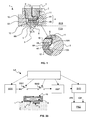
- Figures 1 to 22 show the density and viscosity sensor 1 of the invention.
- Figure 1 is a cross-section view in a sensor 1 which may be any one of the possible sensor embodiments 1A, 1B, 1C, 1D, 1E, 1F and 1G. For clarity purpose, this Figure also shows a magnified portion of a piezoelectric element connection area.
- the density and viscosity sensor 1 comprises a housing 2.
- the sensor comprises a resonating element 3.
- the resonating element 3 which may have various shapes, that will be described in more details hereinafter, is symbolized by a crossed rectangle.
- the housing 2 may further comprise a connector 7 (for clarity purpose, the connector 7 is not shown in details).
- the connector 7 may be a standardized coax connector, a multi-sockets connector or any other connector adapted to a particular application.
- the housing 2 may comprise a peripheral groove (not shown) for receiving an O-ring type sealing (not shown). Any other sealing may be convenient provided that the sealing 15 separates a fluid contacting side FCS from the sensor connecting side SCS.
- the mechanical coupling element 5 constitutes an integral part with the housing.
- the mechanical coupling element 5 may constitute an integral part with the resonating element or may be an additional part coupled to the housing and to the resonating element.
- the function of the mechanical coupling element is to mechanically couple the housing 2 to the resonating element so that vibration can be transmitted through it.
- Another function is to position the resonating element into the fluid to be measured, so that the resonating element is surrounded by said fluid or totally immersed in said fluid.
- the resonating element and the housing integral or not with the coupling element 5 may be assembled together (e.g. by any appropriate welding, gluing, brazing etc. technique).
- the housing 2 comprises a housing interior part defining a chamber 8A.
- the housing 2 in the chamber side, comprises a cavity 8B.
- the cavity 8B defines an area where the housing has a reduced thickness defining a membrane 9 between the chamber 8A and the fluid contacting side FCS.
- the coupling element 5 is positioned onto the membrane 9.
- the coupling element 5 is positioned at sensibly a center point on the membrane.
- the chamber 8A may be filled with a material.
- the material is a vibration absorbing material (e.g. gas, oil, gel, etc). The vibration absorbing material enables to reduce perturbation due to parasitic vibration modes of the housing itself.
- An actuating/detecting element 4 for example a piezoelectric element 4A, 4B is positioned in the cavity 8B.
- the piezoelectric element comprises one disk or a stack of at least two disks (e.g. piezoceramic disks) working in thickness mode and maintained under compression through a compression assembly detailed hereinafter. In the case of an odd number of piezoceramic disk elements, an extremity of the stack should be isolated from the housing.
- the resonating element is coupled to the housing 2 and to the actuating/detecting element 4 by a mechanical coupling element 5 and a supporting part 12
- the mechanical coupling element 5 supports on one side the resonating element 3 and on the other side the supporting part 12.
- the supporting part enables homogenizing mechanical stress at contact point with the actuating/detecting element.
- the supporting part 12 may not be present so that the actuating/detecting element 4 directly contacts the coupling element 5.
- the membrane 9 allows efficient transmission of mechanical signal between the actuating/detecting element 4 and the resonating element 3 while ensuring hermetically separating the fluid contacting side FCS from the cavity 8B.
- the sensor comprises a plug 10 and a screwing plug 11 screwed into the chamber 8A for applying and compressing the piezoelectric element 4 onto the membrane 9.
- the screwing plug 11 may be screwed into the cavity 8B.
- the screwing plug 11 comprises an appropriate hole for the passage of the connecting wire 6 at sensibly the screwing plug center.
- the plug 10 enables application of the piezoelectric element onto the membrane when the screwing plug 11 is screwed.
- the plug 10 lets a passage for the connecting wire 6 from the screwing plug center to the piezoelectric element.
- One side of the piezoelectric element is coupled to the connector (not shown) by the connecting wire 6.
- the other side of the piezoelectric element 4 contacts the membrane 9.
- a supporting part 12 may be positioned between the plug 10 and the support element 5.
- the supporting part 12 constitutes a mechanical interface between the support element 5 and the piezoelectric element 4. Preferably, it may not contact the bottom of the chamber 8A and may slide within the chamber 8A. Thus, the mechanical vibrations are efficiently transferred between the resonating element 3 and the piezoelectric element 4 via the membrane 9 and the supporting part 12.
- the surface ratio between the membrane 9 and the piezoelectric element 4 reduces stress applied to the piezoelectric element by fluid pressure, enabling operation of the sensor at very high pressure.
- a piezoceramic disk comprises a metal layer deposited on both sides of the disk.
- the electrical coupling may be easily obtained by manufacturing all sensor parts except piezoceramic disk stack out of metal and by mechanically securing the sensor assembly.
- the sensor can therefore be operated by applying voltage between the connecting wire 6 and the housing.
- the plug 10 and supporting part 12 can be made of an insulating material and a second wire passed through the plug 10.
- the piezoelectric element 4 comprises two superposed piezoelectric elements 4A and 4B coupled to each other through a thin metal disk 6A connected to the connecting wire 6.
- the first piezoelectric element 4A is also coupled to the plug 10 by a second conductive layer 10A.
- the second piezoelectric element 4B is also coupled to the supporting part 12 by a third conductive layer 12A.
- the first piezoelectric element 4A has an inversed polarization state relatively to the second piezoelectric element 4B.
- the piezoelectric elements are mainly working in compression.
- the two superposed piezoelectric elements 4A and 4B may be excited by an appropriate electrical signal applied between on the one side the first conductive layer 6A, and on the other side the second and third conductive layers 10A, 12A.
- a stack of additional piezoelectric elements e.g. 3, 4, 5, etc... piezoelectric elements
- appropriate polarization and conductive layers connections can be made. Greater is the number of piezoelectric elements, the more signal is delivered by the stack, thus improving measurements that can be made with the sensor.
- the piezoelectric element may have a plain cylindrical shape or a ring shape, namely cylindrical shape that is hollow in its center part.
- the senor further comprises any appropriate means for securing the sensor to a conduit, a tube or a pipe, e.g. flange, screw connection, etc....(not shown in the Figures).
- any appropriate means for securing the sensor to a conduit, a tube or a pipe e.g. flange, screw connection, etc....(not shown in the Figures).
- Such means enables optimally positioning the resonating element within the fluid flow.
- the piezoelectric element and compression assembly enable a reliable sensor behavior at high pressure and temperature (e.g. up to 30Kpsi and 200C) because:
- Figures 2, 3 and 4 are side, perspective and bottom views schematically showing a sensor for measuring density and viscosity of a fluid according to a first embodiment 1A of the invention, respectively.
- the resonating element 3A is under the form of a beam 21, substantially straight, attached at one end to the housing 2 by the mechanical coupling element 5 and comprising, at the other end, a spherical mass 22.
- the beam 21 is made of a wire having a circular cross-section or an elliptical cross-section.
- Figures 5, 6 and 7 are side, perspective and bottom views schematically showing a sensor for measuring density and viscosity of a fluid according to a second embodiment 1B of the invention, respectively.
- the resonating element 3B is under the form of a non-symmetrical U beam comprising a suspended mass at one end. More precisely, the resonating element 3B comprises a first beam portion 31, a second beam portion 32 bent according to a U, a third beam portion 33. The first beam portion 31 and the third beam portion 33 are substantially straight.
- the beam portions are made of a wire having a circular cross-section or an elliptical cross-section.
- a spherical mass 34 is attached at the end of the third beam portion 33.
- Figures 8, 9 and 10 are side, perspective and bottom views schematically showing a sensor for measuring density and viscosity of a fluid according to a third embodiment 1C of the invention, respectively.
- the resonating element 3C is under the form of a beam 41, substantially straight, attached at its center to the housing 2 by the mechanical coupling element 5 and comprising, at the each end, a spherical mass 42 and 43.
- the beam 41 is made of a wire having a circular cross-section or an elliptical cross-section.
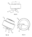
- Figures 11, 12 and 13 are side, perspective and bottom views schematically showing a sensor for measuring density and viscosity of a fluid according to a fourth embodiment 1D of the invention, respectively.
- the resonating element 3D comprises a straight connecting part 51 attached to the housing 2 by the mechanical coupling element 5 and, at one end, a paddle shape beam 52.
- the paddle shape beam 52 forms an angle (e.g. 45° but any other angles may be convenient) relatively to the direction defined by the mechanical coupling element 5 or relatively to the plane defined by the membrane.
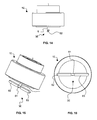
- FIGS 14, 15 and 16 are side, perspective and bottom views schematically showing a sensor for measuring density and viscosity of a fluid according to a fifth embodiment 1E of the invention, respectively.
- the resonating element 3E comprises a straight connecting part 61 attached to the housing 2 by the mechanical coupling element 5 and, at each end, a first 62 and a second 63 paddle shape beam.
- the paddle shape beams 62, 63 form an angle (e.g. 45° but any other angles may be convenient) relatively to the direction defined by the mechanical coupling element 5 or relatively to the plane defined by the membrane. Both paddle shape beams may be oriented according to the same direction.
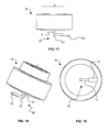
- Figures 17, 18 and 19 are side, perspective and bottom views schematically showing a sensor for measuring density and viscosity of a fluid according to a sixth embodiment 1F of the invention, respectively.
- the resonating element 3F is under the form of a beam 71, substantially straight, attached at one end to the housing 2 by the mechanical coupling element 5 and comprising, around the other end, a plate 72.
- the plate 72 substantially parallel to the plane defined by the membrane, is attached along the beam 71.
- the plate 72 may have a width greater than the beam diameter and may protrude at the end of the beam 72.
- the beam 71 is made of a wire having a circular cross-section or an elliptical cross-section.
- Figures 20, 21 and 22 are side, perspective and bottom views schematically showing a sensor for measuring density and viscosity of a fluid according to a seventh embodiment 1G of the invention, respectively.
- the resonating element 3G is under the form of a beam 81, substantially straight, attached at one end to the housing 2 by the mechanical coupling element 5 and comprising, around the other end, a tube portion 82.
- the tube portion 82 substantially parallel to the plane defined by the membrane, is attached along the beam 81.
- the tube portion 82 may have a diameter greater than the beam diameter.
- the beam 81 is made of a wire having a circular cross-section or an elliptical cross-section.
- the resonating element according to any of the hereinbefore embodiment is aligned with the fluid flow.
- This configuration enables to minimize erosion effect in high velocity particles fluid. It also enables to minimize turbulences induced by the presence of the measuring device and thus the noise on the resonating element.
- the various beams that can be seen in the Figures comprise wires having a circular cross-section.
- the beams may alternatively comprise any wire having an elliptical cross-section or having a parallelepipedic cross-section (for example a rectangular cross-section) or having a triangular cross-section, etc....
- the diameter or the width of the wire may be a few hundreds of micrometers.
- the sensor elements in contact with the fluid e.g. housing 2, membrane 9, coupling element 5, resonating element 3 are made of high strength and high corrosion resistance stainless steel, for example Inconel.
- the resonating element can also be made of material with low density such as sapphire or boron carbon.
- material with low density such as sapphire or boron carbon.
- sapphire or boron carbon improves sensitivity to fluid density.
- the resonating element can be made of specific materials for detecting or measuring chemical species in the fluid.
- Figure 23 schematically illustrates an electronic arrangement EA associated with the density and viscosity sensor of the invention.
- the electronic arrangement may form an integral part with the density and viscosity sensor 1 by integration inside the chamber, or may be externally coupled to an external connector.
- the electronic arrangement may comprise discrete electronic components or may be implemented under the form of an integrated circuit.
- the electronic arrangement EA comprises a controlling circuit LOG, an oscillator SOS, a first switch SW1, a second switch SW2, an amplifier AMP, a detection circuit SYS and a processing circuit PRO.
- the controlling circuit LOG is coupled to the oscillator SOS, the first SW1 and second SW2 switch, the amplifier AMP and the detection circuit SYS.
- the oscillator performs a sensor excitation and detection scheme that will be described in more details hereinafter.
- the controlling circuit LOG closes the first switch SW1 and opens the second switch SW2.
- the oscillator SOS applies an excitation signal to the piezoelectric element 4.
- the excitation signal application causes the piezoelectric element 4 to apply displacements to the coupling element and to the resonating element 3.
- the excitation signal is typically in the range of a few to a few hundred Volts depending of the excitation signals required.
- the excitation could be removed and a reception signal representative of the vibration of the resonating element 3 in the fluid F can be measured.
- the controlling circuit LOG closes the second switch SW2 and opens the first switch SW1.
- the piezoelectric element generates a reception signal representative of the resonating element 3 vibration.
- the detection signal is amplified by the amplifier AMP.
- the detection circuit SYS performs a synchronous detection during a detection phase. It provides to the processing circuit PRO, an actual in-phase response signal IPR and an actual quadrature response signal IQR measured by the sensor 1.
- the processing circuit PRO provides the density and viscosity of the fluid F according to a density and viscosity determination method that will be described in more details hereinafter.
- the second switch SW2 may be omitted or replaced by an appropriate resistance.
- the second switch SW2 basic function is to protect the amplifier AMP because of the difference of magnitude order between the excitation signal and the reception signal.
- the following excitation detection scheme is applied. It is based on the succession of an excitation phase followed by a waiting phase and a detection phase.
- a broadband excitation signal covering the full range of possible resonance frequency, namely F0- ⁇ F to F0+ ⁇ F, according to the range of operation of the sensor is applied through the switch SW1.
- the excitation signal is based on a few periods of a sinus signal which frequency F0 is centered respectively with the useful frequency range, the number of periods defining the width of the useful spectrum.
- the excitation signal stops when crossing zero.
- the decaying signal due to the oscillation amortization of the resonating element in the fluid is measured.
- the detection duration is a compromise between computing complexity and measurement accuracy.
- the order of magnitude is a few hundred of periods.
- the detection signal is amplified and multiplied by two reference signals, at a frequency near F0, and with 90° phase difference. In-phase and quadrature responses are obtained; these two responses are then applied to a low pass filter whose bandwidth is ⁇ F.
- the resulting signals are then used to determine both resonance frequency and quality factor based on the parametrical identification method described in patent application EP05290502.3 incorporated herein by reference.
- the actual responses are compared to calculated response with various resonant frequencies, quality factors and associated correlation coefficient.
- the resonant frequency and the quality factor corresponds to a resonant frequency/quality factor pair which is associated with the higher normalized correlation coefficient sum that can be determined.
- the excitation and detection scheme, together with the density and viscosity calculation according to the invention enables a drastic reduction of the time required to perform resonance frequency and quality factor measurement for un unknown fluid compared to the prior art sensor and method. For example, with the invention measurement and calculation can be performed in less than 1 second.
- the density ⁇ and viscosity ⁇ can be calculated.
- the effective mass of the resonating element 3 is increased by an amount ⁇ m determined by the volume and density of fluid entrained by the moving section. Consequently, this effect is related to fluid density, and a densitometer is provided.
- the resonating element 3 vibrates in the fluid F
- the resonating element drags through the fluid in shear. Consequently, the vibration is dependent upon the resistance to shear of the fluid, and a viscometer is provided.
- a key element of the invention is to replace the evaluation of K through independent measurement of temperature, pressure and the knowledge of beam material properties by using at least two vibration modes of a single vibrating element (or two vibrating beams of same material) having different fitting parameters.
- the correction factor K can be calculated writing that the first ⁇ 1 and second ⁇ 2 density measurements are equal.
- equations [1] to [3] do not need input of temperature nor pressure representing fully compensated density and viscosity predictions based on a robust analytical model.
- the resonating element is a paddle shaped beam having an angle with the axe of the excitation movement to allow excitation/detection of vibration modes in the plane of the paddle and perpendicularly to this plane.
- the first resonance mode is characterized by a first resonant frequency F 1 and a first quality factor Q 1 .
- This mode corresponds to the paddle oscillating perpendicularly to its plane. In this mode, the paddle moves a large volume of fluid. Consequently, the first resonant frequency F 1 is highly sensitive to fluid density.
- the second resonance mode is characterized by a second resonant frequency F 2 and a second quality factor Q 2 . This mode corresponds to the paddle oscillating within its plane. In this mode, the paddle mostly shears the surrounding fluid. Consequently, the second resonant frequency F 2 is quite insensitive to fluid density while being sensitive to the damping effect.
- actuating/detecting element under the form of a piezoelectric element has been described. However, it will be apparent that this is an example of actuating/detecting element and that any electrical/mechanical vibration converting arrangement, e.g. a electrical motor, may be employed.
- each beam is shown in the Figures as sensibly parallel to the area of the sensor housing contacting the fluid to be measured.
- each beam may be positioned relatively to the area of the sensor housing contacting the fluid to be measured according to any angle (for example 10°, 30°, 45°, etc.).
- connection of the density and viscosity sensor to a conduit in which flow a fluid to be measured is not limited to the example hereinbefore described. It will be apparent for a person skilled in the art that others connections are possible depending of the application of the density and viscosity sensor.
- a plurality of sensors may be positioned in close proximity, for example two sensors may be positioned along the flow line for redundancy measurement purposes.
- connection used in hereinbefore is not limited to a mechanical/electrical connection. It will be apparent for a person skilled in the art that a wireless connector may be used to transmit measurements from the sensor to any system requiring such measurements.
- the invention finds application in various industry domains, for example the oilfield industry as density and viscosity sensor in down-hole tool, the chemical industry (plastic manufacturing, cosmetic preparation manufacturing), food industry, etc.... It may also be employed in aeronautical applications, for example for detecting the formation of ice on e.g. plane wing by measuring the shift of resonance frequency due to the ice added mass on the resonating element.
Landscapes
- Immunology (AREA)
- Pathology (AREA)
- Life Sciences & Earth Sciences (AREA)
- Chemical & Material Sciences (AREA)
- Analytical Chemistry (AREA)
- Biochemistry (AREA)
- Health & Medical Sciences (AREA)
- General Health & Medical Sciences (AREA)
- Physics & Mathematics (AREA)
- General Physics & Mathematics (AREA)
- Measuring Fluid Pressure (AREA)
- Investigating Or Analyzing Materials By The Use Of Ultrasonic Waves (AREA)
- Measurement Of Mechanical Vibrations Or Ultrasonic Waves (AREA)
- Detergent Compositions (AREA)
- Investigating Or Analyzing Materials Using Thermal Means (AREA)
- Liquid Developers In Electrophotography (AREA)
Priority Applications (8)
| Application Number | Priority Date | Filing Date | Title |
|---|---|---|---|
| EP05292827A EP1804048B1 (fr) | 2005-12-30 | 2005-12-30 | Capteur de densité et de viscosité |
| AT05292827T ATE467829T1 (de) | 2005-12-30 | 2005-12-30 | Dichte- und viskositätssensor |
| DK05292827.2T DK1804048T3 (da) | 2005-12-30 | 2005-12-30 | Densitets- og viskositetssensor |
| DE602005021236T DE602005021236D1 (de) | 2005-12-30 | 2005-12-30 | Dichte- und Viskositätssensor |
| CN2006800499672A CN101351696B (zh) | 2005-12-30 | 2006-12-27 | 密度和粘度传感器 |
| US12/097,901 US7874199B2 (en) | 2005-12-30 | 2006-12-27 | Density and viscosity sensor |
| CA2639850A CA2639850C (fr) | 2005-12-30 | 2006-12-27 | Capteur de densite et de viscosite |
| PCT/EP2006/012652 WO2007077038A1 (fr) | 2005-12-30 | 2006-12-27 | Capteur de densité et de viscosité |
Applications Claiming Priority (1)
| Application Number | Priority Date | Filing Date | Title |
|---|---|---|---|
| EP05292827A EP1804048B1 (fr) | 2005-12-30 | 2005-12-30 | Capteur de densité et de viscosité |
Publications (2)
| Publication Number | Publication Date |
|---|---|
| EP1804048A1 true EP1804048A1 (fr) | 2007-07-04 |
| EP1804048B1 EP1804048B1 (fr) | 2010-05-12 |
Family
ID=36051565
Family Applications (1)
| Application Number | Title | Priority Date | Filing Date |
|---|---|---|---|
| EP05292827A Expired - Lifetime EP1804048B1 (fr) | 2005-12-30 | 2005-12-30 | Capteur de densité et de viscosité |
Country Status (8)
| Country | Link |
|---|---|
| US (1) | US7874199B2 (fr) |
| EP (1) | EP1804048B1 (fr) |
| CN (1) | CN101351696B (fr) |
| AT (1) | ATE467829T1 (fr) |
| CA (1) | CA2639850C (fr) |
| DE (1) | DE602005021236D1 (fr) |
| DK (1) | DK1804048T3 (fr) |
| WO (1) | WO2007077038A1 (fr) |
Cited By (13)
| Publication number | Priority date | Publication date | Assignee | Title |
|---|---|---|---|---|
| GB2484454A (en) * | 2010-09-03 | 2012-04-18 | Cambridge Entpr Ltd | Sensing a property of a fluid using two resonant elements |
| WO2012047983A3 (fr) * | 2010-10-07 | 2012-06-14 | Baker Hughes Incorporated | Procédé et appareil pour estimer une viscosité et une densité de fond de trou à l'aide d'un élément électriquement conducteur vibrant relâché |
| WO2012047995A3 (fr) * | 2010-10-07 | 2012-06-14 | Baker Hughes Incorporated | Viscosité de vibration de torsion et capteur de densité pour applications de fond de trou |
| WO2012025840A3 (fr) * | 2010-08-26 | 2013-04-25 | Schlumberger Canada Limited | Appareil et procédé pour équilibre de phase à détection in situ |
| US8689614B2 (en) | 2007-08-24 | 2014-04-08 | Highland Biosciences Limited | Apparatus and method for determining the results of assays |
| US8845968B2 (en) | 2006-12-28 | 2014-09-30 | Highland Biosciences Limited | Biosensor |
| EP2846159A1 (fr) * | 2013-09-06 | 2015-03-11 | Services Pétroliers Schlumberger | Capteur fluidique avec actuateur piézoélectrique et son procédé de fabrication |
| US9243493B2 (en) | 2008-06-11 | 2016-01-26 | Schlumberger Technology Corporation | Fluid density from downhole optical measurements |
| EP3147645A1 (fr) | 2015-09-22 | 2017-03-29 | Avenisense | Capteur de densité et procédé de fabrication d'un capteur de densité |
| EP3214424A1 (fr) * | 2016-03-04 | 2017-09-06 | Buira Nunez, Ernest | Dispositif de détection, système et procédé permettant de mesurer les propriétés d'un fluide comprenant la viscosité et/ou densité |
| WO2018197902A1 (fr) * | 2017-04-27 | 2018-11-01 | Hydramotion Limited | Mesure de propriétés de fluides à contrainte de rendement en écoulement |
| WO2019068553A1 (fr) * | 2017-10-05 | 2019-04-11 | Endress+Hauser Flowtec Ag | Transformateur de mesure pour système de mesure à vibrations et système de mesure à vibrations réalisé au moyen dudit transformateur |
| US12461269B2 (en) | 2022-09-15 | 2025-11-04 | Schlumberger Technology Corporation | Fluid density and viscosity measurement tool with noise cancellation |
Families Citing this family (57)
| Publication number | Priority date | Publication date | Assignee | Title |
|---|---|---|---|---|
| DE102006033819A1 (de) * | 2006-07-19 | 2008-01-24 | Endress + Hauser Gmbh + Co. Kg | Vorrichtung zur Bestimmung und/oder Überwachung einer Prozessgröße eines Mediums |
| DE102007008669A1 (de) * | 2007-02-20 | 2008-08-21 | Endress + Hauser Gmbh + Co. Kg | Verfahren zur Bestimmung und/oder Überwachung einer Prozessgröße eines Mediums und entsprechende Vorrichtung |
| JP5266438B2 (ja) * | 2007-03-19 | 2013-08-21 | コンティ テミック マイクロエレクトロニック ゲゼルシャフト ミット ベシュレンクテル ハフツング | センサ装置 |
| US7784330B2 (en) | 2007-10-05 | 2010-08-31 | Schlumberger Technology Corporation | Viscosity measurement |
| EP2313610B1 (fr) * | 2008-07-14 | 2012-10-17 | Schlumberger Technology B.V. | Instrument et procédé d évaluation de formations |
| WO2010009411A2 (fr) | 2008-07-17 | 2010-01-21 | Schlumberger Canada Limited | Détermination d'un glucide en présence d'électrons et d'ionisation chimique |
| CN101477020B (zh) * | 2009-01-12 | 2011-06-08 | 北京博奇电力科技有限公司 | 测量脱硫吸收塔浆液密度的方法 |
| US9274248B2 (en) * | 2009-01-21 | 2016-03-01 | Schlumberger Technology Corporation | Downhole mass spectrometry |
| US8596384B2 (en) * | 2009-02-06 | 2013-12-03 | Schlumberger Technology Corporation | Reducing differential sticking during sampling |
| US8751172B2 (en) * | 2009-06-29 | 2014-06-10 | Rochester Institute Of Technology | Microelectromechanical viscosity measurement devices and methods thereof |
| US8109334B2 (en) | 2009-07-13 | 2012-02-07 | Schlumberger Technology Corporation | Sampling and evaluation of subterranean formation fluid |
| EP2462425A4 (fr) * | 2009-08-03 | 2017-04-05 | Ultimo Measurement, LLC | Procédés et appareil pour la mesure des propriétés physiques de matériaux à écoulement libre dans des cuves |
| WO2011044028A2 (fr) | 2009-10-05 | 2011-04-14 | Schlumberger Canada Limited | Opération sur champ pétrolifère à l'aide d'un train de forage |
| WO2011043890A2 (fr) | 2009-10-05 | 2011-04-14 | Schlumberger Canada Limited | Test de formation |
| WO2011044070A2 (fr) | 2009-10-06 | 2011-04-14 | Schlumberger Canada Limited | Planification et surveillance d'essai des couches |
| US8146655B2 (en) * | 2009-10-13 | 2012-04-03 | Schlumberger Technology Corporation | Methods and apparatus for downhole characterization of emulsion stability |
| AU2010349753C1 (en) | 2010-03-29 | 2015-02-19 | Halliburton Energy Services, Inc. | Apparatus and methods of determining fluid viscosity |
| US8763696B2 (en) | 2010-04-27 | 2014-07-01 | Sylvain Bedouet | Formation testing |
| US8850879B2 (en) | 2011-03-16 | 2014-10-07 | Baker Hughes Incorporated | Sample channel for a sensor for measuring fluid properties |
| US8970093B2 (en) | 2011-03-16 | 2015-03-03 | Baker Hughes Incorporated | Piezoelectric transducer for measuring fluid properties |
| US9275009B2 (en) | 2011-09-02 | 2016-03-01 | Schlumberger Technology Corporation | Calibration and consistency check of variable volume systems |
| US8905130B2 (en) * | 2011-09-20 | 2014-12-09 | Schlumberger Technology Corporation | Fluid sample cleanup |
| US9249660B2 (en) | 2011-11-28 | 2016-02-02 | Schlumberger Technology Corporation | Formation fluid sampling |
| DE102011088304B4 (de) * | 2011-12-12 | 2023-09-21 | Endress+Hauser SE+Co. KG | Vorrichtung zur Bestimmung und/oder Überwachung mindestens einer Prozessgröße |
| US9038443B1 (en) * | 2011-12-14 | 2015-05-26 | Maria Esther Pace | Microfabricated resonant fluid density and viscosity sensor |
| DE102011089808A1 (de) | 2011-12-23 | 2013-06-27 | Endress + Hauser Flowtec Ag | Verfahren bzw. Meßsystem zum Ermitteln einer Dichte eines Fluids |
| US9903830B2 (en) | 2011-12-29 | 2018-02-27 | Lifescan Scotland Limited | Accurate analyte measurements for electrochemical test strip based on sensed physical characteristic(s) of the sample containing the analyte |
| JP2015503767A (ja) | 2012-01-16 | 2015-02-02 | エイブラム サイエンティフィック,インコーポレーテッド | 流体の物理的特性を測定するための方法、デバイス、およびシステム |
| WO2013110343A1 (fr) * | 2012-01-27 | 2013-08-01 | Abb Technology Ag | Procédé et dispositif acoustiques pour mesurer la densité ou la viscosité d'un fluide |
| EP2650668A1 (fr) | 2012-04-12 | 2013-10-16 | Openfield | Capteur de densité et de viscosité et procédé de mesure |
| CN105209901B (zh) | 2013-02-06 | 2018-08-24 | 乌尔蒂莫测量有限责任公司 | 用于测量容器中自由流动物质的物理性质的非侵入性方法 |
| US9835578B2 (en) | 2013-06-27 | 2017-12-05 | Lifescan Scotland Limited | Temperature compensation for an analyte measurement determined from a specified sampling time derived from a sensed physical characteristic of the sample containing the analyte |
| US9435762B2 (en) | 2013-06-27 | 2016-09-06 | Lifescan Scotland Limited | Fill error trap for an analyte measurement determined from a specified sampling time derived from a sensed physical characteristic of the sample containing the analyte |
| US9435764B2 (en) | 2013-06-27 | 2016-09-06 | Lifescan Scotland Limited | Transient signal error trap for an analyte measurement determined from a specified sampling time derived from a sensed physical characteristic of the sample containing the analyte |
| US9243276B2 (en) | 2013-08-29 | 2016-01-26 | Lifescan Scotland Limited | Method and system to determine hematocrit-insensitive glucose values in a fluid sample |
| US9459231B2 (en) | 2013-08-29 | 2016-10-04 | Lifescan Scotland Limited | Method and system to determine erroneous measurement signals during a test measurement sequence |
| US9828621B2 (en) | 2013-09-10 | 2017-11-28 | Lifescan Scotland Limited | Anomalous signal error trap for an analyte measurement determined from a specified sampling time derived from a sensed physical characteristic of the sample containing the analyte |
| US9816848B2 (en) | 2014-01-23 | 2017-11-14 | Ultimo Measurement Llc | Method and apparatus for non-invasively measuring physical properties of materials in a conduit |
| WO2016043722A1 (fr) | 2014-09-16 | 2016-03-24 | Halliburton Energy Services, Inc. | Capteur viscosimètre de fluide de formation de fond de trou |
| US20160091451A1 (en) | 2014-09-25 | 2016-03-31 | Lifescan Scotland Limited | Accurate analyte measurements for electrochemical test strip to determine analyte measurement time based on measured temperature, physical characteristic and estimated analyte value |
| US20160091450A1 (en) | 2014-09-25 | 2016-03-31 | Lifescan Scotland Limited | Accurate analyte measurements for electrochemical test strip to determine analyte measurement time based on measured temperature, physical characteristic and estimated analyte value and their temperature compensated values |
| BR112017004177A2 (pt) | 2014-10-30 | 2017-12-12 | Halliburton Energy Services Inc | sistema de pacote de sensor de fundo de poço, e, métodos para determinar densidade e viscosidade de um fluido de formação e para detectar uma ou mais propriedades de um fluido de fundo de poço. |
| US10295449B2 (en) | 2014-12-17 | 2019-05-21 | Schlumberger Technology Corporation | Determining resonance frequency and quality factor |
| US10107784B2 (en) | 2014-12-29 | 2018-10-23 | Concentric Meter Corporation | Electromagnetic transducer |
| US10126266B2 (en) | 2014-12-29 | 2018-11-13 | Concentric Meter Corporation | Fluid parameter sensor and meter |
| US9752911B2 (en) | 2014-12-29 | 2017-09-05 | Concentric Meter Corporation | Fluid parameter sensor and meter |
| WO2016133542A1 (fr) | 2015-02-20 | 2016-08-25 | Halliburton Energy Services, Inc. | Détermination de la densité et de la viscosité d'un fluide au moyen d'un capteur de densité et de viscosité à force électromagnétique appliquée sans contact |
| CN104634702B (zh) * | 2015-03-06 | 2018-05-22 | 合肥工业大学 | 一种压电扭振式粘度、密度及介电常数在线同时测量探头 |
| CN105987859B (zh) * | 2016-04-22 | 2018-07-17 | 纳智源科技(唐山)有限责任公司 | 流体密度的测量装置及方法 |
| US10689980B2 (en) | 2016-05-13 | 2020-06-23 | Schlumberger Technology Corporation | Downhole characterization of fluid compressibility |
| EP3258239A1 (fr) * | 2016-06-13 | 2017-12-20 | INL - International Iberian Nanotechnology Laboratory | Procédé de validation d'un résonateur |
| RU180588U1 (ru) * | 2017-11-14 | 2018-06-19 | Федеральное государственное казенное военное образовательное учреждение высшего профессионального образования "Военная академия материально-технического обеспечения имени генерала армии А.В. Хрулёва" Министерства обороны Российской Федерации | Усовершенствованный вибротермодатчик камертонного типа |
| RU188748U1 (ru) * | 2018-12-28 | 2019-04-23 | Федеральное государственное казенное военное образовательное учреждение высшего профессионального образования "Военная академия материально-технического обеспечения имени генерала армии А.В. Хрулёва" Министерства обороны Российской Федерации | Вискозиметрический датчик для комплекса автоматизированной диагностики дизельных двигателей |
| US12584930B2 (en) | 2019-02-04 | 2026-03-24 | Abram Scientific, Inc. | Fluid property measurement devices and methods |
| RU2722470C1 (ru) * | 2020-01-31 | 2020-06-01 | Александр Петрович Демченко | Датчик вибрационного плотномера (варианты) |
| KR102840490B1 (ko) * | 2020-07-08 | 2025-07-30 | 마이크로 모우션, 인코포레이티드 | 진동계 q를 계산하기 위한 방법 및 장치 |
| CN112630104B (zh) * | 2020-12-17 | 2025-05-02 | 广州机械科学研究院有限公司 | 一种黏度传感器装置及黏度测量方法 |
Citations (5)
| Publication number | Priority date | Publication date | Assignee | Title |
|---|---|---|---|---|
| US5323638A (en) * | 1989-10-05 | 1994-06-28 | Gec-Marconi Limited | Sensor apparatus |
| US6389891B1 (en) | 2000-03-24 | 2002-05-21 | Endress + Hauser Gmbh + Co. | Method and apparatus for establishing and/or monitoring the filling level of a medium in a container |
| US6494079B1 (en) * | 2001-03-07 | 2002-12-17 | Symyx Technologies, Inc. | Method and apparatus for characterizing materials by using a mechanical resonator |
| WO2005114138A2 (fr) * | 2004-04-22 | 2005-12-01 | Biode, Inc. | Mesure de la densite et de la viscoelasticite au moyen d'un capteur d'onde acoustique unique |
| EP1698880A1 (fr) | 2005-03-04 | 2006-09-06 | Services Petroliers Schlumberger | capteur de viscosité et densité |
Family Cites Families (8)
| Publication number | Priority date | Publication date | Assignee | Title |
|---|---|---|---|---|
| GB2067756B (en) * | 1980-01-15 | 1983-11-16 | Marconi Co Ltd | Liquid level measurement |
| DE3336991A1 (de) * | 1983-10-11 | 1985-05-02 | Endress U. Hauser Gmbh U. Co, 7867 Maulburg | Vorrichtung zur feststellung und/oder ueberwachung eines vorbestimmten fuellstands in einem behaelter |
| GB8705757D0 (en) | 1987-03-11 | 1987-04-15 | Schlumberger Electronics Uk | Fluid transducer |
| DE50106202D1 (de) * | 2000-03-08 | 2005-06-16 | Endress & Hauser Gmbh & Co Kg | Vorrichtung zur feststellung und/oder überwachung eines vorbestimmten füllstandes in einem behälter |
| DE10057974A1 (de) * | 2000-11-22 | 2002-05-23 | Endress Hauser Gmbh Co | Verfahren und Vorrichtung zur Feststellung und/oder Überwachung des Füllstands eines Mediums in einem Behälter bzw. zur Ermittlung der Dichte eines Mediums in einem Behälter |
| JP2004526251A (ja) * | 2001-03-28 | 2004-08-26 | エンドレス ウント ハウザー ゲーエムベーハー ウント コンパニー コマンディートゲゼルシャフト | 容器内の所定の充填レベルを決定及び/又は監視する装置 |
| DE10129556A1 (de) * | 2001-06-19 | 2003-01-09 | Endress & Hauser Gmbh & Co Kg | Vorrichtung zur Bestimmung und/oder Überwachung des Füllstandes eines Mediums in einem Behälter |
| ATE546720T1 (de) | 2003-03-21 | 2012-03-15 | MEAS France | Resonator-sensor-einheit |
-
2005
- 2005-12-30 AT AT05292827T patent/ATE467829T1/de not_active IP Right Cessation
- 2005-12-30 DK DK05292827.2T patent/DK1804048T3/da active
- 2005-12-30 DE DE602005021236T patent/DE602005021236D1/de not_active Expired - Lifetime
- 2005-12-30 EP EP05292827A patent/EP1804048B1/fr not_active Expired - Lifetime
-
2006
- 2006-12-27 CN CN2006800499672A patent/CN101351696B/zh not_active Expired - Fee Related
- 2006-12-27 CA CA2639850A patent/CA2639850C/fr not_active Expired - Fee Related
- 2006-12-27 WO PCT/EP2006/012652 patent/WO2007077038A1/fr not_active Ceased
- 2006-12-27 US US12/097,901 patent/US7874199B2/en active Active
Patent Citations (5)
| Publication number | Priority date | Publication date | Assignee | Title |
|---|---|---|---|---|
| US5323638A (en) * | 1989-10-05 | 1994-06-28 | Gec-Marconi Limited | Sensor apparatus |
| US6389891B1 (en) | 2000-03-24 | 2002-05-21 | Endress + Hauser Gmbh + Co. | Method and apparatus for establishing and/or monitoring the filling level of a medium in a container |
| US6494079B1 (en) * | 2001-03-07 | 2002-12-17 | Symyx Technologies, Inc. | Method and apparatus for characterizing materials by using a mechanical resonator |
| WO2005114138A2 (fr) * | 2004-04-22 | 2005-12-01 | Biode, Inc. | Mesure de la densite et de la viscoelasticite au moyen d'un capteur d'onde acoustique unique |
| EP1698880A1 (fr) | 2005-03-04 | 2006-09-06 | Services Petroliers Schlumberger | capteur de viscosité et densité |
Cited By (22)
| Publication number | Priority date | Publication date | Assignee | Title |
|---|---|---|---|---|
| US9034264B2 (en) | 2006-12-28 | 2015-05-19 | Highland Biosciences Limited | Biosensor |
| US8845968B2 (en) | 2006-12-28 | 2014-09-30 | Highland Biosciences Limited | Biosensor |
| US8689614B2 (en) | 2007-08-24 | 2014-04-08 | Highland Biosciences Limited | Apparatus and method for determining the results of assays |
| US9243493B2 (en) | 2008-06-11 | 2016-01-26 | Schlumberger Technology Corporation | Fluid density from downhole optical measurements |
| AU2011294831B2 (en) * | 2010-08-26 | 2014-10-02 | Schlumberger Technology B.V. | Apparatus and method for phase equilibrium with in-situ sensing |
| WO2012025840A3 (fr) * | 2010-08-26 | 2013-04-25 | Schlumberger Canada Limited | Appareil et procédé pour équilibre de phase à détection in situ |
| US9291585B2 (en) | 2010-08-26 | 2016-03-22 | Schlumberger Technology Corporation | Apparatus and method for phase equilibrium with in-situ sensing |
| GB2484454B (en) * | 2010-09-03 | 2014-01-08 | Cambridge Entpr Ltd | Sensor and method for sensing a property of a fluid |
| GB2484454A (en) * | 2010-09-03 | 2012-04-18 | Cambridge Entpr Ltd | Sensing a property of a fluid using two resonant elements |
| GB2498128A (en) * | 2010-10-07 | 2013-07-03 | Baker Hughes Inc | A method and apparatus for estimating viscosity and density downhole using a relaxed vibrating electrically conductive element |
| GB2497446A (en) * | 2010-10-07 | 2013-06-12 | Baker Hughes Inc | Torsionally vibrating viscosity and density sensor for downhole applications |
| WO2012047995A3 (fr) * | 2010-10-07 | 2012-06-14 | Baker Hughes Incorporated | Viscosité de vibration de torsion et capteur de densité pour applications de fond de trou |
| WO2012047983A3 (fr) * | 2010-10-07 | 2012-06-14 | Baker Hughes Incorporated | Procédé et appareil pour estimer une viscosité et une densité de fond de trou à l'aide d'un élément électriquement conducteur vibrant relâché |
| EP2846159A1 (fr) * | 2013-09-06 | 2015-03-11 | Services Pétroliers Schlumberger | Capteur fluidique avec actuateur piézoélectrique et son procédé de fabrication |
| EP3147645A1 (fr) | 2015-09-22 | 2017-03-29 | Avenisense | Capteur de densité et procédé de fabrication d'un capteur de densité |
| WO2017050875A1 (fr) | 2015-09-22 | 2017-03-30 | Avenisense | Capteur de densité et son procédé de fabrication |
| EP3214424A1 (fr) * | 2016-03-04 | 2017-09-06 | Buira Nunez, Ernest | Dispositif de détection, système et procédé permettant de mesurer les propriétés d'un fluide comprenant la viscosité et/ou densité |
| WO2018197902A1 (fr) * | 2017-04-27 | 2018-11-01 | Hydramotion Limited | Mesure de propriétés de fluides à contrainte de rendement en écoulement |
| EP3615912A1 (fr) * | 2017-04-27 | 2020-03-04 | Hydramotion Limited | Mesure de propriétés de fluides à contrainte de rendement en écoulement |
| WO2019068553A1 (fr) * | 2017-10-05 | 2019-04-11 | Endress+Hauser Flowtec Ag | Transformateur de mesure pour système de mesure à vibrations et système de mesure à vibrations réalisé au moyen dudit transformateur |
| US11530967B2 (en) | 2017-10-05 | 2022-12-20 | Endress+Hauser Flowtec Ag | Transducer for a vibronic measuring system and vibronic measuring system formed therewith |
| US12461269B2 (en) | 2022-09-15 | 2025-11-04 | Schlumberger Technology Corporation | Fluid density and viscosity measurement tool with noise cancellation |
Also Published As
| Publication number | Publication date |
|---|---|
| DK1804048T3 (da) | 2010-09-06 |
| CN101351696A (zh) | 2009-01-21 |
| US7874199B2 (en) | 2011-01-25 |
| DE602005021236D1 (de) | 2010-06-24 |
| US20080257036A1 (en) | 2008-10-23 |
| CN101351696B (zh) | 2012-07-18 |
| WO2007077038A1 (fr) | 2007-07-12 |
| ATE467829T1 (de) | 2010-05-15 |
| EP1804048B1 (fr) | 2010-05-12 |
| CA2639850C (fr) | 2015-10-20 |
| WO2007077038A8 (fr) | 2008-10-23 |
| CA2639850A1 (fr) | 2007-07-12 |
Similar Documents
| Publication | Publication Date | Title |
|---|---|---|
| EP1804048B1 (fr) | Capteur de densité et de viscosité | |
| EP1698880B1 (fr) | capteur de viscosité et densité | |
| EP2359115B1 (fr) | Procédé et appareil pour la mesure de pression à l'aide d'un cristal de quartz | |
| CN101517382B (zh) | 用于确定和/或监控介质的过程变量的系统 | |
| EP0282251A2 (fr) | Transducteur pour liquides | |
| JP2009258085A (ja) | 圧力センサおよびその製造方法 | |
| CN101198865A (zh) | 无线声学滤油器传感器 | |
| Matsiev | Application of flexural mechanical resonators to high throughput liquid characterization | |
| US20260049916A1 (en) | Method and apparatus for calculating a vibratory meter q | |
| Najmzadeh et al. | A silicon straight tube fluid density sensor | |
| KR100741262B1 (ko) | 마이크로 점도계 | |
| EP3353526B1 (fr) | Capteur de densité et son procédé de fabrication | |
| EP3894829B1 (fr) | Viscosimètre vibratoire plan, élément de viscosimètre et procédé associé | |
| EP4098999B1 (fr) | Capteur de densitomètre à vibrations | |
| WO2001061312A1 (fr) | Procede de determination de la viscosite | |
| Kumar et al. | Laterally excited bulk acoustic wave resonator (XBAR)-based sensor for real-time liquid density measurement | |
| RU2806622C1 (ru) | Способ и устройство для вычисления показателя добротности q вибрационного измерительного устройства | |
| JP2013156197A (ja) | 圧力センサー、圧力計、電子機器 | |
| Welham | A Silicon Micromachined Lateral Resonant Strain Gauge Pressure Sensor | |
| Lee et al. | Study on the development of the Flexural Plate Wave (FPW) accelerometer for the continuous damping control system of an automobile | |
| JP2011027523A (ja) | 圧力センサー |
Legal Events
| Date | Code | Title | Description |
|---|---|---|---|
| PUAI | Public reference made under article 153(3) epc to a published international application that has entered the european phase |
Free format text: ORIGINAL CODE: 0009012 |
|
| AK | Designated contracting states |
Kind code of ref document: A1 Designated state(s): AT BE BG CH CY CZ DE DK EE ES FI FR GB GR HU IE IS IT LI LT LU LV MC NL PL PT RO SE SI SK TR |
|
| AX | Request for extension of the european patent |
Extension state: AL BA HR MK YU |
|
| 17P | Request for examination filed |
Effective date: 20071213 |
|
| 17Q | First examination report despatched |
Effective date: 20080118 |
|
| AKX | Designation fees paid |
Designated state(s): AT BE BG CH CY CZ DE DK EE ES FI FR GB GR HU IE IS IT LI LT LU LV MC NL PL PT RO SE SI SK TR |
|
| GRAP | Despatch of communication of intention to grant a patent |
Free format text: ORIGINAL CODE: EPIDOSNIGR1 |
|
| GRAS | Grant fee paid |
Free format text: ORIGINAL CODE: EPIDOSNIGR3 |
|
| GRAA | (expected) grant |
Free format text: ORIGINAL CODE: 0009210 |
|
| AK | Designated contracting states |
Kind code of ref document: B1 Designated state(s): AT BE BG CH CY CZ DE DK EE ES FI FR GB GR HU IE IS IT LI LT LU LV MC NL PL PT RO SE SI SK TR |
|
| REG | Reference to a national code |
Ref country code: GB Ref legal event code: FG4D |
|
| REG | Reference to a national code |
Ref country code: CH Ref legal event code: EP |
|
| REG | Reference to a national code |
Ref country code: IE Ref legal event code: FG4D |
|
| REF | Corresponds to: |
Ref document number: 602005021236 Country of ref document: DE Date of ref document: 20100624 Kind code of ref document: P |
|
| REG | Reference to a national code |
Ref country code: NL Ref legal event code: VDEP Effective date: 20100512 |
|
| REG | Reference to a national code |
Ref country code: CH Ref legal event code: PFA Owner name: PRAD RESEARCH AND DEVELOPMENT LIMITED A BRITISH V Free format text: PRAD RESEARCH AND DEVELOPMENT N.V.#DE RUYTERKADE 62#WILLEMSTAD, CURACAO (AN) -TRANSFER TO- PRAD RESEARCH AND DEVELOPMENT LIMITED A BRITISH VIRGIN ISLANDS CORPORATION#P.O. BOX 71-CRAIGMUIR CHAMBERS ROAD TOWN TORTOLA#BRITISH VIRGIN ISLANDS (VG) Ref country code: CH Ref legal event code: NV Representative=s name: BOVARD AG PATENTANWAELTE |
|
| REG | Reference to a national code |
Ref country code: DK Ref legal event code: T3 |
|
| LTIE | Lt: invalidation of european patent or patent extension |
Effective date: 20100512 |
|
| PG25 | Lapsed in a contracting state [announced via postgrant information from national office to epo] |
Ref country code: LT Free format text: LAPSE BECAUSE OF FAILURE TO SUBMIT A TRANSLATION OF THE DESCRIPTION OR TO PAY THE FEE WITHIN THE PRESCRIBED TIME-LIMIT Effective date: 20100512 Ref country code: ES Free format text: LAPSE BECAUSE OF FAILURE TO SUBMIT A TRANSLATION OF THE DESCRIPTION OR TO PAY THE FEE WITHIN THE PRESCRIBED TIME-LIMIT Effective date: 20100823 Ref country code: NL Free format text: LAPSE BECAUSE OF FAILURE TO SUBMIT A TRANSLATION OF THE DESCRIPTION OR TO PAY THE FEE WITHIN THE PRESCRIBED TIME-LIMIT Effective date: 20100512 Ref country code: SE Free format text: LAPSE BECAUSE OF FAILURE TO SUBMIT A TRANSLATION OF THE DESCRIPTION OR TO PAY THE FEE WITHIN THE PRESCRIBED TIME-LIMIT Effective date: 20100512 |
|
| PG25 | Lapsed in a contracting state [announced via postgrant information from national office to epo] |
Ref country code: SI Free format text: LAPSE BECAUSE OF FAILURE TO SUBMIT A TRANSLATION OF THE DESCRIPTION OR TO PAY THE FEE WITHIN THE PRESCRIBED TIME-LIMIT Effective date: 20100512 Ref country code: FI Free format text: LAPSE BECAUSE OF FAILURE TO SUBMIT A TRANSLATION OF THE DESCRIPTION OR TO PAY THE FEE WITHIN THE PRESCRIBED TIME-LIMIT Effective date: 20100512 Ref country code: IS Free format text: LAPSE BECAUSE OF FAILURE TO SUBMIT A TRANSLATION OF THE DESCRIPTION OR TO PAY THE FEE WITHIN THE PRESCRIBED TIME-LIMIT Effective date: 20100912 Ref country code: LV Free format text: LAPSE BECAUSE OF FAILURE TO SUBMIT A TRANSLATION OF THE DESCRIPTION OR TO PAY THE FEE WITHIN THE PRESCRIBED TIME-LIMIT Effective date: 20100512 Ref country code: AT Free format text: LAPSE BECAUSE OF FAILURE TO SUBMIT A TRANSLATION OF THE DESCRIPTION OR TO PAY THE FEE WITHIN THE PRESCRIBED TIME-LIMIT Effective date: 20100512 |
|
| PG25 | Lapsed in a contracting state [announced via postgrant information from national office to epo] |
Ref country code: CY Free format text: LAPSE BECAUSE OF FAILURE TO SUBMIT A TRANSLATION OF THE DESCRIPTION OR TO PAY THE FEE WITHIN THE PRESCRIBED TIME-LIMIT Effective date: 20100512 Ref country code: PL Free format text: LAPSE BECAUSE OF FAILURE TO SUBMIT A TRANSLATION OF THE DESCRIPTION OR TO PAY THE FEE WITHIN THE PRESCRIBED TIME-LIMIT Effective date: 20100512 Ref country code: GR Free format text: LAPSE BECAUSE OF FAILURE TO SUBMIT A TRANSLATION OF THE DESCRIPTION OR TO PAY THE FEE WITHIN THE PRESCRIBED TIME-LIMIT Effective date: 20100813 |
|
| PG25 | Lapsed in a contracting state [announced via postgrant information from national office to epo] |
Ref country code: PT Free format text: LAPSE BECAUSE OF FAILURE TO SUBMIT A TRANSLATION OF THE DESCRIPTION OR TO PAY THE FEE WITHIN THE PRESCRIBED TIME-LIMIT Effective date: 20100913 Ref country code: EE Free format text: LAPSE BECAUSE OF FAILURE TO SUBMIT A TRANSLATION OF THE DESCRIPTION OR TO PAY THE FEE WITHIN THE PRESCRIBED TIME-LIMIT Effective date: 20100512 |
|
| PG25 | Lapsed in a contracting state [announced via postgrant information from national office to epo] |
Ref country code: SK Free format text: LAPSE BECAUSE OF FAILURE TO SUBMIT A TRANSLATION OF THE DESCRIPTION OR TO PAY THE FEE WITHIN THE PRESCRIBED TIME-LIMIT Effective date: 20100512 Ref country code: RO Free format text: LAPSE BECAUSE OF FAILURE TO SUBMIT A TRANSLATION OF THE DESCRIPTION OR TO PAY THE FEE WITHIN THE PRESCRIBED TIME-LIMIT Effective date: 20100512 Ref country code: CZ Free format text: LAPSE BECAUSE OF FAILURE TO SUBMIT A TRANSLATION OF THE DESCRIPTION OR TO PAY THE FEE WITHIN THE PRESCRIBED TIME-LIMIT Effective date: 20100512 Ref country code: BE Free format text: LAPSE BECAUSE OF FAILURE TO SUBMIT A TRANSLATION OF THE DESCRIPTION OR TO PAY THE FEE WITHIN THE PRESCRIBED TIME-LIMIT Effective date: 20100512 |
|
| PLBE | No opposition filed within time limit |
Free format text: ORIGINAL CODE: 0009261 |
|
| STAA | Information on the status of an ep patent application or granted ep patent |
Free format text: STATUS: NO OPPOSITION FILED WITHIN TIME LIMIT |
|
| PG25 | Lapsed in a contracting state [announced via postgrant information from national office to epo] |
Ref country code: IT Free format text: LAPSE BECAUSE OF FAILURE TO SUBMIT A TRANSLATION OF THE DESCRIPTION OR TO PAY THE FEE WITHIN THE PRESCRIBED TIME-LIMIT Effective date: 20100512 |
|
| REG | Reference to a national code |
Ref country code: CH Ref legal event code: PFA Owner name: PRAD RESEARCH AND DEVELOPMENT LIMITED A BRITISH V Free format text: PRAD RESEARCH AND DEVELOPMENT LIMITED A BRITISH VIRGIN ISLANDS CORPORATION#P.O. BOX 71-CRAIGMUIR CHAMBERS ROAD TOWN TORTOLA#BRITISH VIRGIN ISLANDS (VG) -TRANSFER TO- PRAD RESEARCH AND DEVELOPMENT LIMITED A BRITISH VIRGIN ISLANDS CORPORATION#P.O. BOX 71-CRAIGMUIR CHAMBERS ROAD TOWN TORTOLA#BRITISH VIRGIN ISLANDS (VG) |
|
| 26N | No opposition filed |
Effective date: 20110215 |
|
| REG | Reference to a national code |
Ref country code: DE Ref legal event code: R097 Ref document number: 602005021236 Country of ref document: DE Effective date: 20110214 |
|
| PG25 | Lapsed in a contracting state [announced via postgrant information from national office to epo] |
Ref country code: MC Free format text: LAPSE BECAUSE OF NON-PAYMENT OF DUE FEES Effective date: 20101231 |
|
| PG25 | Lapsed in a contracting state [announced via postgrant information from national office to epo] |
Ref country code: IE Free format text: LAPSE BECAUSE OF NON-PAYMENT OF DUE FEES Effective date: 20101230 |
|
| PG25 | Lapsed in a contracting state [announced via postgrant information from national office to epo] |
Ref country code: LU Free format text: LAPSE BECAUSE OF NON-PAYMENT OF DUE FEES Effective date: 20101230 Ref country code: BG Free format text: LAPSE BECAUSE OF FAILURE TO SUBMIT A TRANSLATION OF THE DESCRIPTION OR TO PAY THE FEE WITHIN THE PRESCRIBED TIME-LIMIT Effective date: 20100512 Ref country code: HU Free format text: LAPSE BECAUSE OF FAILURE TO SUBMIT A TRANSLATION OF THE DESCRIPTION OR TO PAY THE FEE WITHIN THE PRESCRIBED TIME-LIMIT Effective date: 20101113 |
|
| PG25 | Lapsed in a contracting state [announced via postgrant information from national office to epo] |
Ref country code: TR Free format text: LAPSE BECAUSE OF FAILURE TO SUBMIT A TRANSLATION OF THE DESCRIPTION OR TO PAY THE FEE WITHIN THE PRESCRIBED TIME-LIMIT Effective date: 20100512 |
|
| PG25 | Lapsed in a contracting state [announced via postgrant information from national office to epo] |
Ref country code: BG Free format text: LAPSE BECAUSE OF FAILURE TO SUBMIT A TRANSLATION OF THE DESCRIPTION OR TO PAY THE FEE WITHIN THE PRESCRIBED TIME-LIMIT Effective date: 20100812 |
|
| PGFP | Annual fee paid to national office [announced via postgrant information from national office to epo] |
Ref country code: DK Payment date: 20141211 Year of fee payment: 10 |
|
| REG | Reference to a national code |
Ref country code: FR Ref legal event code: PLFP Year of fee payment: 11 |
|
| REG | Reference to a national code |
Ref country code: DK Ref legal event code: EBP Effective date: 20151231 |
|
| REG | Reference to a national code |
Ref country code: FR Ref legal event code: PLFP Year of fee payment: 12 |
|
| PG25 | Lapsed in a contracting state [announced via postgrant information from national office to epo] |
Ref country code: DK Free format text: LAPSE BECAUSE OF NON-PAYMENT OF DUE FEES Effective date: 20151231 |
|
| PGFP | Annual fee paid to national office [announced via postgrant information from national office to epo] |
Ref country code: FR Payment date: 20161111 Year of fee payment: 12 Ref country code: CH Payment date: 20161213 Year of fee payment: 12 Ref country code: GB Payment date: 20161228 Year of fee payment: 12 |
|
| PGFP | Annual fee paid to national office [announced via postgrant information from national office to epo] |
Ref country code: DE Payment date: 20161229 Year of fee payment: 12 |
|
| REG | Reference to a national code |
Ref country code: DE Ref legal event code: R119 Ref document number: 602005021236 Country of ref document: DE |
|
| REG | Reference to a national code |
Ref country code: CH Ref legal event code: PL |
|
| GBPC | Gb: european patent ceased through non-payment of renewal fee |
Effective date: 20171230 |
|
| REG | Reference to a national code |
Ref country code: FR Ref legal event code: ST Effective date: 20180831 |
|
| PG25 | Lapsed in a contracting state [announced via postgrant information from national office to epo] |
Ref country code: FR Free format text: LAPSE BECAUSE OF NON-PAYMENT OF DUE FEES Effective date: 20180102 Ref country code: DE Free format text: LAPSE BECAUSE OF NON-PAYMENT OF DUE FEES Effective date: 20180703 |
|
| PG25 | Lapsed in a contracting state [announced via postgrant information from national office to epo] |
Ref country code: LI Free format text: LAPSE BECAUSE OF NON-PAYMENT OF DUE FEES Effective date: 20171231 Ref country code: GB Free format text: LAPSE BECAUSE OF NON-PAYMENT OF DUE FEES Effective date: 20171230 Ref country code: CH Free format text: LAPSE BECAUSE OF NON-PAYMENT OF DUE FEES Effective date: 20171231 |