EP1804314B1 - Batterie secondaire - Google Patents
Batterie secondaire Download PDFInfo
- Publication number
- EP1804314B1 EP1804314B1 EP06127284A EP06127284A EP1804314B1 EP 1804314 B1 EP1804314 B1 EP 1804314B1 EP 06127284 A EP06127284 A EP 06127284A EP 06127284 A EP06127284 A EP 06127284A EP 1804314 B1 EP1804314 B1 EP 1804314B1
- Authority
- EP
- European Patent Office
- Prior art keywords
- cap plate
- side wall
- mold resin
- battery
- resin part
- Prior art date
- Legal status (The legal status is an assumption and is not a legal conclusion. Google has not performed a legal analysis and makes no representation as to the accuracy of the status listed.)
- Not-in-force
Links
Images
Classifications
-
- H—ELECTRICITY
- H01—ELECTRIC ELEMENTS
- H01M—PROCESSES OR MEANS, e.g. BATTERIES, FOR THE DIRECT CONVERSION OF CHEMICAL ENERGY INTO ELECTRICAL ENERGY
- H01M50/00—Constructional details or processes of manufacture of the non-active parts of electrochemical cells other than fuel cells, e.g. hybrid cells
- H01M50/10—Primary casings; Jackets or wrappings
- H01M50/102—Primary casings; Jackets or wrappings characterised by their shape or physical structure
- H01M50/103—Primary casings; Jackets or wrappings characterised by their shape or physical structure prismatic or rectangular
-
- H—ELECTRICITY
- H01—ELECTRIC ELEMENTS
- H01M—PROCESSES OR MEANS, e.g. BATTERIES, FOR THE DIRECT CONVERSION OF CHEMICAL ENERGY INTO ELECTRICAL ENERGY
- H01M10/00—Secondary cells; Manufacture thereof
- H01M10/04—Construction or manufacture in general
- H01M10/0431—Cells with wound or folded electrodes
-
- H—ELECTRICITY
- H01—ELECTRIC ELEMENTS
- H01M—PROCESSES OR MEANS, e.g. BATTERIES, FOR THE DIRECT CONVERSION OF CHEMICAL ENERGY INTO ELECTRICAL ENERGY
- H01M10/00—Secondary cells; Manufacture thereof
- H01M10/42—Methods or arrangements for servicing or maintenance of secondary cells or secondary half-cells
-
- H—ELECTRICITY
- H01—ELECTRIC ELEMENTS
- H01M—PROCESSES OR MEANS, e.g. BATTERIES, FOR THE DIRECT CONVERSION OF CHEMICAL ENERGY INTO ELECTRICAL ENERGY
- H01M10/00—Secondary cells; Manufacture thereof
- H01M10/42—Methods or arrangements for servicing or maintenance of secondary cells or secondary half-cells
- H01M10/425—Structural combination with electronic components, e.g. electronic circuits integrated to the outside of the casing
-
- H—ELECTRICITY
- H01—ELECTRIC ELEMENTS
- H01M—PROCESSES OR MEANS, e.g. BATTERIES, FOR THE DIRECT CONVERSION OF CHEMICAL ENERGY INTO ELECTRICAL ENERGY
- H01M50/00—Constructional details or processes of manufacture of the non-active parts of electrochemical cells other than fuel cells, e.g. hybrid cells
- H01M50/10—Primary casings; Jackets or wrappings
- H01M50/147—Lids or covers
-
- H—ELECTRICITY
- H01—ELECTRIC ELEMENTS
- H01M—PROCESSES OR MEANS, e.g. BATTERIES, FOR THE DIRECT CONVERSION OF CHEMICAL ENERGY INTO ELECTRICAL ENERGY
- H01M50/00—Constructional details or processes of manufacture of the non-active parts of electrochemical cells other than fuel cells, e.g. hybrid cells
- H01M50/50—Current conducting connections for cells or batteries
- H01M50/543—Terminals
-
- H—ELECTRICITY
- H01—ELECTRIC ELEMENTS
- H01M—PROCESSES OR MEANS, e.g. BATTERIES, FOR THE DIRECT CONVERSION OF CHEMICAL ENERGY INTO ELECTRICAL ENERGY
- H01M50/00—Constructional details or processes of manufacture of the non-active parts of electrochemical cells other than fuel cells, e.g. hybrid cells
- H01M50/50—Current conducting connections for cells or batteries
- H01M50/572—Means for preventing undesired use or discharge
-
- H—ELECTRICITY
- H01—ELECTRIC ELEMENTS
- H01M—PROCESSES OR MEANS, e.g. BATTERIES, FOR THE DIRECT CONVERSION OF CHEMICAL ENERGY INTO ELECTRICAL ENERGY
- H01M2200/00—Safety devices for primary or secondary batteries
- H01M2200/10—Temperature sensitive devices
- H01M2200/106—PTC
-
- H—ELECTRICITY
- H01—ELECTRIC ELEMENTS
- H01M—PROCESSES OR MEANS, e.g. BATTERIES, FOR THE DIRECT CONVERSION OF CHEMICAL ENERGY INTO ELECTRICAL ENERGY
- H01M50/00—Constructional details or processes of manufacture of the non-active parts of electrochemical cells other than fuel cells, e.g. hybrid cells
- H01M50/50—Current conducting connections for cells or batteries
- H01M50/543—Terminals
- H01M50/552—Terminals characterised by their shape
- H01M50/553—Terminals adapted for prismatic, pouch or rectangular cells
-
- H—ELECTRICITY
- H01—ELECTRIC ELEMENTS
- H01M—PROCESSES OR MEANS, e.g. BATTERIES, FOR THE DIRECT CONVERSION OF CHEMICAL ENERGY INTO ELECTRICAL ENERGY
- H01M50/00—Constructional details or processes of manufacture of the non-active parts of electrochemical cells other than fuel cells, e.g. hybrid cells
- H01M50/50—Current conducting connections for cells or batteries
- H01M50/572—Means for preventing undesired use or discharge
- H01M50/584—Means for preventing undesired use or discharge for preventing incorrect connections inside or outside the batteries
- H01M50/588—Means for preventing undesired use or discharge for preventing incorrect connections inside or outside the batteries outside the batteries, e.g. incorrect connections of terminals or busbars
-
- Y—GENERAL TAGGING OF NEW TECHNOLOGICAL DEVELOPMENTS; GENERAL TAGGING OF CROSS-SECTIONAL TECHNOLOGIES SPANNING OVER SEVERAL SECTIONS OF THE IPC; TECHNICAL SUBJECTS COVERED BY FORMER USPC CROSS-REFERENCE ART COLLECTIONS [XRACs] AND DIGESTS
- Y02—TECHNOLOGIES OR APPLICATIONS FOR MITIGATION OR ADAPTATION AGAINST CLIMATE CHANGE
- Y02E—REDUCTION OF GREENHOUSE GAS [GHG] EMISSIONS, RELATED TO ENERGY GENERATION, TRANSMISSION OR DISTRIBUTION
- Y02E60/00—Enabling technologies; Technologies with a potential or indirect contribution to GHG emissions mitigation
- Y02E60/10—Energy storage using batteries
-
- Y—GENERAL TAGGING OF NEW TECHNOLOGICAL DEVELOPMENTS; GENERAL TAGGING OF CROSS-SECTIONAL TECHNOLOGIES SPANNING OVER SEVERAL SECTIONS OF THE IPC; TECHNICAL SUBJECTS COVERED BY FORMER USPC CROSS-REFERENCE ART COLLECTIONS [XRACs] AND DIGESTS
- Y02—TECHNOLOGIES OR APPLICATIONS FOR MITIGATION OR ADAPTATION AGAINST CLIMATE CHANGE
- Y02P—CLIMATE CHANGE MITIGATION TECHNOLOGIES IN THE PRODUCTION OR PROCESSING OF GOODS
- Y02P70/00—Climate change mitigation technologies in the production process for final industrial or consumer products
- Y02P70/50—Manufacturing or production processes characterised by the final manufactured product
Definitions
- the present invention relates to a battery, and more particularly, to a secondary battery that improves reliability by preventing a mold resin part from being twisted and bent.
- a protrusion is formed either on a top edge of a side wall of a can of the battery or on an edge of an upper plane of a cap plate that covers the can of the battery. The protrusion adheres to the mold resin part, and supports the mold resin part to prevent mechanical distortion that is caused by external force.
- a secondary battery is a battery capable of repeatedly being charged and discharged for several times, which is different from a first battery that can not be charged.
- the secondary battery has been broadly used for an electronic device, such as a cellular phone, a notebook computer, a camcorder, and others.
- An output voltage of a lithium secondary battery is typically 3.6 volt, which is three times higher than an output voltage of a nickel-cadmium battery or a nickel-hydrogen battery that has been often used as a power source of electronic equipments.
- the lithium secondary battery has higher energy density per unit weight than the nickel-cadmium battery or the nickel-hydrogen battery. Therefore, the use of the lithium secondary battery has been rapidly increased.
- the lithium secondary battery mainly uses a lithium-based oxide as a cathode active material, and a carbon material as an anode active material. Further, the lithium secondary battery has been manufactured in various shapes such as a cylindrical shape, a polygon shape, a pouch shape, and others.
- a polygon-shaped secondary battery includes a bare cell, a protection circuit board, and a mold resin part.
- the bare cell includes an electrode assembly, a can that accommodates the electrode assembly, and a cap assembly that is attached to an opening formed on the top of the can.
- the cap assembly includes a cap plate that covers the top of the electrode assembly.
- the protection circuit board includes a protection circuit that protects the battery from being overcharged or over-discharged during charging/discharging process.
- the protection circuit board can be electrically connected to both electrodes of the bare cell through a lead plate or others.
- the mold resin part is formed by filling a space between the cap plate of the bare cell and the protection circuit board with hot melted resin, followed by solidification.
- the mold resin part prevents battery components, which are placed between the cap plate and the protection circuit board, from being dislocated or being distorted.
- a holder may be positioned at a portion of the upper surface of the cap plate in order to improve the connection between the cap plate and the mold resin part.
- the holder prevents a dislocation of the mold resin part from the cap plate by external force, such as twist and bend, and also prevents the mold resin part from being separated from the cap plate.
- the holder has a shape of a simple rectangular parallelepiped. A protrusion formed on the upper surface of the cap plate is inserted into a groove formed on the bottom surface of the holder in order to fix the holder to the cap plate.
- the battery however, has various components that should be installed in a space between the cap plate and the protection circuit board, where the mold resin part is filled.
- an electrolyte inlet and a stopper can be positioned in the space.
- a vent can be formed in the space to secure battery stability.
- a thermal breaker or a positive temperature coefficient (PTC) element can be placed in the space.
- a lead plate can be placed in the space to electrically connect two connection terminals of the protection circuit board to each other.
- the size of the holder is also limited, and thus the connection between the cap plate and the mold resin part is not strong enough to resist external forces. Consequently, the loose connection causes problems that the position of the mold resin part changes relatively from the cap plate or the mold resin part is separated from the cap plate. Furthermore, additional time and cost for manufacturing the holder are required, which causes an increase in overall manufacturing cost.
- an object of the present invention is to provide an improved secondary battery. It is another object to provide a secondary battery which is able to prevent a mold resin part from being twisted and bent, by forming a protrusion part either on the top of a side wall of a can or an edge of a plane of a cap plate. The protrusion protrudes upwards from the plane of the cap plate and adheres to the mold resin part.
- JP 2003 022789 A It is known from JP 2003 022789 A to provide a battery comprising a can having an open end and a side wall, the can further including a cap plate having a plane covering said open end, a protection circuit board disposed on the cap plate electrically connected to an electrode assembly received in the can and, a mold resin part between the cap plate and the protection circuit board, wherein the cap plate is wholly received within the open end of the can and the side wall extends beyond the plane of the cap plate.
- a battery according to the present invention is characterised in that the side wall of the can partially surrounds the mold resin part, which extends beyond the end of the side wall.
- the side wall extension part may protrude in a direction substantially perpendicular to the plane of the cap plate.
- the battery can further includes a seating groove formed on an inner side surface of the side wall of the can.
- the seating groove is coupled to the cap plate.
- the battery also can further include a connection terminal connected to the protection circuit board. The connection terminal is electrically connected to the side wall extension part.
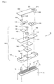
- FIG. 1 is an exploded perspective diagram illustrating a secondary battery according to one embodiment of the present invention.
- secondary battery 10 includes a bare cell, protection circuit board 300, and a mold resin part (not shown).
- the bare cell includes electrode assembly 12, can 11 for accommodating electrode assembly 12, and cap assembly 100 attached to an opening formed on the top of can 11.
- Electrode assembly 12 is made by forming each of cathode electrode 13 and anode electrode 15 into a plate shape in order to increase electric capacity, by laminating anode electrode 15 and cathode electrode 13 with separator 14 interposed therebetween, and by winding the laminated electrodes into a jelly roll type.
- Cathode tab 16 and anode tab 17 are attached to cathode electrode 13 and anode electrode 15, respectively, and extended upwardly.
- Insulation tape 18 is wound around a portion of each of cathode tab 16 and anode tab 17, where each of cathode tab 16 and anode tab 17 begins to stick out of electrode assembly 12. Insulation tape 18 prevents electrical short that can occur between cathode electrode 13 and anode electrode 15.
- Can 11 of secondary battery 10 is a container having a shape of rectangular parallelepipe, and has an open top and a side wall.
- Can 11 can be made of a metal material, and can be manufactured by deep drawing process. Therefore, can 11 also can be used as a terminal.
- Can 11 accommodates electrode assembly 12 and an electrolyte. Electrode assembly 12 is placed into can 11 through an opening formed on the top of can 11. After electrode assembly 12 is placed, the opening formed on the top of can 11 is sealed by cap assembly 100. The structure of can 11 will be described in detail later.
- Cap assembly 100 includes cap plate 110, electrode terminal 130 installed through terminal through-hole 111 that is formed on cap plate 110, terminal plate 150 that is disposed under cap plate and electrically connected to electrode terminal 130, and insulation plate 140 that is placed between cap plate 110 and terminal plate 150.
- Gasket 120 is installed on electrode terminal 130 to prevent electrical short between cap plate 110 and electrode terminal 130.
- Insulation case 190 can be positioned between terminal plate 150 and electrode assembly 12 in order to prevent short circuit between terminal plate 150 and electrode assembly 12.
- Anode electrode 15 of electrode assembly 12 is electrically connected to electrode terminal 130 through anode tab 17 and terminal plate 150.
- Cathode electrode 13 of electrode assembly 12 is electrically connected to cap plate 110 through cathode tab 16.
- insulation case 190 If insulation case 190 is provided, cathode tab 16 and anode tab 17 are supported by holes 191 formed on insulation case 190. The locations of anode tab 17 and cathode tab 16 can be switched to each other. In this case, the polarities of electrode terminal 130 and cap plate 110 also can be switched.
- Electrolyte inlet 112 is formed on one side of cap plate 110 in order to inject an electrolyte into can 11. Electrolyte inlet 112 is sealed by sealing part 160 after injecting an electrolyte into can 11.
- Protection circuit board 300 includes a panel made of resin and a protection circuit formed on the panel.
- the protection circuit protects the battery from getting overcharged or over-discharged during charging/discharging process, and is electrically connected with first connection terminal 360 and second connection terminal 370.
- First connection terminal 360 is electrically connected to cap plate 110 through first lead plate 210, and has positive polarity.
- Second connection terminal 370 is electrically connected to electrode terminal 130 through second lead plate 220 and positive temperature coefficient (PTC) element 170, and has a negative polarity.
- Insulation member 185 is provided for electrical insulation between PTC element 170 and cap plate 110.
- Second lead plate 220 and PTC element 170 can be replaced with a thermal breaker.
- First connection terminal 360 and second connection terminal 370 are electrically connected to input terminal 311 and output terminal 321, respectively, to be connected to an external electrical or electronic device.
- a mold resin part (not shown) is formed between cap plate 110 and protection circuit board 300 by filling hot melting resin into a space formed between cap plate 110 and protection circuit board 300, followed by solidification.
- the mold resin part protects components, which are installed in the space between cap plate 110 and protection circuit board 300, from being dislocated. It is necessary that the mold resin part should secure all component, which are installed between cap plate 110 and protection circuit board 300, from external force, such twist or bend, in order to protect the components.
- can 11 has an open top, through which electrode assembly 12 is inserted, and a side wall that encloses electrode assembly 12 accommodated in can 11.
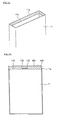
- side wall extension part 11 a is formed on an upper edge of the side wall of can 11.
- Side wall extension part 11 a protrudes upwards from the top edge of the side wall of can 11 beyond cap plate 110. Mold resin part 400 formed between cap plate 110 and protection circuit board 300, and adheres to side wall extension part 11 a.
- a dotted line indicates a region, below which cap plate 110 is located.
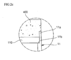
- Cap plate 110 has an upper plane and a lower plane, and the upper plane of cap plate 110 is positioned at around the dotted line (refer to FIG. 2c for a close-up view).
- side wall extension part 11 a is defined as a part that protrudes above the dotted line, where an edge of the upper plane of cap plate 110 contacts the side wall of can 11.
- the bottom end of side wall extension part 11 a is about the same vertical level with the upper plane of cap plate 110. Therefore, side wall extension part 11a protrudes upwards above the upper plane of cap plate 110, and an inner side surface of side wall extension part 11a contacts mold resin part 400.
- Side wall extension part 11 a can be a single piece surrounding mold resin part 400 as shown in FIG. 2a , or it is also possible to form a plurality of side wall extension parts 11a along the top edge of the side wall of can 11. In latter case, the side wall extension parts can be coupled to each other, and an inner side surface of each of side wall extension parts 11a contacts mold resin part 400. Therefore, side wall extension part 11 a increases the contact area with mold resin part 400, and effectively supports mold resin part 400, and therefore it is more effective to prevent mold resin part 400 from being twisted or bent.
- the structure of side wall extension part 11a is not limited to the structures described above, and there can be various structures and arrangements of the side wall extension parts to achieve the goal of the present invention.
- an angle between the inner side surface of side wall extension part 11a and the upper plane of cap plate 110 is approximately 90 degrees.
- mold resin part 400 adheres to both of the inner side surface of side wall extension part 11a and the upper plane of cap plate 110.
- the angle between the inner side surface of side wall extension part 11a a and the upper plane of cap plate 110 is approximately 90 degrees
- the side surface and the bottom of mold resin part 400, which adheres to the inner side surface of side wall extension part 11a and the upper plane of cap plate 110, respectively forms a right angle. If the angle between the inner side surface of side wall extension part 11a and the upper plane of cap plate 110 is acute (less than 90 degrees), it is difficult to install cap plate 110 inside can 11.
- the height of side wall extension part 11 a is smaller than the height of mold resin part 400.
- the height of side wall extension part 11a is defined as a distance between the top end and the bottom end of side wall extension part 11a.
- the bottom end of side wall extension part 11a is about the same vertical level with the upper plane of cap plate 110.
- Height of mold resin part 400 is a distance between the top surface of mold resin part 400, which contacts protection circuit board 300, and the bottom surface of mold resin part 400, which contacts cap plate 110. Mold resin part 400 adheres to the upper surface of side wall extension part 11a as well as the inner side surface of side wall extension part 11a.
- side wall extension part 11a is smaller than the height of mold resin part 400, there is a gap between the top end of side wall extension part 11a and the top surface of mold resin part 400, and accordingly, interaction between side wall extension part 11a and protection circuit board 300 can be avoided.
- seating groove 11b is formed on an inner side surface of the side wall of can 11, and is coupled to cap plate 110. As shown in FIG. 2c , cap plate 110 can be seated on seating groove 11b. Therefore, cap plate 110 covers the opening of the open top of can 11. Edges of the upper plane of cap plate 110, which contacts the side wall of can 11, are welded to the side wall of can 11 by laser welding method, and are sealed.
- connection terminals 360 and 370 installed in protection circuit board 300 can be electrically connected to side wall extension part 11a.
- first connection terminal 360 is described to be electrically connected to cap plate 110.
- one of first and second connection terminals 360 and 370 of protection circuit board 300 can be connected to side wall extension part 11a either directly or through a safety device, such as a PTC element, a thermal breaker, and others. Accordingly, a free space can be created on the upper plane of the cap plate 110 by removing components that are necessary to connect the connection terminal to the cap plate.
- a protrusion part (or a side wall extension part) is formed on a top edge of a side wall of a can, and the protrusion part adheres to a mold resin part. Therefore, the secondary battery has advantages that the battery can prevent the mold resin part from being twisted and bent, and therefore increases reliability of the battery.
Landscapes
- Chemical & Material Sciences (AREA)
- Chemical Kinetics & Catalysis (AREA)
- Electrochemistry (AREA)
- General Chemical & Material Sciences (AREA)
- Engineering & Computer Science (AREA)
- Manufacturing & Machinery (AREA)
- Microelectronics & Electronic Packaging (AREA)
- Battery Mounting, Suspending (AREA)
- Connection Of Batteries Or Terminals (AREA)
- Sealing Battery Cases Or Jackets (AREA)
Claims (5)
- Batterie, comprenant une boîte (11) comportant une extrémité ouverte et une paroi latérale, la boîte comprenant de plus une plaque de capuchon (110) comportant un plan recouvrant ladite extrémité ouverte, une carte de circuits de protection (300) disposée sur la plaque de capuchon (110), électriquement connectée à un ensemble d'électrodes (12) reçu dans la boîte (11), et une partie en résine moulée (400) entre la plaque de capuchon (110) et la carte de circuits de protection (300), dans laquelle la plaque de capuchon (110) est totalement reçue à l'intérieur de l'extrémité ouverte de la boîte et la paroi latérale s'étend au-delà du plan de la plaque de capuchon (110), caractérisée en ce que la paroi latérale de la boîte entoure partiellement la partie en résine moulée (400) qui s'étend au-delà de l'extrémité de la paroi latérale.
- Batterie selon la revendication 1, dans laquelle la plaque de capuchon (110) est reçue à l'intérieur de l'extrémité ouverte de telle sorte que la paroi latérale fasse saillie au-delà du plan de la plaque de capuchon (110) dans une direction sensiblement perpendiculaire au plan de la plaque de capuchon (110).
- Batterie selon l'une quelconque des revendications précédentes, dans laquelle une rainure de logement (116) est formée sur une surface intérieure de la paroi latérale, la plaque de capuchon (110) étant logée contre ladite rainure de logement (116).
- Batterie selon l'une quelconque des revendications 1 à 3, comprenant une borne de connexion connectée à la carte de circuits de protection (300), et électriquement connectée à une partie de la paroi latérale qui s'étend au-delà du plan de la plaque de capuchon (110).
- Batterie selon l'une quelconque des revendications précédentes, dans laquelle la plaque de capuchon (110) est électriquement connectée à l'ensemble d'électrodes (12).
Applications Claiming Priority (1)
| Application Number | Priority Date | Filing Date | Title |
|---|---|---|---|
| KR1020050134528A KR100778979B1 (ko) | 2005-12-29 | 2005-12-29 | 이차전지 |
Publications (3)
| Publication Number | Publication Date |
|---|---|
| EP1804314A2 EP1804314A2 (fr) | 2007-07-04 |
| EP1804314A3 EP1804314A3 (fr) | 2009-06-03 |
| EP1804314B1 true EP1804314B1 (fr) | 2012-03-07 |
Family
ID=37943861
Family Applications (1)
| Application Number | Title | Priority Date | Filing Date |
|---|---|---|---|
| EP06127284A Not-in-force EP1804314B1 (fr) | 2005-12-29 | 2006-12-28 | Batterie secondaire |
Country Status (3)
| Country | Link |
|---|---|
| US (1) | US7875384B2 (fr) |
| EP (1) | EP1804314B1 (fr) |
| KR (1) | KR100778979B1 (fr) |
Families Citing this family (18)
| Publication number | Priority date | Publication date | Assignee | Title |
|---|---|---|---|---|
| KR100601526B1 (ko) * | 2004-07-30 | 2006-07-19 | 삼성에스디아이 주식회사 | 리튬이온 이차전지 |
| JP4404818B2 (ja) * | 2004-07-30 | 2010-01-27 | 三星エスディアイ株式会社 | リチウムイオン二次電池 |
| US9172066B2 (en) * | 2007-09-10 | 2015-10-27 | Samsung Sdi Co., Ltd. | Protection circuit board, battery pack including the protection circuit board and method of fabricating the protection circuit board |
| KR100867928B1 (ko) * | 2007-09-27 | 2008-11-10 | 삼성에스디아이 주식회사 | 보호회로기판 및 이를 구비하는 배터리 팩 |
| KR100867923B1 (ko) | 2007-10-30 | 2008-11-10 | 삼성에스디아이 주식회사 | 보호회로기판을 구비하는 이차 전지 |
| JP5345633B2 (ja) | 2007-11-29 | 2013-11-20 | エルジー・ケム・リミテッド | 緻密な構造の二次バッテリーパック |
| KR100959872B1 (ko) * | 2008-01-04 | 2010-05-27 | 삼성에스디아이 주식회사 | 보호회로기판, 배터리 팩 및 이의 제조 방법 |
| KR100965711B1 (ko) * | 2008-05-09 | 2010-06-24 | 삼성에스디아이 주식회사 | 배터리 팩 |
| US8632910B2 (en) * | 2008-09-03 | 2014-01-21 | Samsung Sdi Co., Ltd. | Protection circuit board, secondary battery and battery pack |
| KR100965718B1 (ko) | 2008-10-08 | 2010-06-24 | 삼성에스디아이 주식회사 | 이차 전지 |
| KR101057578B1 (ko) * | 2009-07-10 | 2011-08-17 | 삼성에스디아이 주식회사 | 폴리머 전지팩 |
| KR101066001B1 (ko) * | 2009-09-01 | 2011-09-19 | 삼성에스디아이 주식회사 | 이차전지 |
| KR101073193B1 (ko) | 2009-09-28 | 2011-10-12 | 삼성에스디아이 주식회사 | 이차전지 |
| KR101084900B1 (ko) * | 2009-11-23 | 2011-11-17 | 삼성에스디아이 주식회사 | 이차 전지 및 그에 사용되는 회로기판 어셈블리 |
| EP2328210B1 (fr) * | 2009-11-25 | 2014-07-30 | Samsung SDI Co., Ltd. | Module de circuit de protection pour batterie secondaire |
| WO2018126439A1 (fr) * | 2017-01-06 | 2018-07-12 | 宁德时代新能源科技股份有限公司 | Structure de couvercle de batterie d'alimentation, batterie d'alimentation et module de batterie |
| KR101975745B1 (ko) | 2019-01-22 | 2019-05-07 | 김숙자 | 밀폐구조를 가지는 화장품용기 |
| KR101975747B1 (ko) | 2019-01-22 | 2019-08-28 | 김숙자 | 밀폐구조를 가지는 화장품용기 |
Family Cites Families (8)
| Publication number | Priority date | Publication date | Assignee | Title |
|---|---|---|---|---|
| CN1180507C (zh) * | 1999-03-30 | 2004-12-15 | 松下电器产业株式会社 | 具备电池保护电路的蓄电池 |
| JP3220681B2 (ja) | 1999-03-30 | 2001-10-22 | 松下電器産業株式会社 | 電池保護装置を備えた電池 |
| US6205034B1 (en) | 1999-09-24 | 2001-03-20 | Wilson Greatbatch Ltd. | Protection device for protecting an electrical component and method of assembling a battery with a protection device and an electrical component |
| JP2002110121A (ja) | 2000-09-26 | 2002-04-12 | Gs-Melcotec Co Ltd | 電池パック |
| JP2002164077A (ja) | 2000-11-22 | 2002-06-07 | Japan Storage Battery Co Ltd | 円筒形二次電池 |
| JP3766001B2 (ja) | 2001-07-06 | 2006-04-12 | 京セラ株式会社 | バッテリーとその製造方法 |
| US6803144B2 (en) | 2001-11-01 | 2004-10-12 | Nokia Corporation | Battery pack for electronic device |
| JP4589596B2 (ja) | 2002-03-22 | 2010-12-01 | パナソニック株式会社 | 電池パック |
-
2005
- 2005-12-29 KR KR1020050134528A patent/KR100778979B1/ko not_active Expired - Fee Related
-
2006
- 2006-12-21 US US11/642,854 patent/US7875384B2/en not_active Expired - Fee Related
- 2006-12-28 EP EP06127284A patent/EP1804314B1/fr not_active Not-in-force
Also Published As
| Publication number | Publication date |
|---|---|
| EP1804314A3 (fr) | 2009-06-03 |
| US20070154796A1 (en) | 2007-07-05 |
| KR100778979B1 (ko) | 2007-11-22 |
| US7875384B2 (en) | 2011-01-25 |
| EP1804314A2 (fr) | 2007-07-04 |
| KR20070071233A (ko) | 2007-07-04 |
Similar Documents
| Publication | Publication Date | Title |
|---|---|---|
| EP1804314B1 (fr) | Batterie secondaire | |
| KR100551887B1 (ko) | 이차전지 | |
| US7811686B2 (en) | Rechargeable battery | |
| EP1753053B1 (fr) | Batterie rechargeable | |
| US8268463B2 (en) | Secondary battery and method of fabricating the same | |
| KR100807029B1 (ko) | 이차전지 | |
| EP1906469A1 (fr) | Bloc-batterie | |
| KR101495294B1 (ko) | 전극 탭 보호 장치 및 이를 포함하는 이차 전지 | |
| KR100846955B1 (ko) | 원통형 이차전지 | |
| US7968228B2 (en) | Secondary battery | |
| KR101303396B1 (ko) | 몰딩부를 구비한 이차 전지 | |
| KR100696782B1 (ko) | 리튬이온 이차전지 | |
| KR100824885B1 (ko) | 이차전지 | |
| KR100788559B1 (ko) | 이차전지 | |
| KR101305461B1 (ko) | 이차 전지 | |
| KR100922741B1 (ko) | 이차전지 | |
| KR100659864B1 (ko) | 이차전지 | |
| KR100788558B1 (ko) | 팩 전지 | |
| KR100770098B1 (ko) | 이차 전지 | |
| KR20060037832A (ko) | 이차 전지 | |
| KR100563030B1 (ko) | 전지의 안전장치 | |
| KR100614387B1 (ko) | 밀봉홀더를 구비한 캔형 이차전지 | |
| KR100686858B1 (ko) | 이차 전지 | |
| KR20080016050A (ko) | 이차 전지 | |
| KR20060037834A (ko) | 이차 전지 |
Legal Events
| Date | Code | Title | Description |
|---|---|---|---|
| PUAI | Public reference made under article 153(3) epc to a published international application that has entered the european phase |
Free format text: ORIGINAL CODE: 0009012 |
|
| 17P | Request for examination filed |
Effective date: 20061228 |
|
| AK | Designated contracting states |
Kind code of ref document: A2 Designated state(s): AT BE BG CH CY CZ DE DK EE ES FI FR GB GR HU IE IS IT LI LT LU LV MC NL PL PT RO SE SI SK TR |
|
| AX | Request for extension of the european patent |
Extension state: AL BA HR MK YU |
|
| PUAL | Search report despatched |
Free format text: ORIGINAL CODE: 0009013 |
|
| AK | Designated contracting states |
Kind code of ref document: A3 Designated state(s): AT BE BG CH CY CZ DE DK EE ES FI FR GB GR HU IE IS IT LI LT LU LV MC NL PL PT RO SE SI SK TR |
|
| AX | Request for extension of the european patent |
Extension state: AL BA HR MK RS |
|
| RAP1 | Party data changed (applicant data changed or rights of an application transferred) |
Owner name: SAMSUNG SDI CO., LTD. |
|
| AKX | Designation fees paid |
Designated state(s): DE FR GB |
|
| 17Q | First examination report despatched |
Effective date: 20100511 |
|
| GRAP | Despatch of communication of intention to grant a patent |
Free format text: ORIGINAL CODE: EPIDOSNIGR1 |
|
| RIC1 | Information provided on ipc code assigned before grant |
Ipc: H01M 2/02 20060101AFI20110817BHEP Ipc: H01M 10/42 20060101ALI20110817BHEP Ipc: H01M 10/04 20060101ALI20110817BHEP Ipc: H01M 2/10 20060101ALI20110817BHEP |
|
| GRAS | Grant fee paid |
Free format text: ORIGINAL CODE: EPIDOSNIGR3 |
|
| GRAA | (expected) grant |
Free format text: ORIGINAL CODE: 0009210 |
|
| AK | Designated contracting states |
Kind code of ref document: B1 Designated state(s): DE FR GB |
|
| REG | Reference to a national code |
Ref country code: GB Ref legal event code: FG4D |
|
| REG | Reference to a national code |
Ref country code: DE Ref legal event code: R096 Ref document number: 602006028011 Country of ref document: DE Effective date: 20120510 |
|
| PLBE | No opposition filed within time limit |
Free format text: ORIGINAL CODE: 0009261 |
|
| STAA | Information on the status of an ep patent application or granted ep patent |
Free format text: STATUS: NO OPPOSITION FILED WITHIN TIME LIMIT |
|
| 26N | No opposition filed |
Effective date: 20121210 |
|
| REG | Reference to a national code |
Ref country code: DE Ref legal event code: R097 Ref document number: 602006028011 Country of ref document: DE Effective date: 20121210 |
|
| REG | Reference to a national code |
Ref country code: FR Ref legal event code: PLFP Year of fee payment: 10 |
|
| REG | Reference to a national code |
Ref country code: FR Ref legal event code: PLFP Year of fee payment: 11 |
|
| REG | Reference to a national code |
Ref country code: FR Ref legal event code: PLFP Year of fee payment: 12 |
|
| PGFP | Annual fee paid to national office [announced via postgrant information from national office to epo] |
Ref country code: DE Payment date: 20191217 Year of fee payment: 14 |
|
| PGFP | Annual fee paid to national office [announced via postgrant information from national office to epo] |
Ref country code: FR Payment date: 20191216 Year of fee payment: 14 |
|
| PGFP | Annual fee paid to national office [announced via postgrant information from national office to epo] |
Ref country code: GB Payment date: 20191224 Year of fee payment: 14 |
|
| REG | Reference to a national code |
Ref country code: DE Ref legal event code: R079 Ref document number: 602006028011 Country of ref document: DE Free format text: PREVIOUS MAIN CLASS: H01M0002020000 Ipc: H01M0050100000 |
|
| REG | Reference to a national code |
Ref country code: DE Ref legal event code: R119 Ref document number: 602006028011 Country of ref document: DE |
|
| GBPC | Gb: european patent ceased through non-payment of renewal fee |
Effective date: 20201228 |
|
| PG25 | Lapsed in a contracting state [announced via postgrant information from national office to epo] |
Ref country code: FR Free format text: LAPSE BECAUSE OF NON-PAYMENT OF DUE FEES Effective date: 20201231 |
|
| PG25 | Lapsed in a contracting state [announced via postgrant information from national office to epo] |
Ref country code: GB Free format text: LAPSE BECAUSE OF NON-PAYMENT OF DUE FEES Effective date: 20201228 Ref country code: DE Free format text: LAPSE BECAUSE OF NON-PAYMENT OF DUE FEES Effective date: 20210701 |