EP1804344A2 - Elektrischer Verbinder mit flexiblem Abschnitt - Google Patents
Elektrischer Verbinder mit flexiblem Abschnitt Download PDFInfo
- Publication number
- EP1804344A2 EP1804344A2 EP06256481A EP06256481A EP1804344A2 EP 1804344 A2 EP1804344 A2 EP 1804344A2 EP 06256481 A EP06256481 A EP 06256481A EP 06256481 A EP06256481 A EP 06256481A EP 1804344 A2 EP1804344 A2 EP 1804344A2
- Authority
- EP
- European Patent Office
- Prior art keywords
- electrical connector
- receiving
- shell
- housing
- pair
- Prior art date
- Legal status (The legal status is an assumption and is not a legal conclusion. Google has not performed a legal analysis and makes no representation as to the accuracy of the status listed.)
- Withdrawn
Links
Images


Classifications
-
- H—ELECTRICITY
- H01—ELECTRIC ELEMENTS
- H01R—ELECTRICALLY-CONDUCTIVE CONNECTIONS; STRUCTURAL ASSOCIATIONS OF A PLURALITY OF MUTUALLY-INSULATED ELECTRICAL CONNECTING ELEMENTS; COUPLING DEVICES; CURRENT COLLECTORS
- H01R13/00—Details of coupling devices of the kinds covered by groups H01R12/70 or H01R24/00 - H01R33/00
- H01R13/62—Means for facilitating engagement or disengagement of coupling parts or for holding them in engagement
- H01R13/627—Snap or like fastening
- H01R13/6275—Latching arms not integral with the housing
-
- H—ELECTRICITY
- H01—ELECTRIC ELEMENTS
- H01R—ELECTRICALLY-CONDUCTIVE CONNECTIONS; STRUCTURAL ASSOCIATIONS OF A PLURALITY OF MUTUALLY-INSULATED ELECTRICAL CONNECTING ELEMENTS; COUPLING DEVICES; CURRENT COLLECTORS
- H01R13/00—Details of coupling devices of the kinds covered by groups H01R12/70 or H01R24/00 - H01R33/00
- H01R13/648—Protective earth or shield arrangements on coupling devices, e.g. anti-static shielding
- H01R13/658—High frequency shielding arrangements, e.g. against EMI [Electro-Magnetic Interference] or EMP [Electro-Magnetic Pulse]
- H01R13/6581—Shield structure
- H01R13/6582—Shield structure with resilient means for engaging mating connector
Definitions
- the present invention relates to an electrical connector, and particularly to a micro electrical connector for mating with a complementary connector.
- the electronic member becomes more and more smaller. Therefore, the electrical connector applied in the electronic member becomes more and more smaller subject to the electronic member.
- the mini electrical connector always has a weak structure so that the electrical and mechanical connection between the mini connectors becomes not firm. Accordingly, the locking members are used between the mini connectors to confirm the electrical and mechanical connection.
- An object of the present invention is to provide an electrical connector to avoid damage to a complementary connector.
- an electrical connector adapted for connecting/disconnecting with/from a complementary connector in a front-to-back direction, comprises a shell, an insulative housing, a pair of locking members and a plurality of contacts received in the insulative housing.
- the shell comprises a plurality of surfaces, said surfaces defines a receiving space, one of the surfaces forms a pair of resilient tabs bent into the receiving space.
- the insulative housing received in the receiving space.
- the locking members assembled on the longitudinal opposite ends of the insulative housing and received in the receiving space, each forms a stopping projection projecting therefrom into the receiving space.
- the resilient tabs respectively, resist with the stopping projections of the locking members to stop the locking member has a movement.
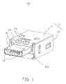
- FIG. 1 is an assembled, perspective view of an electrical connector in accordance with the present invention
- FIG. 2 is an exploded, perspective view of the electrical connector shown in FIG. 1;
- FIG. 3 is a view similar to FIG. 2, but taken from a different aspect
- FIG. 4 is a perspective view of a shell of the electrical connector
- FIG. 5 is a partially assembled, perspective view of the electrical connector
- FIG. 6 is another partially assembled, perspective view of the electrical connector.
- FIG. 7 is a view similar to FIG. 5, but taken from a different aspect.
- an electrical connector 100 in accordance with the present invention comprises a metal shell 1, an insulative housing 2, a plurality of contacts 4 received in the insulative housing 2, a pair of locking members 3, and a stopping block 5.
- the electrical connector 100 is in accordance with a micro USB standard.
- the electrical connector could be provided as other types.
- the metal shell 1 comprises a top shell 11 and a bottom shell 12.
- the top shell 11 comprises a main body 111, a connecting tab 115 and a mating portion 112.
- the main body 111 comprises a top surface 113, a pair of lateral surfaces 114 and a bottom surface 117 (shown in FIG. 4).
- the top surface 113 comprises a pair of first gaps 1130 and a second gap 1131 located more adjacent to the connecting tab 115 than that of first gaps 1130.
- Each lateral surface 114 defines a first cutout 1140 and a second cutout 1141.
- the bottom surface 117 has a jag (not labeled) thereon and a pair of resilient tabs 1170 bent inwardly from the opposite edges of the jag of the bottom surface 117.
- the connecting tab 115 is bent downwardly from the main body 111 along an up-to-down direction.
- the mating portion 112 extends forwardly from the connecting tab 115 along a front-to-back direction. Thereby, the mating portion 112 can move along the up-to-down direction relative to the main body 111 through the connecting tab 115.
- the connecting tab 115 also can extend from the lateral surface 114, accordingly, the mating portion 112 move along a lateral direction relative to the main body 111.
- a pair of rectangular cutouts 116 are defined at a portion where the connecting tab 115 and the main body 111 join.
- the rectangular cutouts 116 are applied for decreasing the intension of the connecting tab 115, therefore, the connecting tab 115 can be bent more easily.
- the mating portion 112 defines a mating part 118, a pair of positioning tabs 1181 extending backwardly from rear edge thereof, and a pair of receiving cutouts 1180 at a surface of the mating part 118.
- the bottom shell 12 comprises a bottom wall 121, a front wall 123, a rear wall 122 and a pair of lateral walls 124. These walls together define a receiving cavity (not labeled).
- the rear wall 122 of the bottom shell 12 has a receiving hole 1220 for cable (not shown) passing through.
- Each lateral wall 124 forms a block 1240 corresponding to the first cutout 1140 of the top shell 11 and a third cutout 1241 overlapped the second cutout 1141 of the top shell 11.
- the bottom wall 121 also defines a third gap 125 corresponding to the second gap 1131 of the top shell 11.
- Each contact 4 comprises a contacting portion 43, a tail portion 41 and a retaining portion 42 connecting the contacting portion 43 and the tail portion 42.
- Each tail portion 41 is bent from the retaining portion 42 downwardly/upwardly along the up-to-down direction. So, the space between adjacent tail portions 41 becomes bigger, and it facilitates to solder the cable on the tail portions 41.
- Each locking member 3 comprises a locking arm 31, a resilient arm 32 parallel with the locking arm 31 and a U-shape retaining arm 33.
- the locking arm 31 and the resilient arm 32 extend from the U-shape retaining arm 33 in a same direction.
- the locking arm 31 forms a bar 35 at the distal end thereof.
- the bar 35 forms an incline guiding face 36 thereon.
- the retaining arm 33 and the locking arm 31, respectively, forms a stopping projection 34, 37 for stopping the locking member 3 has a further movement into the housing 2.
- the insulative housing 2 comprises a base portion 21 and a tongue portion 22 extending forwardly from the base portion 21 along the front-to-back direction.
- the base portion 21 comprises a plurality of receiving passageways 211 therein, and a pair of receiving slits 213 at the opposite ends of the receiving passageways 211.
- a pair of positioning blocks 214 is, respectively, besides corresponding receiving slits 213.
- Each positioning block 214 comprises a receiving portion 216 for fixing the connecting tab 112 of the top shell 11.
- the base portion 21 defines an upper engaging hole 215 and a lower engaging hole (not shown), respectively, defining at a top face and a bottom face thereof.
- the upper engaging hole 215 communicates with the receiving passageways 211, the lower engaging hole is separated with the receiving passageways 211.
- the tongue portion 22 defines a plurality of receiving slots 221 communicating with corresponding receiving passageways 211.
- a pair of the projecting portions 222 are defined at the opposite ends at the tongue portion 22 and form a pair of holding slits 223 with the tongue portion 22.
- the holding slits 223 are used to receiving the distal ends of the locking members 3, and restrict the movement of the locking member 3 in the lateral direction.
- the base portion 21 further forms a pair of retaining projections 212 at the opposite lateral faces.
- the stopping block 5 receiving in the upper engaging hole 215 comprises a stopping section 51 and an engaging section 52.
- the contacts 4 are inserted into the housing 2 along the front-to-back direction.
- the retaining portion 42 of each contact 4 is received in corresponding receiving passageways 211, the contacting portion 43 extends into corresponding receiving slot 221 with tip end exposed outside, and the tail portion 41 is exposed beyond the housing 2.
- the stopping block 5 is inserted into the housing 2 through the upper engaging hole 215 along the up-to-down direction.
- the engaging section 52 of the stopping block 5 engages with the retaining portions 42 of the contacts 4, and the stopping section 51 engages with the inner face of the upper engaging hole 215.
- the upper face of the stopping block 5 is lower than the upper face of the base portion 21 of the housing 2.
- the locking members 3 are inserted into the receiving slits 213 with the distal end extending into the holding slits 223 and the stopping projections 34, 37 engaging with the rear face of the housing 2.
- the resilient arms 32 are exposed out of the housing 2.
- the resilient tabs 1170 are bent downwardly because of the pressure on the housing 2.
- the resilient tabs 1170 come back to original position, and respectively, resist with the stopping projections 37 of the locking member 3 to stop the locking member has a movement for stopping the locking member 3 to untie from the housing 2 in the front-to-back direction.
- the retaining projections 212 are received in corresponding second cutouts 1141.
- the tongue portion 22 is received in the mating part 118 of the mating portion 112 of the top shell 11.
- the positioning tabs 1181 are received in the receiving portions 216 of the positioning blocks 214.
- the positioning blocks 214 engage with the connecting tabs 115 in the up-to-down direction, and engage with rear edge of the mating portion 112 in the front-to-back direction.
- the positioning block 214 restricts the mating portion 112 and indicates weather the tongue portion 22 of housing 2 is completely received in the mating part 118.
- the stopping projection 34 of each locking member 3 is in a line with corresponding first gap 1130, and the bar 35 of each locking member 3 passes through corresponding receiving cutouts 1180 of the mating portion 112.
- the bottom shell 12 is assembled to the housing 2 and the top shell 11 from down to up.
- the blocks 1240 of the lateral wall 124 of the bottom shell 12 are received in the first cutouts 1140 of the top shell 11, the third cutouts 1241 hold the retaining projection 212 of the housing 2.
Landscapes
- Details Of Connecting Devices For Male And Female Coupling (AREA)
Applications Claiming Priority (2)
| Application Number | Priority Date | Filing Date | Title |
|---|---|---|---|
| CN 200520140443 CN2874834Y (zh) | 2005-12-27 | 2005-12-27 | 电连接器 |
| CNU2005201406146U CN2886853Y (zh) | 2005-12-29 | 2005-12-29 | 电连接器 |
Publications (2)
| Publication Number | Publication Date |
|---|---|
| EP1804344A2 true EP1804344A2 (de) | 2007-07-04 |
| EP1804344A3 EP1804344A3 (de) | 2008-11-05 |
Family
ID=37909678
Family Applications (2)
| Application Number | Title | Priority Date | Filing Date |
|---|---|---|---|
| EP06255385A Withdrawn EP1804343A3 (de) | 2005-12-27 | 2006-10-19 | Elektrischer Verbinder mit flexiblem Verbindungsteil |
| EP06256481A Withdrawn EP1804344A3 (de) | 2005-12-27 | 2006-12-20 | Elektrischer Verbinder mit flexiblem Abschnitt |
Family Applications Before (1)
| Application Number | Title | Priority Date | Filing Date |
|---|---|---|---|
| EP06255385A Withdrawn EP1804343A3 (de) | 2005-12-27 | 2006-10-19 | Elektrischer Verbinder mit flexiblem Verbindungsteil |
Country Status (1)
| Country | Link |
|---|---|
| EP (2) | EP1804343A3 (de) |
Families Citing this family (2)
| Publication number | Priority date | Publication date | Assignee | Title |
|---|---|---|---|---|
| CN204696372U (zh) * | 2014-05-26 | 2015-10-07 | 富士康(昆山)电脑接插件有限公司 | 插座连接器 |
| US9853398B2 (en) * | 2015-09-15 | 2017-12-26 | Htc Corporation | Plug connector and electronic assembly |
Family Cites Families (3)
| Publication number | Priority date | Publication date | Assignee | Title |
|---|---|---|---|---|
| US3768063A (en) * | 1972-08-16 | 1973-10-23 | R Coffman | Coaxial connector with an integral breakoff terminating resistor |
| TWM256006U (en) * | 2004-04-09 | 2005-01-21 | Advanced Connectek Inc | Hooking mechanism of a connector |
| TWM261868U (en) * | 2004-06-18 | 2005-04-11 | Advanced Connectek Inc | An electrical connector with a latch device |
-
2006
- 2006-10-19 EP EP06255385A patent/EP1804343A3/de not_active Withdrawn
- 2006-12-20 EP EP06256481A patent/EP1804344A3/de not_active Withdrawn
Also Published As
| Publication number | Publication date |
|---|---|
| EP1804343A2 (de) | 2007-07-04 |
| EP1804344A3 (de) | 2008-11-05 |
| EP1804343A3 (de) | 2009-08-12 |
Similar Documents
| Publication | Publication Date | Title |
|---|---|---|
| US7422465B2 (en) | Electrical connector having flexible mating portion | |
| US11146025B2 (en) | Compact electrical connector | |
| US7273397B2 (en) | Electrical connector having flexible mating portion | |
| US6585537B1 (en) | Cable end connector with locking member | |
| CN101133522B (zh) | 板安装电连接器 | |
| JP4308259B2 (ja) | 基板対基板電気コネクタ組立体 | |
| US7717755B2 (en) | Electrical connector with improved contacts | |
| US7232329B1 (en) | Cable connector assembly with unitary latch | |
| US6244910B1 (en) | Electrical box contact with stress limitation | |
| JP2005166300A (ja) | 大電流用雌端子及びシェル付き大電流用雌端子 | |
| CN101359788A (zh) | 连接器及连接器端子构造 | |
| US20100216327A1 (en) | Electrical connector featured usb/esata interfaces | |
| JP2008041664A (ja) | コネクタ | |
| EP2493024A2 (de) | Elektrischer Steckverbinder | |
| US7229298B2 (en) | Electrical connector having an improved grounding path | |
| JPH08255658A (ja) | 雄型コンタクト、雌型コンタクトおよび一対の嵌合コンタクト | |
| US6319063B1 (en) | Shielded electrical connector | |
| EP1548894B1 (de) | Verbinder | |
| JP3745318B2 (ja) | 電気コネクタ組立体 | |
| US6733310B2 (en) | Electrical connector with improved electrostatic discharge system | |
| JP4851510B2 (ja) | 電気コネクタ | |
| EP2028729A1 (de) | Steckverbinder für eine Buchse | |
| CN107230885A (zh) | 带锁定机构的连接器 | |
| US20070155227A1 (en) | Electrical connector | |
| US6186833B1 (en) | Hybrid connector with audio jack |
Legal Events
| Date | Code | Title | Description |
|---|---|---|---|
| PUAI | Public reference made under article 153(3) epc to a published international application that has entered the european phase |
Free format text: ORIGINAL CODE: 0009012 |
|
| AK | Designated contracting states |
Kind code of ref document: A2 Designated state(s): AT BE BG CH CY CZ DE DK EE ES FI FR GB GR HU IE IS IT LI LT LU LV MC NL PL PT RO SE SI SK TR |
|
| AX | Request for extension of the european patent |
Extension state: AL BA HR MK YU |
|
| PUAL | Search report despatched |
Free format text: ORIGINAL CODE: 0009013 |
|
| AK | Designated contracting states |
Kind code of ref document: A3 Designated state(s): AT BE BG CH CY CZ DE DK EE ES FI FR GB GR HU IE IS IT LI LT LU LV MC NL PL PT RO SE SI SK TR |
|
| AX | Request for extension of the european patent |
Extension state: AL BA HR MK RS |
|
| AKX | Designation fees paid | ||
| REG | Reference to a national code |
Ref country code: DE Ref legal event code: 8566 |
|
| STAA | Information on the status of an ep patent application or granted ep patent |
Free format text: STATUS: THE APPLICATION IS DEEMED TO BE WITHDRAWN |
|
| 18D | Application deemed to be withdrawn |
Effective date: 20090507 |