EP1804372A2 - Dispositif de conversion d'alimentation électrique et procédé de conversion d'énergie pour contrôler un générateur à induction à écran d'émission à double effet de champ - Google Patents
Dispositif de conversion d'alimentation électrique et procédé de conversion d'énergie pour contrôler un générateur à induction à écran d'émission à double effet de champ Download PDFInfo
- Publication number
- EP1804372A2 EP1804372A2 EP06127304A EP06127304A EP1804372A2 EP 1804372 A2 EP1804372 A2 EP 1804372A2 EP 06127304 A EP06127304 A EP 06127304A EP 06127304 A EP06127304 A EP 06127304A EP 1804372 A2 EP1804372 A2 EP 1804372A2
- Authority
- EP
- European Patent Office
- Prior art keywords
- voltage
- doubly
- converter
- power
- fed induction
- Prior art date
- Legal status (The legal status is an assumption and is not a legal conclusion. Google has not performed a legal analysis and makes no representation as to the accuracy of the status listed.)
- Granted
Links
Images


Classifications
-
- H—ELECTRICITY
- H02—GENERATION; CONVERSION OR DISTRIBUTION OF ELECTRIC POWER
- H02M—APPARATUS FOR CONVERSION BETWEEN AC AND AC, BETWEEN AC AND DC, OR BETWEEN DC AND DC, AND FOR USE WITH MAINS OR SIMILAR POWER SUPPLY SYSTEMS; CONVERSION OF DC OR AC INPUT POWER INTO SURGE OUTPUT POWER; CONTROL OR REGULATION THEREOF
- H02M3/00—Conversion of DC power input into DC power output
- H02M3/22—Conversion of DC power input into DC power output with intermediate conversion into AC
- H02M3/34—Conversion of DC power input into DC power output with intermediate conversion into AC by dynamic converters
- H02M3/38—Conversion of DC power input into DC power output with intermediate conversion into AC by dynamic converters using mechanical contact-making and -breaking parts to interrupt a single potential
-
- H—ELECTRICITY
- H02—GENERATION; CONVERSION OR DISTRIBUTION OF ELECTRIC POWER
- H02P—CONTROL OR REGULATION OF ELECTRIC MOTORS, ELECTRIC GENERATORS OR DYNAMO-ELECTRIC CONVERTERS; CONTROLLING TRANSFORMERS, REACTORS OR CHOKE COILS
- H02P9/00—Arrangements for controlling electric generators for the purpose of obtaining a desired output
- H02P9/46—Control of asynchronous generator by variation of capacitor
-
- H—ELECTRICITY
- H02—GENERATION; CONVERSION OR DISTRIBUTION OF ELECTRIC POWER
- H02J—ELECTRIC POWER NETWORKS; CIRCUIT ARRANGEMENTS OR SYSTEMS FOR SUPPLYING OR DISTRIBUTING ELECTRIC POWER; SYSTEMS FOR STORING ELECTRIC ENERGY
- H02J3/00—Circuit arrangements for AC mains or AC distribution networks
- H02J3/38—Arrangements for feeding a single network from two or more generators or sources in parallel; Arrangements for feeding already energised networks from additional generators or sources in parallel
- H02J3/381—Dispersed generators
-
- H—ELECTRICITY
- H02—GENERATION; CONVERSION OR DISTRIBUTION OF ELECTRIC POWER
- H02J—ELECTRIC POWER NETWORKS; CIRCUIT ARRANGEMENTS OR SYSTEMS FOR SUPPLYING OR DISTRIBUTING ELECTRIC POWER; SYSTEMS FOR STORING ELECTRIC ENERGY
- H02J3/00—Circuit arrangements for AC mains or AC distribution networks
- H02J3/38—Arrangements for feeding a single network from two or more generators or sources in parallel; Arrangements for feeding already energised networks from additional generators or sources in parallel
- H02J3/40—Synchronisation of generators for connection to a network or to another generator
- H02J3/44—Synchronisation of generators for connection to a network or to another generator with means for ensuring correct phase sequence
-
- H—ELECTRICITY
- H02—GENERATION; CONVERSION OR DISTRIBUTION OF ELECTRIC POWER
- H02P—CONTROL OR REGULATION OF ELECTRIC MOTORS, ELECTRIC GENERATORS OR DYNAMO-ELECTRIC CONVERTERS; CONTROLLING TRANSFORMERS, REACTORS OR CHOKE COILS
- H02P9/00—Arrangements for controlling electric generators for the purpose of obtaining a desired output
- H02P9/007—Control circuits for doubly fed generators
-
- H—ELECTRICITY
- H02—GENERATION; CONVERSION OR DISTRIBUTION OF ELECTRIC POWER
- H02J—ELECTRIC POWER NETWORKS; CIRCUIT ARRANGEMENTS OR SYSTEMS FOR SUPPLYING OR DISTRIBUTING ELECTRIC POWER; SYSTEMS FOR STORING ELECTRIC ENERGY
- H02J2101/00—Supply or distribution of decentralised, dispersed or local electric power generation
- H02J2101/20—Dispersed power generation using renewable energy sources
- H02J2101/28—Wind energy
-
- Y—GENERAL TAGGING OF NEW TECHNOLOGICAL DEVELOPMENTS; GENERAL TAGGING OF CROSS-SECTIONAL TECHNOLOGIES SPANNING OVER SEVERAL SECTIONS OF THE IPC; TECHNICAL SUBJECTS COVERED BY FORMER USPC CROSS-REFERENCE ART COLLECTIONS [XRACs] AND DIGESTS
- Y02—TECHNOLOGIES OR APPLICATIONS FOR MITIGATION OR ADAPTATION AGAINST CLIMATE CHANGE
- Y02E—REDUCTION OF GREENHOUSE GAS [GHG] EMISSIONS, RELATED TO ENERGY GENERATION, TRANSMISSION OR DISTRIBUTION
- Y02E10/00—Energy generation through renewable energy sources
- Y02E10/70—Wind energy
- Y02E10/76—Power conversion electric or electronic aspects
Definitions
- the present invention relates to an electric power converting device, and more particularly, to an electric power converting device and power converting method for controlling doubly-fed induction generators, which provides a synchronous generator for generating auxiliary electric power independently of a doubly-fed induction generator so as to generate electricity even in a system power-free environment, a grid-side converter is composed of a three-phase four-wire converter so as to generate a balanced voltage even in an unbalanced load condition and automatically synchronize a stator voltage of a doubly-fed induction generator and a system voltage with each other.
- a power converter refers to a device in which refines a low-quality primary energy having variable voltage and variable frequency characteristics caused by a variable wind speed or tidal current speed into a high-quality secondary energy having constant voltage and constant frequency characteristics so as to be linked to a power system in a new & renewable energy power generation system using wind power, tidal current power, etc.
- a generator most widely applied in a new & renewable energy power generation system market is a doubly-fed induction generator (DFIG) which features that a rotor winding is additionally provided to a cage-type generator so as to control slip power using the power converter.
- DFIG doubly-fed induction generator
- FIG. 1 is a block diagram illustrating the construction of a power converter for a doubly-fed induction generator including an AC-to-DC converter and a DC-to-AC converter according to the prior art
- FIG. 2 is a circuit diagram illustrating the construction of a power converter manufactured by Vestas Wind System according to the prior art
- FIG. 3 is a circuit diagram illustrating the construction of a power converter for a doubly-fed induction generator including two three-phase three-wire converters according to the prior art.
- the structure of the power converter used in the doubly-fed induction generator has a AC-DC-AC conversion function in which AC power is converted into DC power which in turn is converted into AC power.
- a grid-side converter for controlling the doubly-fed induction generator of the Vestas Wind System proposed in U.S. Pat. No. 6,856,040 B2 is configured of a three-phase bridge diode to have a unidirectional property.
- this configuration encounters a structural problem in that an active power and a power factor of a stator side of the doubly-fed induction generator cannot be controlled directly.
- the power factor is controlled by a passive capacitor, and energy transferred to the system employs a heat consumption method using a damping resistance, which makes it difficult to properly control the active power and the power factor of the stator side.
- 20% or so of the amount of electricity generation is recovered from the rotor winding and this recovered energy is consumed as heat, which leading to a degradation of efficiency.
- U.S. Pat. No. 5,798,631A has proposed a 3-leg IGBT or 3-leg IGCT structure which includes a three-phase three-wire converter to allow the grid-side converter to recover energy bidirectionally.
- Such a structure controls an active power and a power factor recovered from a stator side of the doubly-fed induction generator irrespective of the speed and load condition, and controls the power factor to be maintained at 1 so that 20% of energy recovered from a rotor side of the doubly-fed induction generator is recovered from the system and simultaneously the recovered energy is maximized.
- this structure controls a voltage applied across a capacitor connected between a generator-side converter and a grid-side converter to be always maintained at a constant magnitude so as to allow energy generated through the rotor winding to be transferred to the system.
- the above structure also has a problem in that in case where the system is unstable and instantaneous power interruption occurs except an ordinary state, the generated voltage is not in a three-phase balanced state. That is, when the capacity of the system is very large and the capacity of the distributed generation is small, no problem occurs. But, there is caused a problem in that since the above-mentioned control properties cannot be maintained in an unbalanced condition (load, power supply, etc.), the new & renewable energy power generation system (wind power/tidal current/tidal current power/wave power generation system) is stopped.
- the above structure entails a problem in that it can be used only in an environment where the system voltage exists since the power system voltage is directly applied to the stator winding to provide a magnetic flux component and hence the above structure is usable in a system-connected condition.
- the synchronization characteristic in which a stator voltage of the doubly-fed induction generator and a system voltage are synchronized with each other is sensitively affected by the installation position of an encoder.
- an aspect of exemplary embodiments of the present invention has been made to solve the aforementioned problems occurring in the prior art, and it is an object of the present invention to provide an electric power converting device for controlling a doubly-fed induction generator, which includes a synchronous generator for generating auxiliary electric power independently of the doubly-fed induction generator so as to separately generate electricity using the doubly-fed induction generator even in a system power-free environment.
- Another object of the present invention is to provide a grid-side converter of a doubly-fed induction generator, which is composed of a three-phase four-wire converter so as to generate a balanced voltage even in an unbalanced load (voltage) condition and have a function of constantly controlling a DC link voltage and controlling a power factor to be maintained at 1.
- Still another object of the present invention is to provide a method of controlling a generator-side converter of a doubly-fed induction generator, which automatically synchronize a stator voltage of the doubly-fed induction generator and a system voltage with each other at any time without being affected by the installation position of an encoder while maintaining a function of controlling active power and reactive power as it is.
- a further object of the present invention is to provide a power converting method for controlling a doubly-fed induction generator so as to drive the electric power converting device for controlling the doubly-fed induction generator.
- an electric power converting device for controlling doubly-fed induction generators comprising:
- a doubly-fed induction generator a power converter for converting electric energy of the doubly-fed induction generator for application to an alternate current (AC) system, a controller for PWM-controlling the power converter, and the AC system adapted to use an AC power supplied thereto from the power converter, wherein the doubly-fed induction generator further comprises:
- a synchronous generator for generating a separate auxiliary electric power independently of the doubly-fed induction generator
- an auxiliary converter for converting energy supplied thereto from the synchronous generator into a direct current (DC) power for application to the power converter
- the power converter includes:
- a generator-side converter for converting an AC power converted from electric energy of the doubly-fed induction generator into a DC power
- the DC link capacitor being disposed between the generator-side converter and the grid-side converter.
- the auxiliary converter comprises:
- a rectifier connected to the synchronous generator for converting an AC power supplied from the synchronous generator into a DC power
- a battery connected in parallel the smoothing capacitor and connected in parallel with the DC link capacitor of the power converter, for storing the output power of the smoothing capacitor.
- the auxiliary converter further comprises:
- bypass resistor connected between the smoothing capacitor and the battery for bypassing power overcharged in the smoothing capacitor
- a switch connected in series with the bypass resistor for selectively operating the bypass resistor.
- the grid-side converter of the power converter is configured of a three-phase four-wire structure having four legs each of which has two switching means.
- an electric power converting method of an electric power converting device for controlling doubly-fed induction generators including a first switch disposed between the synchronous generator and the auxiliary converter, a second switch the disposed between the auxiliary converter and the power converter, a third switch disposed between the power converter and the AC system, a fourth switch disposed between the doubly-fed induction generator and the AC system, a fifth switch disposed between the third switch and the fourth switch and the AC system, and a sixth switch disposed between the doubly-fed induction generator and the power converter, wherein the power converting method comprising the steps of:
- FIG. 1 is a block diagram illustrating the construction of a power converter for a doubly-fed induction generator including an AC-to-DC converter and a DC-to-AC converter according to the prior art;
- FIG. 2 is a circuit diagram illustrating the construction of a power converter manufactured by Vestas Wind System according to the prior art
- FIG. 3 is a circuit diagram illustrating the construction of a power converter for a doubly-fed induction generator including two three-phase three-wire converters according to the prior art
- FIG. 4a is a block diagram illustrating the construction of an electric power converting device for controlling a doubly-fed induction generator according to the present invention
- FIG. 4b is a circuit diagram illustrating the construction of an electric power converting device for controlling a doubly-fed induction generator according to one embodiment of the present invention
- FIG. 5 is a schematic view illustrating the construction of a to-be-controlled doubly-fed induction generator of an electric power converting device for controlling a doubly-fed induction generator according to the present invention
- FIG. 6 is a schematic view illustrating an assembly in which a doubly-fed induction generator and a synchronous generator are implemented integrally according to the present invention
- FIG. 7 is a circuit diagram illustrating the construction of an electric power converting device for controlling a doubly-fed induction generator, which includes a three-phase four-wire grid-side converter and has a strong control property even in an unbalanced load according to the present invention
- FIG. 8 is a block diagram illustrating SMPWM control process of a three-phase four-wire grid-side converter
- FIG. 9 is a block diagram illustrating a function of constantly controlling a DC link voltage and controlling a power factor to be maintained at 1 as well as the process of converting a coordinate system and controlling an SVPWM so as to control a three-phase four-wire grid-side converter;
- FIG. 10 is a block diagram illustrating the construction of a control unit of a doubly-fed induction generator having an automatic system connection function according to the present invention
- FIG. 11 is a block diagram illustrating a method of synchronizing a stator voltage of the doubly-fed induction generator and a system voltage with each other according to the present invention
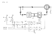
- FIG. 12 is a block diagram illustrating a method of synchronizing a stator voltage of the doubly-fed induction generator and a system voltage with each other and concurrently controlling active power and reactive power according to the present invention
- FIG. 13a is a flow chart illustrating an electric power converting method for controlling doubly-fed induction generators according to the present invention.
- FIG. 13a is a flow chart illustrating a method of controlling the operation of an electric power converting device for controlling doubly-fed induction generators according to the present invention.
- FIG. 4a is a block diagram illustrating the construction of an electric power converting device for controlling a doubly-fed induction generator according to the present invention
- FIG. 4b is a circuit diagram illustrating the construction of an electric power converting device for controlling a doubly-fed induction generator according to one embodiment of the present invention
- FIG. 5 is a schematic view illustrating the construction of a to-be-controlled doubly-fed induction generator of an electric power converting device for controlling a doubly-fed induction generator according to the present invention
- FIG. 6 is a schematic view illustrating an assembly in which a doubly-fed induction generator and a synchronous generator are implemented integrally according to the present invention.
- the electric power converting device for controlling the doubly-fed induction generators includes a doubly-fed induction generator 100, a synchronous generator 200, an auxiliary converter 300, a power converter 400, a controller 500 and an AC system 600.
- the doubly-fed induction generator 100 converts kinetic energy into electric energy
- the power converter 400 is connected to the doubly-fed induction generator so as to refines a low-quality electric energy into a high-quality electric energy for application to the AC system.
- the controller 500 PWM-controls the power converter 400, and the AC system 600 receives an AC power supplied from the power converter 400.
- the doubly-fed induction generator 100 is adapted to be connected to a power transmission means (not shown) such as a blade for converting a new and renewable energy source (wind power, tidal current power, tidal power, wave power, etc.) having a linear kinetic energy into a kinetic energy having a rotary force.
- a power transmission means such as a blade for converting a new and renewable energy source (wind power, tidal current power, tidal power, wave power, etc.) having a linear kinetic energy into a kinetic energy having a rotary force.
- the doubly-fed induction generator 100 converts the kinetic energy having a rotary force into an electric energy and is constructed to be connected at a shaft thereof to a main shaft of the blade via a speed increaser.
- the doubly-fed induction generator 100 consists of a stator 110 as a primary winding and a rotor 120 as a secondary winding for controlling a slip power.
- the stator 110 is a main passageway for transmission of energy of the doubly-fed induction generator 100
- the rotor 120 is an auxiliary passageway through which the slip power is transmitted.
- FIG. 6 there is shown an implementation of the structure in which the doubly-fed induction generator 100 and the synchronous generator 200 are connected integrally.
- the integral structure of the doubly-fed induction generator 100 and the synchronous generator 200 allows the synchronous generator 200 to rotate using a part of a rotary force transmitted to the main shaft of the blade to secure an auxiliary power.
- the doubly-fed induction generator 100 and the synchronous generator 200 as shown in FIG. 6, are constructed integrally with each other by sharing a coaxial shaft, but may be constructed in a separated type using a means such as a gear.
- the synchronous generator 200 is a generator for securing an auxiliary power required by the power converter 400, which independently secures a separate DC power required by the doubly-fed induction generator 100 and the power converter 400 so as to enable conversion of power even in a system power-free condition.
- the synchronous generator 200 is classified into a type which has a built-in a permanent magnet and a type which a built-in winding.
- the synchronous generator is preferably constructed of the permanent magnet-embedded type since it does not require a separate additional device and can generate an output voltage proportional to the number of revolutions of a rotor of the generator.
- the auxiliary converter 300 includes a rectifier 310, a smoothing capacitor 320 and a battery 33.
- a bypass resistor 341 and a switch 342 are further provided between the smoothing capacitor 320 and the battery 330.
- the auxiliary converter 300 is connected with the synchronous generator 100 so as to convert energy supplied thereto from the synchronous generator 200 into a DC power for application to the power converter 400.
- the rectifier 310 is connected to the synchronous generator 200 so as to convert an AC power supplied from the synchronous generator into a DC power, and the smoothing capacitor 320 is connected in parallel with the rectifier 310 to smooth the output power of the rectifier 310.
- the battery 330 is connected in parallel the smoothing capacitor 320 and is connected in parallel with the DC link capacitor 420 of the power converter so as to store the output power of the smoothing capacitor 320.
- bypass resistor 341 is connected between the smoothing capacitor 320 and the battery 330 so as to bypass power overcharged in the smoothing capacitor 320, and the switch 342 is connected in series with the bypass resistor 341 so as to selectively operate the bypass resistor.
- the present invention features that DC power stored in the battery 330 is applied across the DC link capacitor 420 of the power converter 400 so as to allow the electric power converting device for controlling the doubly-fed induction generator to independently secure energy for activation regardless of the system power.
- the power converter 400 includes a generator-side converter 410, a DC link capacitor 420 and a grid-side converter 430.
- the generator-side converter 410 converts an AC power converted from electric energy of the doubly-fed induction generator 100 into a DC power
- the DC link capacitor 420 is disposed between the generator-side converter 410 and the grid-side converter 430 in such a fashion as to be connected in parallel with the auxiliary converter 300 so as to store electric energy.
- the DC link capacitor 420 generates an independent power source irrespective of the system voltage, i.e., without external power source using the synchronous generator 200 so as to charge voltage at a DC link terminal (a terminal between a P node and an N node inside the power converter.
- the grid-side converter 430 re-converts the DC power converted by the generator-side converter 410 into the AC power for application to the AC system 600.
- the present invention proposes a grid-side converter 430 having a three-phase four-wire converter or four-leg converter structure in which a fourth neutral leg is additionally included in a conventional three-phase three-wire converter or three leg converter so as to generate a balanced voltage even in such an unbalanced condition.
- the grid-side converter 430 controls a zero sequence voltage component or a zero sequence current component generated in an unbalanced condition. That is, the grid-side converter 430 is constructed to apply the zero sequence voltage to control neutral current of the AC system 600.
- the grid-side converter 430 is configured of a three-phase four-wire structure having four legs each of which has two switching means 431, and the center of an additionally provided fourth leg is connected with a neutral point of the AC system.
- the switching means 431 is preferably constructed of an insulated gate bipolar transistor (IGBT).
- the grid-side converter 430 is configured of the three-phase four-wire converter structure so that the electric power converting device for controlling the doubly-fed induction generator according to the present invention has a strong control property with respect to the above-mentioned unbalanced condition, and the generator-side converter 410 employs the same three-phase three-wire structure as an existing structure.
- the electric power converting device for controlling the doubly-fed induction generator is constructed such that the generator-side converter 410 has three-phase three-wire converter structure and the grid-side converter 430 has the three-phase four-wire converter so that 1) an active power and a power factor of a stator of the doubly-fed induction generator is controlled using the generator-side converter 410 of the doubly-fed induction generator 100, and 2) a DC link voltage and a system power factor are normally controlled using the grid-side converter 430 even when the system voltage is in an unbalanced condition.
- the controller 500 serves to PWM-controls the power converter 400, and preferably SVPWM (Space Vector Power Width Modulation)-controls the power converter 400 in the electric power converting device for controlling the doubly-fed induction generator according to the present invention.
- SVPWM Space Vector Power Width Modulation
- the AC system 600 is adapted to use an AC power supplied thereto from the power converter 400.
- the electric power converting device for controlling the doubly-fed induction generator according to the present invention includes an AC system having an unbalanced condition due to a non-linear load or an unbalanced load.
- the electric power converting device for controlling the doubly-fed induction generator includes an auxiliary converter 300 having a rectifier 310, a smoothing capacitor 320 and a battery 330, a power converter having a generator-side converter 410, a DC link capacitor 420 and a grid-side converter 430, and first to sixth switches (SW1 ⁇ SW6) for driving the electric power converting device for controlling the doubly-fed induction generator.
- the second switch electrically connects the auxiliary converter 300 and the power converter 400 through the P terminal and the N terminal.
- FIG. 7 is a circuit diagram illustrating the construction of an electric power converting device for controlling a doubly-fed induction generator, which includes a three-phase four-wire grid-side converter and has a strong control property even in an unbalanced load according to the present invention
- FIG. 8 is a block diagram illustrating SMPWM control process of a three-phase four-wire grid-side converter
- FIG. 9 is a block diagram illustrating the process of conversion of a coordinate system and control of an SVPWM of the three-phase four-wire grid-side converter.
- V bn V bf + V fn
- V cn V cf + V fn
- V fn ⁇ - V max 2 , if V min > 0 - V min 2 , if V max ⁇ 0 - V max + V min 2 , Otherwise
- the pole voltage should be limited to the following range: Equation 5 - V dc 2 ⁇ V an ⁇ V dc 2 - V dc 2 ⁇ V bn ⁇ V dc 2 - V dc 2 ⁇ V cn ⁇ V dc 2 - V dc 2 ⁇ V fn ⁇ V dc 2
- the three-phase four-wire grid-side converter 430 of the electric power converting device for controlling a doubly-fed induction generator controls an balanced output voltage, constantly controls a DC link voltage, and controls the power factor to be maintained at 1 based on conversion of a coordinate system and control of an SVPWM.
- a "3 ⁇ ->2 ⁇ ” block denotes a step in which a three-phase (a, b, c) rest coordinate system is converted into a two-phase (d, q) rest coordinate system
- a "2 ⁇ ->3 ⁇ ” block denotes a step in which the two-phase (d, q) rest coordinate system is converted into the three-phase (a, b, c) rest coordinate system.
- a "2( ⁇ ->2 ⁇ ” block denotes a step in which a two-phase (d, q) rest coordinate system is converted into a two-phase (d, q) synchronous coordinate system
- a "2 ⁇ ->2 ⁇ ” block denotes a step in which the two-phase (d, q) synchronous coordinate system is converted into the two-phase (d, q) rest coordinate system.
- the coordinate conversion equation used is a known equation, its detailed description will be omitted.
- a d-axis current reference value (i d e* ) is set to 0 so as to control a grid-side power factor to be maintained at 1
- a zero sequence component reference value (i 0 e* ) is set to 0 so as to control a load voltage to be always maintained in a three-phase balanced state.
- a-axis current reference value (i q e* ) is set as an output value to constantly control the voltage stored in the DC link capacitor 420 disposed between the generator-side converter 410 and the grid-side converter 430.
- FIG. 10 is a block diagram illustrating the construction of a control unit of a doubly-fed induction generator having an automatic system connection function according to the present invention
- FIG. 11 is a block diagram illustrating a method of synchronizing a stator voltage of the doubly-fed induction generator and a system voltage with each other according to the present invention.
- FIG. 12 is a block diagram illustrating a method of synchronizing a stator voltage of the doubly-fed induction generator and a system voltage with each other and concurrently controlling active power and reactive power according to the present invention. This is intended to control three-phase three-wire generator-side converter.
- control unit of the doubly-fed induction generator having an automatic system connection function includes the controller 500 of the doubly-fed induction generator of FIG. 4a, a slip angle calculator 550, and a synchronization means 560.
- the controller 500 controls a q-axis current compensating component (i qre_comp ) to be combined at a position where a q-axis reference value component of a rotor current determined as a controlled active power (controlled speed, controlled torque) output and a q-axis component of an actual rotor current meet with each other, and controls a d-axis current compensating component (i dre_comp ) to be combined at a position where a d-axis reference value component of a rotor current determined as a controlled reactive power (or controlled power factor) output and a d-axis component of an actual rotor current meet with each other to control the current of the d-axis and q-axis so as to control an active power and a reactive power in a stator winding.
- a q-axis current compensating component i qre_comp
- the slip angle calculator 550 receives a rotational angle ( ⁇ r ) of the doubly-fed induction generator from the generator-side converter 410, an offset angle ( ⁇ offset ) generated from the synchronization means 560, and a stator angle ( ⁇ s ) calculated from a stator voltage so as to output a slip angle ( ⁇ sl ) for application to the controller 500.
- the slip angle calculator 550 determines the slip angle ( ⁇ sl ) using the stator voltage angle ( ⁇ s ) calculated from voltage induced from the stator winding, the rotational angle ( ⁇ r ) of the generator and offset angle ( ⁇ offset ) output from the synchronization means 560. At this time, the slip angle ( ⁇ sl ) is used in a coordinate conversion process to control a slip power (or slip speed).
- the slip angle calculator 550 further includes a low pass filter (LPF) 551 having a cut-off frequency of approximately 5kHz when a grid-side phase voltage ⁇ as ⁇ bs , ⁇ cs and a voltage ⁇ at' ⁇ bt , ⁇ ct induced to the stator winding are converted into a d-q coordinate system to calculate v ds ⁇ 1 e , v qs ⁇ 1 e , v ds ⁇ 2 e , v qs ⁇ 2 e .
- LPF low pass filter
- the synchronization means 560 calculates the offset angle ( ⁇ offset ) to output the calculated result to the slip angle calculator 550 so as to control phase synchronization, and outputs a d-axis current compensating component ( i dre_comp ) of the rotor current and a q-axis current compensating component ( i qre_comp ) of the rotor current to the controller 500.
- the synchronization means 560 allows a voltage error ( ⁇ d_err ) between a d-axis component v ds ⁇ 2 e of the voltage induced from the stator winding and a d-axis component v ds ⁇ 1 e of the system voltage to be controlled to be maintained at 0 using a PI controller 561 so as to make the voltage induced from the stator winding and the system voltage identical to each other in terms of phase, and determines an output of the PI controller 561 as the offset angle ( ⁇ offset ) for correcting an encoder phase angle.
- the synchronization means 560 allows a voltage error ( ⁇ d_err ) between a q-axis component v qs ⁇ 2 e of the voltage induced from the stator winding and a q-axis component v qs ⁇ 1 e of the system voltage to be controlled to be maintained at 0 using the PI controller 561 so as to make the voltage induced from the stator winding and the system voltage identical to each other in terms of magnitude, and determines an output of the PI controller 561 as a q-axis current compensating component ( i dre_comp ) .
- the q-axis current compensating component ( i dre_comp ) is always set to 0.
- the synchronization means 560 further comprises a limiter 562 for preventing the d-axis current compensating component ( i dre_comp ) of the rotor current from being increased sharply by an output of the PI controller 561, and has a feedback component so as to increase a convergence speed.
- the rotor current of the doubly-fed induction generator when the rotor current of the doubly-fed induction generator is represented as the d-q coordinate system, it can be divided into the d-axis component and the q-axis component.
- a difference between a d-axis component of the voltage induced to a stator side and a d-axis component of a grid-side voltage becomes an input signal of the PI controller 561
- a result of the PI controller 561 is designed to be the offset angle ( ⁇ offset ) for synchronization
- the q-axis component of the voltage induced to a stator side is designed to be identical to the q axis component of a grid-side voltage using the PI controller
- the output of the PI controller is designed to be a current compensating component added to the d-axis component of the rotor current.
- the d-axis current component of the rotor is identical in magnitude to the current compensating component added for synchronization, which means that the d-axis current component is operated as a parameter for adjusting the magnitude of the stator voltage induced to the stator side.
- the inventive doubly-fed induction generator having an automatic system connection function of FIG. 10
- FIG. 13a is a flow chart illustrating an electric power converting method for controlling doubly-fed induction generators according to the present invention
- FIG. 13a is a flow chart illustrating an operation controlling method of an electric power converting device for controlling doubly-fed induction generators according to the present invention.
- the electric power converting device for controlling doubly-fed induction generators includes a first switch disposed between the synchronous generator and the auxiliary converter, a second switch the disposed between the auxiliary converter and the power converter, a third switch disposed between the power converter and the AC system, a fourth switch disposed between the doubly-fed induction generator and the AC system, a fifth switch disposed between the third switch and the fourth switch and the AC system, and a sixth switch disposed between the doubly-fed induction generator and the power converter (see FIG. 4b).
- step (a) the first to sixth switches are turned off to be initialized.
- the controller 500 determines whether or not the electric power converting device for controlling a doubly-fed induction generator 100 is in a normal state.
- an independent system voltage is measured to check voltage dip, voltage swell, flicker, etc., to determine if the electric power converting device for controlling a doubly-fed induction generator 100 is in a normal state.
- the controller 500 determines if the drive of the electric power converting device for controlling a doubly-fed induction generator 100 is enabled by considering whether or not the power converter 400 is in a normal state, and an over-wind speed or over-speed of tidal current condition exists.
- step (b) if it is determined that the electric power converting device for controlling the doubly-fed induction generator 100 is in a normal state, the program proceeds to step (d) in which the speed of a new and renewable energy source is measured.
- the speed of a new and renewable energy source means wind speed or speed of tidal current, etc.
- the speed of a new and renewable energy source is compared with a reference speed.
- the speed of a new and renewable energy source is compared with a reference value such as a cut-in speed, i.e., a minimum wind speed (or minimum current speed value) so as to judge whether the electric power converting device for controlling the doubly-fed induction generator 100 reaches a drivable condition after measuring the wind speed or current speed.
- step (b) if it is determined that the electric power converting device for controlling the doubly-fed induction generator 100 is not in a normal state, the program proceeds to step (e) where the sixth switch is turned on so as to stop the electric power converting device.
- step (d) If it is determined at step (d) that the measured speed of the new and renewable energy source is larger than a reference speed, the program proceeds step (f) where the controller 500 determines whether or not a terminal voltage of the battery 330 of the auxiliary converter 300 exceeds a reference voltage.
- step (h) the controller 500 checks the charge state of the battery 330 of the auxiliary converter 300.
- step (d) If it is determined at step (d) that the measured speed of the new and renewable energy source is smaller than the reference speed, the program returns to the previous step (c) via step (g), where the controller 500 repeatedly performs the step (c).
- step (f) If it is determined at step (f) that the terminal voltage of the battery 330 of the auxiliary converter 300 exceeds the reference voltage, i.e., the charging of the battery is completed, the program proceeds to step (h) where the controller 500 turns the second switch on so as to interconnect the auxiliary converter 300 and the DC link capacitor 420.
- the second switch is turned on so as to charge the DC link capacitor 420 using the energy (current and voltage) charged in the battery 330 of the auxiliary converter 300.
- step (f) If, on the other hand, it is determined at step (f) that the terminal voltage of the battery 330 of the auxiliary converter 300 does not exceed the reference voltage, i.e., the charging of the battery is not completed, the program proceeds to step (i) where the controller 500 turns the first switch on to charge the battery beyond the reference voltage, and then returns to the previous step (f) where the controller repeatedly perform the step (f). In this case, the first switch is turned on using the synchronous generator 200 so as to charge the battery through the auxiliary converter 300.
- the DC link capacitor 420 is charged at step (f) so that a DC voltage charged in the DC link capacitor 420 is converted into an AC voltage by the grid-side converter 430 to generate an AC power for application to the AC system 600 by turning on the third switch.
- the converted AC voltage is an independent power source having a system frequency and a system voltage.
- step (k) the controller determines whether or not the voltage generated from the doubly-fed induction generator 100 and the voltage generated from the grid-side converter 430 are synchronized with each other. If it is determined at step (k) that the voltage generated from the doubly-fed induction generator 100 and the voltage generated from the grid-side converter 430 are synchronized with each other, the program proceeds to step (1) where the fourth switch is turned on.
- step (k) if it is determined at step (k) that the voltage generated from the doubly-fed induction generator 100 and the voltage generated from the grid-side converter 430 are not synchronized with each other, the program proceeds to step (m) where the generator-side converter 410 is turned on so as to regulate the magnitude of a d-axis current component within the generator-side converter 410 for synchronization.
- step (n) the controller turns on the fifth switch so as to transmit the AC voltage generated from the grid-side converter 430 to the AC system 600, and then the program returns to the previous step (b) via step (o), where the controller 500 repeatedly performs the step (b) to determine whether or not the electric power converting device for controlling a doubly-fed induction generator 100 is in a normal state.
- the synchronous generator as an auxiliary generator is included independently of the doubly-fed induction generator as a main generator so that an auxiliary power is secured irrespective of the system power to thereby eliminate the need of the system power.
- the doubly-fed induction generator can be applied to a new and renewable energy system using a marine wind power, tidal current power, wave power, etc., located remotely from the system line to thereby construct an independent system.
- the grid-side converter is constructed of a three-phase four-wire converter so that a stable balanced voltage is supplied to generate electricity without stopping the operation of the new and renewable energy source (wind power, tidal current power, tidal power, wave power, etc.) even in an unbalanced condition.
- a control method of the generator-side converter which can automatically synchronize a stator voltage of the doubly-fed induction generator and a system voltage with each other at any time without being affected by the installation position of an encoder while maintaining a function of controlling active power and reactive power as it is, thereby improving the control property of the electric power converting device.
Landscapes
- Engineering & Computer Science (AREA)
- Power Engineering (AREA)
- Control Of Eletrric Generators (AREA)
Applications Claiming Priority (1)
| Application Number | Priority Date | Filing Date | Title |
|---|---|---|---|
| KR1020050135062A KR100668118B1 (ko) | 2005-12-30 | 2005-12-30 | 권선형 유도 발전기 제어용 전력변환장치 및 전력변환방법 |
Publications (3)
| Publication Number | Publication Date |
|---|---|
| EP1804372A2 true EP1804372A2 (fr) | 2007-07-04 |
| EP1804372A3 EP1804372A3 (fr) | 2013-02-27 |
| EP1804372B1 EP1804372B1 (fr) | 2014-05-28 |
Family
ID=37966448
Family Applications (1)
| Application Number | Title | Priority Date | Filing Date |
|---|---|---|---|
| EP06127304.1A Active EP1804372B1 (fr) | 2005-12-30 | 2006-12-28 | Dispositif de conversion d'alimentation électrique et procédé de conversion d'énergie pour contrôler un générateur à induction à écran d'émission à double effet de champ |
Country Status (3)
| Country | Link |
|---|---|
| US (1) | US7579702B2 (fr) |
| EP (1) | EP1804372B1 (fr) |
| KR (1) | KR100668118B1 (fr) |
Cited By (10)
| Publication number | Priority date | Publication date | Assignee | Title |
|---|---|---|---|---|
| WO2009150464A1 (fr) | 2008-06-13 | 2009-12-17 | Wind Technologies Limited | Générateur d'énergie |
| CN101888190A (zh) * | 2010-05-14 | 2010-11-17 | 北京景新电气技术开发有限责任公司 | 一种基于预测控制的pwm整流器的控制方法 |
| CN101771356B (zh) * | 2010-02-02 | 2012-03-07 | 山特电子(深圳)有限公司 | 一种ups的电压补偿值获取方法及其应用 |
| CN102377194A (zh) * | 2010-08-12 | 2012-03-14 | 北京动力机械研究所 | 风力发电并网的切换系统及方法 |
| CN102427236A (zh) * | 2011-12-19 | 2012-04-25 | 重庆大学 | 不平衡电压下采用串联网侧变换器的双馈感应风电系统抑制总输出无功功率波动的方法 |
| EP2866323A1 (fr) * | 2013-09-11 | 2015-04-29 | General Electric Company | Système d'alimentation électrique auxiliaire et procédé permettant de réguler les tensions de celui-ci |
| EP2161443A3 (fr) * | 2008-09-08 | 2015-06-24 | General Electric Company | Éolienne dotée d'un convertisseur d'alimentation principale et d'un convertisseur d'alimentation auxiliaire et procédé de contrôle associé |
| EP3016272A1 (fr) * | 2014-10-30 | 2016-05-04 | Siemens Aktiengesellschaft | Commande du flux d'énergie à partir d'une machine électrique à impédance non équilibrée |
| EP2653720A3 (fr) * | 2012-04-16 | 2016-09-28 | Envision Energy (Denmark) ApS | Éolienne avec un générateur primaire et secondaire et procédé de fonctionnement de ladite éolienne |
| EP3402065A1 (fr) * | 2017-05-10 | 2018-11-14 | General Electric Company | Système de production d'énergie et son procédé de fonctionnement |
Families Citing this family (56)
| Publication number | Priority date | Publication date | Assignee | Title |
|---|---|---|---|---|
| EP1625457A4 (fr) * | 2003-05-02 | 2015-04-22 | Xantrex Technology Inc | Systeme de commande de generateur d'induction a double alimentation |
| DE102004013131A1 (de) * | 2004-03-17 | 2005-10-06 | Siemens Ag | Windkraftanlage |
| WO2008064472A1 (fr) * | 2006-11-28 | 2008-06-05 | The Royal Institution For The Advancement Of Learning/Mcgill University | Procédé et système permettant de commander une machine à induction à double alimentation |
| US8513911B2 (en) | 2007-05-11 | 2013-08-20 | Converteam Technology Ltd. | Power converters |
| GB2449119B (en) * | 2007-05-11 | 2012-02-29 | Converteam Technology Ltd | Power converters |
| KR100886194B1 (ko) * | 2007-06-08 | 2009-02-27 | 한국전기연구원 | 계통 연계형 고압 권선형 유도 발전기 제어 장치 |
| DE102008011224A1 (de) * | 2008-02-26 | 2009-08-27 | Robert Bosch Gmbh | Generatorvorrichtung mit Überspannungsüberwachung |
| ES2360433B1 (es) * | 2008-05-23 | 2012-04-20 | Ingeteam S.A. | Método y sistema de control de una instalación eólica ante faltas de red. |
| KR101010352B1 (ko) * | 2008-05-30 | 2011-01-25 | 삼성중공업 주식회사 | 전력 제어 장치 및 방법 |
| KR100986269B1 (ko) * | 2008-05-30 | 2010-10-07 | 삼성중공업 주식회사 | 농형유도 발전시스템의 전력변환 장치 |
| KR100986268B1 (ko) * | 2008-06-04 | 2010-10-07 | 삼성중공업 주식회사 | 영구자석 동기발전 시스템의 전력변환 장치 |
| ES2333393B1 (es) * | 2008-06-06 | 2011-01-07 | Accioona Windpower, S.A | Sistema y metodo de control de un aerogenerador. |
| DE102008028809B3 (de) * | 2008-06-19 | 2010-04-01 | Repower Systems Ag | Ansteuerschaltung und -verfahren für Wechselrichter von Windenergieanlagen |
| US8319358B2 (en) | 2008-06-30 | 2012-11-27 | Demand Energy Networks, Inc. | Electric vehicle charging methods, battery charging methods, electric vehicle charging systems, energy device control apparatuses, and electric vehicles |
| US8097967B2 (en) | 2008-06-30 | 2012-01-17 | Demand Energy Networks, Inc. | Energy systems, energy devices, energy utilization methods, and energy transfer methods |
| EP2161821B1 (fr) * | 2008-09-03 | 2020-06-17 | General Electric Company | Générateur à commande magnétique |
| DE102008037449B4 (de) * | 2008-10-14 | 2010-10-14 | Kenersys Gmbh | Windenergieanlage |
| US9494138B2 (en) * | 2009-08-14 | 2016-11-15 | Vestas Wind Systems A/S | Variable speed wind turbine, and a method for operating the variable speed wind turbine during a power imbalance event |
| US8093746B2 (en) | 2009-12-16 | 2012-01-10 | General Electric Company | Control of four-leg transformerless uninterruptible power supply |
| JP5073054B2 (ja) * | 2010-02-18 | 2012-11-14 | 三菱重工業株式会社 | 風力発電装置の保守運転方法及び風力発電装置 |
| US8420986B2 (en) * | 2010-03-09 | 2013-04-16 | Bsh Home Appliances Corporation | Frequency-modulated electric element control |
| AU2010352434B2 (en) * | 2010-04-29 | 2014-12-11 | Ingeteam Power Technology, S.A. | System and method for control an electric generator |
| KR100975072B1 (ko) * | 2010-05-12 | 2010-08-11 | 주식회사 대흥기전 | 브러시리스 자여자 동기발전기 |
| US20140070534A1 (en) * | 2010-05-28 | 2014-03-13 | Mitsubishi Heavy Industries, Ltd. | Power generating apparatus of renewable energy type and operation method thereof |
| US8957543B2 (en) * | 2010-10-15 | 2015-02-17 | Nextek Power Systems, Inc. | Arrangement for and method of dynamically managing electrical power between an electrical power source and an electrical load |
| US9312733B2 (en) * | 2010-11-03 | 2016-04-12 | Regal Beloit America, Inc. | High power density SRM |
| WO2012174145A2 (fr) | 2011-06-13 | 2012-12-20 | Demand Energy Networks, Inc. | Systèmes d'énergie et procédés d'alimentation en énergie |
| AR083135A1 (es) * | 2011-10-05 | 2013-02-06 | Ind Metalurgicas Pescarmona S A I C Y F | Generador eolico sincronico |
| JP5942393B2 (ja) * | 2011-11-18 | 2016-06-29 | 株式会社日立製作所 | 回転電機システムまたは風力発電システム。 |
| WO2014011706A1 (fr) | 2012-07-09 | 2014-01-16 | Inertech Ip Llc | Systèmes et procédés d'alimentation sans coupure (ups) à moyenne tension multiniveaux sans transformateur |
| US8664788B1 (en) * | 2012-09-07 | 2014-03-04 | General Electric Company | Method and systems for operating a wind turbine using dynamic braking in response to a grid event |
| KR101410744B1 (ko) * | 2012-11-05 | 2014-06-24 | 한국전기연구원 | 계통 연계형 전력변환장치의 전류기준치 및 발전기준치 제한 방법 |
| US8791671B2 (en) * | 2012-12-07 | 2014-07-29 | General Electric Company | System and method for optimization of dual bridge doubly fed induction generator (DFIG) |
| WO2014107802A1 (fr) * | 2013-01-14 | 2014-07-17 | The Governors Of The University Of Alberta | Machine à induction connectée au réseau électrique et dont le facteur de puissance peut être commandé |
| CN105474527A (zh) * | 2013-08-30 | 2016-04-06 | Abb技术有限公司 | 用于抽水蓄能式功率装置的电气单元 |
| DK3063851T3 (da) * | 2013-10-31 | 2022-02-28 | Gen Electric | System og fremgangsmåde til styring af vindkraftgenereringssystemer |
| US9231509B2 (en) * | 2013-11-25 | 2016-01-05 | General Electric Company | System and method for operating a power generation system within a power storage/discharge mode or a dynamic brake mode |
| US9337685B2 (en) * | 2013-12-23 | 2016-05-10 | General Electric Company | Optimized filter for battery energy storage on alternate energy systems |
| KR101556893B1 (ko) * | 2013-12-30 | 2015-10-05 | 주식회사 효성 | 풍력 발전기용 에너지 저장 시스템 및 방법 |
| GB2527114B (en) | 2014-06-12 | 2017-03-01 | Control Techniques Ltd | Method and system for determining an offset between a detector and a point on a motor |
| EP3210297B1 (fr) | 2014-10-21 | 2021-03-10 | Inertech IP LLC | Systèmes et procédés de commande d'onduleurs à calage par diode à multiples niveaux utilisant une modulation de largeur d'impulsion à vecteur spatial (svpwm) |
| KR101605990B1 (ko) * | 2015-03-25 | 2016-03-23 | 영남대학교 산학협력단 | 인버터 벡터 구동 시스템 및 그것을 이용한 커패시터 용량 추정 방법 |
| EP3096435B1 (fr) * | 2015-05-18 | 2018-04-18 | ABB Schweiz AG | Systeme d'alimentation electrique sans coupure avec capacite de correction de defaut |
| KR101606387B1 (ko) * | 2015-06-09 | 2016-04-01 | (주) 비엠지 | 전기 자동차의 배터리 충전 장치 |
| US9705440B2 (en) * | 2015-07-16 | 2017-07-11 | Hamilton Sundstrand Corporation | Fault tolerant electric power generating system |
| KR101670609B1 (ko) | 2015-09-11 | 2016-10-28 | 이성근 | 발전 또는 회생제동 장치 |
| US10931190B2 (en) | 2015-10-22 | 2021-02-23 | Inertech Ip Llc | Systems and methods for mitigating harmonics in electrical systems by using active and passive filtering techniques |
| US10141744B2 (en) * | 2016-05-17 | 2018-11-27 | General Electric Company | Cable arrangement of an energy storage system |
| US20170359011A1 (en) * | 2016-06-08 | 2017-12-14 | Hamilton Sundstrand Corporation | Reconfigurable multi-permanent magnet generator based power generating system |
| GB2554954B (en) * | 2016-10-17 | 2018-11-21 | Zhong Qingchang | Operating doubly-fed induction generators as virtual synchronous generators |
| CN109091159B (zh) * | 2018-07-06 | 2023-10-27 | 浙江大学 | 便携式肢体关节锥束ct成像系统 |
| CN108988383A (zh) * | 2018-07-23 | 2018-12-11 | 国家电网有限公司 | 一种双馈风电机组与mmc-hvdc互联系统稳定性分析方法及装置 |
| JP7165554B2 (ja) * | 2018-10-05 | 2022-11-04 | 株式会社デンソー | 電力変換装置 |
| PT3748797T (pt) * | 2019-06-07 | 2022-12-02 | Ge Energy Power Conversion Technology Ltd | Método de operacionalização de sistemas de gerador de indução de alimentação dupla e gerador de indução de alimentação dupla |
| CN114282353B (zh) * | 2021-11-25 | 2025-04-29 | 广东电网有限责任公司 | 双馈风机简化电磁暂态仿真模型、方法、终端及介质 |
| CN114244210B (zh) * | 2021-12-27 | 2024-04-16 | 华北电力大学 | 基于晶闸管中压直流接入的双馈风力发电系统及控制方法 |
Family Cites Families (12)
| Publication number | Priority date | Publication date | Assignee | Title |
|---|---|---|---|---|
| US4447737A (en) * | 1980-12-29 | 1984-05-08 | Lockheed Corporation | Variable frequency induction generator |
| US5587647A (en) * | 1995-06-30 | 1996-12-24 | Sundstrand Corporation | Dual output synchronous-induction starting/generating system |
| US5798631A (en) * | 1995-10-02 | 1998-08-25 | The State Of Oregon Acting By And Through The State Board Of Higher Education On Behalf Of Oregon State University | Performance optimization controller and control method for doubly-fed machines |
| US6600240B2 (en) * | 1997-08-08 | 2003-07-29 | General Electric Company | Variable speed wind turbine generator |
| KR100333090B1 (ko) * | 1999-11-24 | 2002-04-22 | 권영한 | 배전선로의 전력품질 보상장치 및 방법 |
| EP1284045A1 (fr) * | 2000-05-23 | 2003-02-19 | Vestas Wind System A/S | Eolienne a vitesse variable pourvue d'un convertisseur de matrice |
| US6784634B2 (en) * | 2001-09-14 | 2004-08-31 | Edwin A. Sweo | Brushless doubly-fed induction machine control |
| DE10156694B4 (de) * | 2001-11-17 | 2005-10-13 | Semikron Elektronik Gmbh & Co. Kg | Schaltungsanordnung |
| US7015595B2 (en) * | 2002-02-11 | 2006-03-21 | Vestas Wind Systems A/S | Variable speed wind turbine having a passive grid side rectifier with scalar power control and dependent pitch control |
| KR100501884B1 (ko) * | 2003-11-14 | 2005-07-25 | 재단법인 기초전력공학공동연구소 | 분산전원 시스템 |
| JP4561518B2 (ja) * | 2005-07-27 | 2010-10-13 | 株式会社日立製作所 | 交流励磁同期発電機を用いた発電装置とその制御方法。 |
| US7253537B2 (en) * | 2005-12-08 | 2007-08-07 | General Electric Company | System and method of operating double fed induction generators |
-
2005
- 2005-12-30 KR KR1020050135062A patent/KR100668118B1/ko not_active Expired - Fee Related
-
2006
- 2006-12-28 US US11/647,124 patent/US7579702B2/en active Active
- 2006-12-28 EP EP06127304.1A patent/EP1804372B1/fr active Active
Non-Patent Citations (1)
| Title |
|---|
| None |
Cited By (16)
| Publication number | Priority date | Publication date | Assignee | Title |
|---|---|---|---|---|
| CN102119480A (zh) * | 2008-06-13 | 2011-07-06 | 风能科技有限公司 | 发电机 |
| CN102119480B (zh) * | 2008-06-13 | 2013-09-04 | 风能科技有限公司 | 发电机 |
| WO2009150464A1 (fr) | 2008-06-13 | 2009-12-17 | Wind Technologies Limited | Générateur d'énergie |
| EP2161443A3 (fr) * | 2008-09-08 | 2015-06-24 | General Electric Company | Éolienne dotée d'un convertisseur d'alimentation principale et d'un convertisseur d'alimentation auxiliaire et procédé de contrôle associé |
| CN101771356B (zh) * | 2010-02-02 | 2012-03-07 | 山特电子(深圳)有限公司 | 一种ups的电压补偿值获取方法及其应用 |
| CN101888190A (zh) * | 2010-05-14 | 2010-11-17 | 北京景新电气技术开发有限责任公司 | 一种基于预测控制的pwm整流器的控制方法 |
| CN101888190B (zh) * | 2010-05-14 | 2013-06-12 | 北京景新电气技术开发有限责任公司 | 一种基于预测控制的pwm整流器的控制方法 |
| CN102377194A (zh) * | 2010-08-12 | 2012-03-14 | 北京动力机械研究所 | 风力发电并网的切换系统及方法 |
| CN102427236A (zh) * | 2011-12-19 | 2012-04-25 | 重庆大学 | 不平衡电压下采用串联网侧变换器的双馈感应风电系统抑制总输出无功功率波动的方法 |
| EP2653720A3 (fr) * | 2012-04-16 | 2016-09-28 | Envision Energy (Denmark) ApS | Éolienne avec un générateur primaire et secondaire et procédé de fonctionnement de ladite éolienne |
| EP2866323A1 (fr) * | 2013-09-11 | 2015-04-29 | General Electric Company | Système d'alimentation électrique auxiliaire et procédé permettant de réguler les tensions de celui-ci |
| US9513614B2 (en) | 2013-09-11 | 2016-12-06 | General Electric Company | Auxiliary electric power system and method of regulating voltages of the same |
| EP3016272A1 (fr) * | 2014-10-30 | 2016-05-04 | Siemens Aktiengesellschaft | Commande du flux d'énergie à partir d'une machine électrique à impédance non équilibrée |
| CN105576694A (zh) * | 2014-10-30 | 2016-05-11 | 西门子公司 | 控制来自具有不平衡阻抗的发电机的能量流 |
| CN105576694B (zh) * | 2014-10-30 | 2019-10-25 | 西门子公司 | 控制来自具有不平衡阻抗的发电机的能量流 |
| EP3402065A1 (fr) * | 2017-05-10 | 2018-11-14 | General Electric Company | Système de production d'énergie et son procédé de fonctionnement |
Also Published As
| Publication number | Publication date |
|---|---|
| US7579702B2 (en) | 2009-08-25 |
| US20070182383A1 (en) | 2007-08-09 |
| KR100668118B1 (ko) | 2007-01-16 |
| EP1804372A3 (fr) | 2013-02-27 |
| EP1804372B1 (fr) | 2014-05-28 |
Similar Documents
| Publication | Publication Date | Title |
|---|---|---|
| EP1804372B1 (fr) | Dispositif de conversion d'alimentation électrique et procédé de conversion d'énergie pour contrôler un générateur à induction à écran d'émission à double effet de champ | |
| CN107482653B (zh) | 直流输电双馈型风电机组功率波动及故障控制系统与方法 | |
| Anaya-Lara et al. | Wind energy generation: modelling and control | |
| US9252601B2 (en) | Method for controlling a power converter in a wind turbine generator | |
| CN101310434B (zh) | 功率变换器 | |
| US8378644B2 (en) | Active rectification for a variable-frequency synchronous generator | |
| KR102050174B1 (ko) | 풍력 터빈 파워 인출을 조정하는 방법 | |
| AU2004233484A1 (en) | Wind turbine generator system | |
| CN102723727B (zh) | 双馈风力发电机并网控制方法 | |
| CN101207289A (zh) | 风力发电装置 | |
| Li et al. | Comparative study of DFIG power control using stator-voltage and stator-flux oriented frames | |
| CN104967384B (zh) | 电网故障下双馈风力发电机定转子磁链同步弱磁控制方法 | |
| Choudhury et al. | Performance analysis of doublyfed induction generator for wind energy conversion system | |
| EP4220883A1 (fr) | Système et procédé pour fournir une commande de formation de grille d'une ressource basée sur un onduleur | |
| CN104993756B (zh) | 双馈风力发电机定转子磁链弱磁控制的故障运行方法 | |
| EP2768134A1 (fr) | Commande de tension pour générateur d'éolienne | |
| Fan | Mathematical modelling of grid connected fixed-pitch variable-speed permanent magnet synchronous generators for wind turbines | |
| KR100768040B1 (ko) | 자동 계통연계 기능을 가지는 권선형유도발전기 제어장치 | |
| Ademi et al. | Robust vector controllers for brushless doubly-fed wind turbine generators | |
| Bayhan et al. | Active and reactive power control of grid connected permanent magnet synchronous generator in wind power conversion system | |
| Mittal et al. | Ride-through capability of grid interfaced variable speed PMSG based WECS | |
| Nikolic et al. | Direct torque control and virtual-flux based direct power control of current source converter in wind turbine application | |
| KR100729852B1 (ko) | 3상 4선식 컨버터 구조를 갖는 권선형 유도발전기의제어장치 | |
| Ivanqui et al. | Control of a trapezoidal EMF PMSG under asymmetrical faults | |
| TWI500231B (zh) | 發電系統及方法 |
Legal Events
| Date | Code | Title | Description |
|---|---|---|---|
| PUAI | Public reference made under article 153(3) epc to a published international application that has entered the european phase |
Free format text: ORIGINAL CODE: 0009012 |
|
| AK | Designated contracting states |
Kind code of ref document: A2 Designated state(s): AT BE BG CH CY CZ DE DK EE ES FI FR GB GR HU IE IS IT LI LT LU LV MC NL PL PT RO SE SI SK TR |
|
| AX | Request for extension of the european patent |
Extension state: AL BA HR MK YU |
|
| PUAL | Search report despatched |
Free format text: ORIGINAL CODE: 0009013 |
|
| AK | Designated contracting states |
Kind code of ref document: A3 Designated state(s): AT BE BG CH CY CZ DE DK EE ES FI FR GB GR HU IE IS IT LI LT LU LV MC NL PL PT RO SE SI SK TR |
|
| AX | Request for extension of the european patent |
Extension state: AL BA HR MK RS |
|
| RIC1 | Information provided on ipc code assigned before grant |
Ipc: H02P 9/00 20060101AFI20130122BHEP Ipc: H02J 3/38 20060101ALI20130122BHEP |
|
| 17P | Request for examination filed |
Effective date: 20130826 |
|
| RBV | Designated contracting states (corrected) |
Designated state(s): AT BE BG CH CY CZ DE DK EE ES FI FR GB GR HU IE IS IT LI LT LU LV MC NL PL PT RO SE SI SK TR |
|
| RIC1 | Information provided on ipc code assigned before grant |
Ipc: H02P 9/00 20060101AFI20130909BHEP Ipc: H02P 9/46 20060101ALI20130909BHEP Ipc: H02J 3/38 20060101ALI20130909BHEP |
|
| GRAP | Despatch of communication of intention to grant a patent |
Free format text: ORIGINAL CODE: EPIDOSNIGR1 |
|
| AKX | Designation fees paid |
Designated state(s): AT BE BG CH CY CZ DE DK EE ES FI FR GB GR HU IE IS IT LI LT LU LV MC NL PL PT RO SE SI SK TR |
|
| INTG | Intention to grant announced |
Effective date: 20131023 |
|
| GRAS | Grant fee paid |
Free format text: ORIGINAL CODE: EPIDOSNIGR3 |
|
| GRAA | (expected) grant |
Free format text: ORIGINAL CODE: 0009210 |
|
| AK | Designated contracting states |
Kind code of ref document: B1 Designated state(s): AT BE BG CH CY CZ DE DK EE ES FI FR GB GR HU IE IS IT LI LT LU LV MC NL PL PT RO SE SI SK TR |
|
| REG | Reference to a national code |
Ref country code: GB Ref legal event code: FG4D |
|
| REG | Reference to a national code |
Ref country code: CH Ref legal event code: EP |
|
| REG | Reference to a national code |
Ref country code: AT Ref legal event code: REF Ref document number: 670443 Country of ref document: AT Kind code of ref document: T Effective date: 20140615 |
|
| REG | Reference to a national code |
Ref country code: IE Ref legal event code: FG4D |
|
| REG | Reference to a national code |
Ref country code: DE Ref legal event code: R096 Ref document number: 602006041733 Country of ref document: DE Effective date: 20140710 |
|
| REG | Reference to a national code |
Ref country code: AT Ref legal event code: MK05 Ref document number: 670443 Country of ref document: AT Kind code of ref document: T Effective date: 20140528 |
|
| REG | Reference to a national code |
Ref country code: NL Ref legal event code: VDEP Effective date: 20140528 |
|
| REG | Reference to a national code |
Ref country code: LT Ref legal event code: MG4D |
|
| PG25 | Lapsed in a contracting state [announced via postgrant information from national office to epo] |
Ref country code: FI Free format text: LAPSE BECAUSE OF FAILURE TO SUBMIT A TRANSLATION OF THE DESCRIPTION OR TO PAY THE FEE WITHIN THE PRESCRIBED TIME-LIMIT Effective date: 20140528 Ref country code: LT Free format text: LAPSE BECAUSE OF FAILURE TO SUBMIT A TRANSLATION OF THE DESCRIPTION OR TO PAY THE FEE WITHIN THE PRESCRIBED TIME-LIMIT Effective date: 20140528 Ref country code: CY Free format text: LAPSE BECAUSE OF FAILURE TO SUBMIT A TRANSLATION OF THE DESCRIPTION OR TO PAY THE FEE WITHIN THE PRESCRIBED TIME-LIMIT Effective date: 20140528 Ref country code: GR Free format text: LAPSE BECAUSE OF FAILURE TO SUBMIT A TRANSLATION OF THE DESCRIPTION OR TO PAY THE FEE WITHIN THE PRESCRIBED TIME-LIMIT Effective date: 20140829 |
|
| PG25 | Lapsed in a contracting state [announced via postgrant information from national office to epo] |
Ref country code: LV Free format text: LAPSE BECAUSE OF FAILURE TO SUBMIT A TRANSLATION OF THE DESCRIPTION OR TO PAY THE FEE WITHIN THE PRESCRIBED TIME-LIMIT Effective date: 20140528 Ref country code: AT Free format text: LAPSE BECAUSE OF FAILURE TO SUBMIT A TRANSLATION OF THE DESCRIPTION OR TO PAY THE FEE WITHIN THE PRESCRIBED TIME-LIMIT Effective date: 20140528 Ref country code: SE Free format text: LAPSE BECAUSE OF FAILURE TO SUBMIT A TRANSLATION OF THE DESCRIPTION OR TO PAY THE FEE WITHIN THE PRESCRIBED TIME-LIMIT Effective date: 20140528 |
|
| PG25 | Lapsed in a contracting state [announced via postgrant information from national office to epo] |
Ref country code: PT Free format text: LAPSE BECAUSE OF FAILURE TO SUBMIT A TRANSLATION OF THE DESCRIPTION OR TO PAY THE FEE WITHIN THE PRESCRIBED TIME-LIMIT Effective date: 20140929 |
|
| PG25 | Lapsed in a contracting state [announced via postgrant information from national office to epo] |
Ref country code: DK Free format text: LAPSE BECAUSE OF FAILURE TO SUBMIT A TRANSLATION OF THE DESCRIPTION OR TO PAY THE FEE WITHIN THE PRESCRIBED TIME-LIMIT Effective date: 20140528 Ref country code: CZ Free format text: LAPSE BECAUSE OF FAILURE TO SUBMIT A TRANSLATION OF THE DESCRIPTION OR TO PAY THE FEE WITHIN THE PRESCRIBED TIME-LIMIT Effective date: 20140528 Ref country code: RO Free format text: LAPSE BECAUSE OF FAILURE TO SUBMIT A TRANSLATION OF THE DESCRIPTION OR TO PAY THE FEE WITHIN THE PRESCRIBED TIME-LIMIT Effective date: 20140528 Ref country code: EE Free format text: LAPSE BECAUSE OF FAILURE TO SUBMIT A TRANSLATION OF THE DESCRIPTION OR TO PAY THE FEE WITHIN THE PRESCRIBED TIME-LIMIT Effective date: 20140528 Ref country code: SK Free format text: LAPSE BECAUSE OF FAILURE TO SUBMIT A TRANSLATION OF THE DESCRIPTION OR TO PAY THE FEE WITHIN THE PRESCRIBED TIME-LIMIT Effective date: 20140528 Ref country code: BE Free format text: LAPSE BECAUSE OF FAILURE TO SUBMIT A TRANSLATION OF THE DESCRIPTION OR TO PAY THE FEE WITHIN THE PRESCRIBED TIME-LIMIT Effective date: 20140528 Ref country code: ES Free format text: LAPSE BECAUSE OF FAILURE TO SUBMIT A TRANSLATION OF THE DESCRIPTION OR TO PAY THE FEE WITHIN THE PRESCRIBED TIME-LIMIT Effective date: 20140528 |
|
| PG25 | Lapsed in a contracting state [announced via postgrant information from national office to epo] |
Ref country code: NL Free format text: LAPSE BECAUSE OF FAILURE TO SUBMIT A TRANSLATION OF THE DESCRIPTION OR TO PAY THE FEE WITHIN THE PRESCRIBED TIME-LIMIT Effective date: 20140528 Ref country code: PL Free format text: LAPSE BECAUSE OF FAILURE TO SUBMIT A TRANSLATION OF THE DESCRIPTION OR TO PAY THE FEE WITHIN THE PRESCRIBED TIME-LIMIT Effective date: 20140528 |
|
| REG | Reference to a national code |
Ref country code: DE Ref legal event code: R097 Ref document number: 602006041733 Country of ref document: DE |
|
| PLBE | No opposition filed within time limit |
Free format text: ORIGINAL CODE: 0009261 |
|
| STAA | Information on the status of an ep patent application or granted ep patent |
Free format text: STATUS: NO OPPOSITION FILED WITHIN TIME LIMIT |
|
| PG25 | Lapsed in a contracting state [announced via postgrant information from national office to epo] |
Ref country code: IT Free format text: LAPSE BECAUSE OF FAILURE TO SUBMIT A TRANSLATION OF THE DESCRIPTION OR TO PAY THE FEE WITHIN THE PRESCRIBED TIME-LIMIT Effective date: 20140528 |
|
| 26N | No opposition filed |
Effective date: 20150303 |
|
| REG | Reference to a national code |
Ref country code: DE Ref legal event code: R097 Ref document number: 602006041733 Country of ref document: DE Effective date: 20150303 |
|
| PG25 | Lapsed in a contracting state [announced via postgrant information from national office to epo] |
Ref country code: LU Free format text: LAPSE BECAUSE OF FAILURE TO SUBMIT A TRANSLATION OF THE DESCRIPTION OR TO PAY THE FEE WITHIN THE PRESCRIBED TIME-LIMIT Effective date: 20141228 Ref country code: SI Free format text: LAPSE BECAUSE OF FAILURE TO SUBMIT A TRANSLATION OF THE DESCRIPTION OR TO PAY THE FEE WITHIN THE PRESCRIBED TIME-LIMIT Effective date: 20140528 |
|
| REG | Reference to a national code |
Ref country code: CH Ref legal event code: PL |
|
| REG | Reference to a national code |
Ref country code: IE Ref legal event code: MM4A |
|
| PG25 | Lapsed in a contracting state [announced via postgrant information from national office to epo] |
Ref country code: LI Free format text: LAPSE BECAUSE OF NON-PAYMENT OF DUE FEES Effective date: 20141231 Ref country code: IE Free format text: LAPSE BECAUSE OF NON-PAYMENT OF DUE FEES Effective date: 20141228 Ref country code: CH Free format text: LAPSE BECAUSE OF NON-PAYMENT OF DUE FEES Effective date: 20141231 |
|
| REG | Reference to a national code |
Ref country code: FR Ref legal event code: PLFP Year of fee payment: 10 |
|
| PG25 | Lapsed in a contracting state [announced via postgrant information from national office to epo] |
Ref country code: BG Free format text: LAPSE BECAUSE OF FAILURE TO SUBMIT A TRANSLATION OF THE DESCRIPTION OR TO PAY THE FEE WITHIN THE PRESCRIBED TIME-LIMIT Effective date: 20140528 Ref country code: MC Free format text: LAPSE BECAUSE OF FAILURE TO SUBMIT A TRANSLATION OF THE DESCRIPTION OR TO PAY THE FEE WITHIN THE PRESCRIBED TIME-LIMIT Effective date: 20140528 |
|
| PG25 | Lapsed in a contracting state [announced via postgrant information from national office to epo] |
Ref country code: IS Free format text: LAPSE BECAUSE OF FAILURE TO SUBMIT A TRANSLATION OF THE DESCRIPTION OR TO PAY THE FEE WITHIN THE PRESCRIBED TIME-LIMIT Effective date: 20140528 |
|
| PG25 | Lapsed in a contracting state [announced via postgrant information from national office to epo] |
Ref country code: TR Free format text: LAPSE BECAUSE OF FAILURE TO SUBMIT A TRANSLATION OF THE DESCRIPTION OR TO PAY THE FEE WITHIN THE PRESCRIBED TIME-LIMIT Effective date: 20140528 Ref country code: HU Free format text: LAPSE BECAUSE OF FAILURE TO SUBMIT A TRANSLATION OF THE DESCRIPTION OR TO PAY THE FEE WITHIN THE PRESCRIBED TIME-LIMIT; INVALID AB INITIO Effective date: 20061228 |
|
| REG | Reference to a national code |
Ref country code: FR Ref legal event code: PLFP Year of fee payment: 11 |
|
| REG | Reference to a national code |
Ref country code: FR Ref legal event code: PLFP Year of fee payment: 12 |
|
| PGFP | Annual fee paid to national office [announced via postgrant information from national office to epo] |
Ref country code: GB Payment date: 20251216 Year of fee payment: 20 |
|
| PGFP | Annual fee paid to national office [announced via postgrant information from national office to epo] |
Ref country code: FR Payment date: 20251219 Year of fee payment: 20 |
|
| PGFP | Annual fee paid to national office [announced via postgrant information from national office to epo] |
Ref country code: DE Payment date: 20251222 Year of fee payment: 20 |