EP1804501A1 - Système de thermographie à infrarouge - Google Patents
Système de thermographie à infrarouge Download PDFInfo
- Publication number
- EP1804501A1 EP1804501A1 EP06018683A EP06018683A EP1804501A1 EP 1804501 A1 EP1804501 A1 EP 1804501A1 EP 06018683 A EP06018683 A EP 06018683A EP 06018683 A EP06018683 A EP 06018683A EP 1804501 A1 EP1804501 A1 EP 1804501A1
- Authority
- EP
- European Patent Office
- Prior art keywords
- infrared
- infrared thermography
- thermography system
- accordance
- present
- Prior art date
- Legal status (The legal status is an assumption and is not a legal conclusion. Google has not performed a legal analysis and makes no representation as to the accuracy of the status listed.)
- Withdrawn
Links
Images
Classifications
-
- G—PHYSICS
- G01—MEASURING; TESTING
- G01J—MEASUREMENT OF INTENSITY, VELOCITY, SPECTRAL CONTENT, POLARISATION, PHASE OR PULSE CHARACTERISTICS OF INFRARED, VISIBLE OR ULTRAVIOLET LIGHT; COLORIMETRY; RADIATION PYROMETRY
- G01J5/00—Radiation pyrometry, e.g. infrared or optical thermometry
- G01J5/48—Thermography; Techniques using wholly visual means
-
- G—PHYSICS
- G01—MEASURING; TESTING
- G01J—MEASUREMENT OF INTENSITY, VELOCITY, SPECTRAL CONTENT, POLARISATION, PHASE OR PULSE CHARACTERISTICS OF INFRARED, VISIBLE OR ULTRAVIOLET LIGHT; COLORIMETRY; RADIATION PYROMETRY
- G01J5/00—Radiation pyrometry, e.g. infrared or optical thermometry
- G01J5/02—Constructional details
- G01J5/025—Interfacing a pyrometer to an external device or network; User interface
-
- G—PHYSICS
- G01—MEASURING; TESTING
- G01J—MEASUREMENT OF INTENSITY, VELOCITY, SPECTRAL CONTENT, POLARISATION, PHASE OR PULSE CHARACTERISTICS OF INFRARED, VISIBLE OR ULTRAVIOLET LIGHT; COLORIMETRY; RADIATION PYROMETRY
- G01J5/00—Radiation pyrometry, e.g. infrared or optical thermometry
- G01J5/02—Constructional details
- G01J5/0265—Handheld, portable
-
- G—PHYSICS
- G01—MEASURING; TESTING
- G01N—INVESTIGATING OR ANALYSING MATERIALS BY DETERMINING THEIR CHEMICAL OR PHYSICAL PROPERTIES
- G01N25/00—Investigating or analyzing materials by the use of thermal means
- G01N25/72—Investigating presence of flaws
-
- H—ELECTRICITY
- H04—ELECTRIC COMMUNICATION TECHNIQUE
- H04N—PICTORIAL COMMUNICATION, e.g. TELEVISION
- H04N23/00—Cameras or camera modules comprising electronic image sensors; Control thereof
- H04N23/20—Cameras or camera modules comprising electronic image sensors; Control thereof for generating image signals from infrared radiation only
- H04N23/23—Cameras or camera modules comprising electronic image sensors; Control thereof for generating image signals from infrared radiation only from thermal infrared radiation
-
- H—ELECTRICITY
- H04—ELECTRIC COMMUNICATION TECHNIQUE
- H04N—PICTORIAL COMMUNICATION, e.g. TELEVISION
- H04N5/00—Details of television systems
- H04N5/76—Television signal recording
- H04N5/765—Interface circuits between an apparatus for recording and another apparatus
- H04N5/77—Interface circuits between an apparatus for recording and another apparatus between a recording apparatus and a television camera
- H04N5/772—Interface circuits between an apparatus for recording and another apparatus between a recording apparatus and a television camera the recording apparatus and the television camera being placed in the same enclosure
-
- G—PHYSICS
- G01—MEASURING; TESTING
- G01J—MEASUREMENT OF INTENSITY, VELOCITY, SPECTRAL CONTENT, POLARISATION, PHASE OR PULSE CHARACTERISTICS OF INFRARED, VISIBLE OR ULTRAVIOLET LIGHT; COLORIMETRY; RADIATION PYROMETRY
- G01J5/00—Radiation pyrometry, e.g. infrared or optical thermometry
- G01J2005/0077—Imaging
Definitions
- the present invention generally relates to the field of infrared thermography and, more particularly, to an infrared thermography system.
- Any object in nature presents a certain temperature, which generally indicates the physical status of the object.
- a machine an engine, an electrical instrument, etc
- a temperature which is consistent with the temperature of its environment.
- its temperature will be higher than the environment temperature. Therefore, it is feasible to find out the physical status and change of the physical status by measuring its temperature.
- thermometer As different objects have different temperatures and the environment where a temperature is measured varies as well, contact method of temperature measurement such as using thermometer is subject to limitations.
- any object with a temperature above absolute zero can emit infrared radiation that is closely related to the temperature distribution on the object surface. Therefore, the surface temperature of an object can be determined by measuring the infrared radiation of the object and as per the correspondence relation between infrared radiation and temperature. Generally, the higher temperature is, the stronger infrared radiation is. As compared with contact method, this non-contact method of measuring temperature by infrared radiation has more advantages. For example, it is adaptable to various measurement environment, and an object temperature to be measured may be very high.
- an infrared thermography system provides infrared radiation of an object to an infrared radiation detector via an optical system. Then, the infrared radiation detector converts infrared radiation signals, which vary in strength, into electronic signals. Through amplification and video processing, the electronic signals are finally processed into video signals and transmitted to a video monitor for display. Temperature of each pixel can be calculated according to the infrared radiation. Due to the vividness of an infrared image or video, locations of abnormal temperatures can be quickly discovered.
- the present invention provides an infrared thermography system, which comprising: an optical system for receiving infrared radiation from to be measured objects; an infrared radiation detector for converting the infrared radiation received by said optical system into electronic signals; and a signal processing and system control device for processing the electronic signals created by said infrared radiation detector into infrared video images.
- the signal processing and system control device processes said video images into Video Graphics Arrays (VGA) mode.
- VGA Video Graphics Arrays
- the signal processing and system control device further includes a video transform module for transforming the said VGA mode into Phase Alternating Line (PAL) mode or National Television Systems Committee (NTSC) mode.
- PAL Phase Alternating Line
- NTSC National Television Systems Committee
- the infrared thermography system further comprising an input device for inputting commands and/or corresponding data, said input device includes a touch screen.
- the infrared thermography system further comprising an output device for outputting infrared images and/or corresponding data
- said touch screen further serves as a display screen of said output device.
- the infrared thermography system further comprising an output device for outputting infrared images and/or corresponding data
- said output device includes an Organic Light Emitting Display (OLED) eyepiece.
- OLED Organic Light Emitting Display
- the infrared thermography system further comprising an input device for inputting commands and/or corresponding data, said input device includes an automatic speech recognition system.
- the infrared thermography system further comprising a storage device for storing infrared images and/or corresponding data, said storage device includes a Secure Digital card.
- the infrared thermography system further comprising a network port for communicating with external devices, said network port includes a Bluetooth port.
- the infrared thermography system further comprising a network port for communicating with external devices, said network port includes a USB OTG port.
- thermography system multiple advanced technologies and functions are integrated into a single infrared thermography system, thereby advantages such as small size, light weight, easy operation, excessive functionality, good scalability, etc, can be realized.
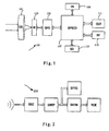
- Fig. 1 depicts a principle block diagram of an infrared thermography system in accordance with the present invention.
- the infrared thermography system 100 comprises an optical system (OS) 101, an infrared radiation (IR) detector 103, a signal preprocessing device (SPD) 105, a signal processing and system control device (SPSCD) 107, an input device (IN) 109, an output (OUT) device 111, a storage device (SD) 113 and a network port (NT) 115.
- OS optical system
- IR infrared radiation
- SPD signal preprocessing device
- SPSCD signal processing and system control device
- INP input device
- OUT output
- SD storage device
- NT network port
- the optical system 101 is used to receive infrared radiation emitted from to be measured objects. It consists of different infrared optical lenses according to different requirements on field of view and image quality, and plays the roles of converging, filtering and focusing infrared radiation of the to be measured objects.
- the infrared radiation detector 103 converts the infrared radiation that has gone through the optical system 101 into electronic signals. It may be an uncooled focal plane array detector (which can be classified into uncooled and cooled types) in which tens of thousands of sensor elements form an array. Each sensor element has relatively fine uniformity of responsivity, micron-measured size and low power consumption.
- uncooled focal plane array detector with 320 ⁇ 240 resolution is utilized.
- uncooled focal plane array detector with 384 ⁇ 288 resolution is utilized, in which the effective pixel ratio increases by 44% over that with 320 ⁇ 240 resolution and the size of a single pixel is much smaller. Therefore, the obtained infrared image or video is even more elegant.
- the signal preprocessing device 105 performs pre-amplification, analog-to-digital (A/D) conversion, and other preprocessing on electronic signals outputted from the infrared radiation detector 103. Accordingly, it can comprise preamplifiers, A/D convertors, etc. (not shown).
- the signal processing and system control device 107 processes the electronic signals that present infrared radiation of the to be measured objects and have been processed by the signal preprocessing device 105 into video signals and then transmits them to the output device 111 used as a display device for display.
- the signal processing and system control device 107 carries out controls corresponding to operators' commands, for example, controlling adjusting image display effect, controlling storage of video images onto the storage device 113, controlling analysis of infrared images, controlling communication with external devices, etc.
- the signal processing and system control device 107 controls the operation of the input device 109, the output device 111, the storage device 113 and the network port 115 to be described below.
- the signal processing and system control device 107 constitutes, in the form of a microprocessor, a component part of the entire infrared thermography system. That is, the signal processing and system control device 107 is embedded into the infrared thermography system.
- an advantage of the present embodiment is that the infrared thermography system is smaller and lighter than the signal processing and system control device 107 as an independent system forms the peripheral equipment of the infrared thermography system.
- the signal processing and system control device 107 processes video signals into VGA (Video Graphics Array) mode that was used as a display mode of computers only.
- VGA Video Graphics Array
- VGA mode can greatly reinforce, in collaboration with a true-color high-brightness TFT LCD that acts as the output device 111, the definition of images.
- VGA display generally requires a special display card.
- the infrared thermography system in accordance with the present invention simplifies the intricate functions of a display card and integrates the simplified functions into itself, and hence, the VGA display output function can be realized without a big-sized display card.
- the signal processing and system control device 107 processes video signals into SVGA (Super Video Graphics Array) mode, thereby a much higher display resolution.
- SVGA Super Video Graphics Array
- the signal processing and system control device 107 further includes a video transform module (not shown), which can transform video signals of VGA mode into those of PAL (Phase Alternating Line) mode or NTSC (National Television Systems Committee) mode to meet requirements of different users.
- a video transform module (not shown), which can transform video signals of VGA mode into those of PAL (Phase Alternating Line) mode or NTSC (National Television Systems Committee) mode to meet requirements of different users.
- the infrared thermography system in accordance with the present invention supports three display modes, i.e., VGA, PAL and NTSC.
- PAL and NTSC are universally adopted in current infrared thermography systems, whereas both with 320 ⁇ 240 resolution, neither of them offers a satisfying display effect.
- the input device 109 is used to input commands and/or corresponding data.
- the corresponding data includes users' annotation of infrared images, etc.
- the input device 109 includes a touch screen (not shown) which is used for receiving users' commands of operation of the infrared thermography system.
- the output device 111 e.g. a display screen
- the signal processing and system control system 107 will immediately perform corresponding operations, resulting in displaying subsidiary operation options, storing video images onto the storage device 113 and communicating with external devices, etc.
- the infrared thermography system in accordance with the present invention greatly facilitates users' operation, enabling users to easily operate the infrared thermography system without bearing in mind some buttons (or combination of buttons) corresponding to operation commands.
- such user-friendly man-machine communication makes it easier for infrared thermography systems to integrate more functions, and even more functions can be implemented by simply clicking the touch screen.
- a further advantage is that with the touch screen, the infrared thermography system is much easier to operate, and accordingly time necessary for operation training is saved.
- the touch screen further acts as the display screen of the output device 111.
- the input device 109 further comprises an automatic speech recognition system.
- Conventional infrared thermography systems must be operated with buttons. However, users cannot operate the systems under certain cases, for example, they get their hands full with the operation of other devices. Taking such situations into account, in the present embodiment of the present invention, the input device 109 of the infrared thermography system includes a function of automatic speech recognition.
- Fig. 2 depicts a working process 200 of automatic speech recognition, which can include processes of speech signal capturing (SSC), signal-noise-reducing preprocessing (SNRP), speech training and template generating (STTG), speech recognizing and template matching (SRTM), and relevant operation executing (ROE) .
- SSC speech signal capturing
- SNRP signal-noise-reducing preprocessing
- STTG speech training and template generating
- SRTM speech recognizing and template matching
- ROE relevant operation executing
- users Before formally using the speech recognition function, users operate the infrared thermography system to capture speech signals for speech training and creating speech templates.
- the created speech templates can be stored onto the storage device 113.
- the infrared thermography system under speech working mode detects speech outside, it will perform speech data processing and template matching so that it can rapidly and accurately respond to the common operation commands given by users, i.e. executing corresponding operations.
- the infrared thermography system in the present embodiment can automatically decide as per the environment whether to perform signal-noise-reducing preprocessing, so as to ensure the accuracy of speech recognition.
- the automatic speech recognition system in the present embodiment includes a microphone for capturing speech signals.
- the microphone is further used for capturing annotation of infrared images as made during the image recording.
- the output device 111 is used for outputting infrared images and/or corresponding data which includes analysis results of infrared images and so on.
- the output device 111 includes a display screen and an eyepiece, all the video images displaying on both of which come from the signal processing and system control device 107.
- the display screen can act as the input device 109 as well, or more specifically, the display screen can be used as the touch screen mentioned above.
- an OLED Organic Light Emitting Display
- OLED Organic Light Emitting Display
- OLED is a new-generation plane display technology after TFT (Thin-Film Technology) liquid crystal display.
- TFT Thin-Film Technology
- Conventional infrared thermography systems generally employ small LCD or CRT (Cathode Ray Tubes) screens as eyepieces, which lead to complicated architecture, large size, intricate circuits and accordingly high power consumption.
- OLED made of very thin coatings of organic materials and glass base plates, will emit light when charges are passing through these organic materials.
- OLED has a thickness of only 1.5mm, which is a bit more than one quarter of the thickness of LCD.
- a refreshing frequency approximately 1000 times higher than that of LCD, it offers smoother and sharper video display.
- a larger viewing angle a maximum of 165 degrees
- the range of its operating temperature is wider than that of LCD, with a lower limit reaching 40°C below zero.
- the output device 111 also includes a voice playback device used for playing back the corresponding annotation stored during playing back the stored infrared video images.
- the storage device 113 is used to store infrared video images and/or corresponding data.
- the corresponding data includes the above mentioned annotation, software for use in control, etc.
- the storage device 113 comprises a Compact Flash (CF) card.
- CF Compact Flash
- the storage device 113 includes a Secure Digital card.
- a Secure Digital card Connected to the infrared thermography system with 9 pins, a Secure Digital card offers a simpler and more reliable interface than CF card that has 50 pins. Secure Digital card has a high read-write speed such that video data can be recorded in real time. Besides a large storage density (the capacity of a single Secure Digitalcard goes up to several G Bytes), Secure Digital card boasts a smaller area and thinner thickness over CF card, thereby being easy to carry.
- the adoption of large-capacity high-speed Secure Digital card lays a foundation for real-time infrared video recording.
- the infrared thermography system in accordance with the present invention further offers a function of infrared video recording, for which different frame frequency can be set to continuously record and store the status of monitored targets.
- the network port 115 is used to communicate with external devices.
- infrared thermography systems can be connected through the network port 115 to form an infrared thermography monitoring network.
- the work of the infrared thermography systems can be remotely monitored.
- all the infrared thermography systems are connected via their respective network ports and network wiring to a host machine located in the remote monitoring room.
- Said host machine may be a computer.
- the host machine can either call an image of a certain infrared thermography system to display or display multi-path images at the same time.
- the host machine can carry out special analyzing and processing of the infrared image (s) . Images captured by each infrared thermography system can be transmitted and exchanged through the network. Therefore, the incorporation of network port enables share of infrared radiation detected resources.
- the network port 115 comprises a Bluetooth port to communicate with external devices that have Bluetooth ports too.
- the network port 115 also includes an Ethernet network port.
- the network port 115 further includes a USB OTG (Universal Serial Bus On-the-Go) port.
- USB OTG Universal Serial Bus On-the-Go
- USB OTG port not only has the conventional USB functions, but also enables infrared thermography systems to be configured as host machines to directly connect with and control other USB devices. In other words, direct connection and data transfer between infrared thermography systems and various other digital devices can be realized even if there is no computer.
- the infrared thermography system in accordance with the present invention can directly connect to printers having USB ports to print analyzed infrared drawings in worksites, or connect to mice having USB ports to operate it under the assistance of high-resolution LCD using VGA display, or even connect to USB storage disks, USB removable hard disks, etc, to enlarge the storage capacity.
- USB OTG port integrated into the infrared thermography system in accordance with the present invention can connect to various USB external devices by loading corresponding drivers, and thus offers a good scalability.
- thermography system in accordance with the present invention utilizes advanced magnalium material as its casing.
- Magnalium material has high rigidity, light weight and good thermal conductivity. Therefore, the infrared thermography system is rugged, reliable, portable, highly electromagnetic shielding and can be better adapted to complex operation environment.
- the present invention provides a new type of infrared thermography system.
- the infrared thermography system integrates multiple advanced technologies and functions, thereby advantages of small volume, light weight, easy operation, excessive functions, good scalability, etc, can be realized.
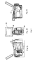
- Fig. 3 depicts a perspective view of an infrared thermography system in accordance with the present invention, wherein Figs. 3A, 3B and 3C are right, back and left views, respectively.
- Fig. 3A illustrates a USB OTG port 301 and an OLED eyepiece 303;
- Fig. 3B illustrates a Bluetooth port 305, an automatic speech recognition system 307 and a touch screen 309 using (used as the display screen as well) VGA display;
- Fig. 3C illustrates a position 311 where a large-capacity SD memory card can be disposed.
- thermography system in accordance with the present invention integrates various functions. That is to say, in the present invention a plurality of advanced technologies and functions are integrated into a single infrared thermography system, thus advantages such as small size, light weight, easy operation, excessive functionality, good scalability, etc, can be realized.
- thermography system includes are presented in a form of schematic view or block diagram to avoid unnecessary details and to facilitate understanding of the present invention.
Landscapes
- General Physics & Mathematics (AREA)
- Physics & Mathematics (AREA)
- Spectroscopy & Molecular Physics (AREA)
- Engineering & Computer Science (AREA)
- Signal Processing (AREA)
- Health & Medical Sciences (AREA)
- Multimedia (AREA)
- Life Sciences & Earth Sciences (AREA)
- Toxicology (AREA)
- Chemical & Material Sciences (AREA)
- Analytical Chemistry (AREA)
- Biochemistry (AREA)
- General Health & Medical Sciences (AREA)
- Immunology (AREA)
- Pathology (AREA)
- Human Computer Interaction (AREA)
- Radiation Pyrometers (AREA)
- Studio Devices (AREA)
- Photometry And Measurement Of Optical Pulse Characteristics (AREA)
Applications Claiming Priority (1)
| Application Number | Priority Date | Filing Date | Title |
|---|---|---|---|
| CNA2005101329731A CN1991317A (zh) | 2005-12-29 | 2005-12-29 | 红外热像仪 |
Publications (1)
| Publication Number | Publication Date |
|---|---|
| EP1804501A1 true EP1804501A1 (fr) | 2007-07-04 |
Family
ID=37845290
Family Applications (1)
| Application Number | Title | Priority Date | Filing Date |
|---|---|---|---|
| EP06018683A Withdrawn EP1804501A1 (fr) | 2005-12-29 | 2006-09-06 | Système de thermographie à infrarouge |
Country Status (4)
| Country | Link |
|---|---|
| US (1) | US20070167830A1 (fr) |
| EP (1) | EP1804501A1 (fr) |
| JP (1) | JP2007184924A (fr) |
| CN (1) | CN1991317A (fr) |
Cited By (1)
| Publication number | Priority date | Publication date | Assignee | Title |
|---|---|---|---|---|
| EP2091238A1 (fr) * | 2008-02-18 | 2009-08-19 | Angela De Donno | Utilisation et création d'images thermographique à des fins artistiques |
Families Citing this family (12)
| Publication number | Priority date | Publication date | Assignee | Title |
|---|---|---|---|---|
| US20100311109A1 (en) * | 2009-06-03 | 2010-12-09 | Salaimeh Ahmad A | Non-contact method for quantifying changes in the dynamics of microbial populations |
| WO2011079208A1 (fr) * | 2009-12-24 | 2011-06-30 | Flir Systems, Inc. | Caméras avec capacités d'élaboration de rapports intégrées |
| WO2011121530A1 (fr) * | 2010-03-31 | 2011-10-06 | International Business Machines Corporation | Procédé, dispositif sécurisé, système et produit-programme informatique destinés à signer numériquement un document |
| KR101246918B1 (ko) * | 2011-09-08 | 2013-03-25 | 유덕봉 | 비접촉식 온도 감시 장치 |
| CN102147291B (zh) * | 2011-03-12 | 2012-06-27 | 福建福光数码科技有限公司 | 中波红外两档视场一体化热成像系统 |
| CN103644973A (zh) * | 2013-12-18 | 2014-03-19 | 江苏省交通科学研究院股份有限公司 | 监测钢结构桥梁路面温度信息的方法、装置及系统 |
| CN104165698A (zh) * | 2014-08-21 | 2014-11-26 | 国家电网公司 | 基于红外热像仪的变电站电力变压器过热故障监测系统 |
| DE102014116160A1 (de) * | 2014-11-06 | 2016-05-12 | Dr. Ing. H.C. F. Porsche Aktiengesellschaft | Turboladeranordnung |
| US9879216B2 (en) * | 2015-12-10 | 2018-01-30 | International Business Machines Corporation | Infrared signal monitoring for cell cultures |
| CN105466568A (zh) * | 2015-12-24 | 2016-04-06 | 何兴扬 | 生命体探测仪及具有该生命体探测仪的飞行器 |
| CN107861034A (zh) * | 2017-10-25 | 2018-03-30 | 国网湖南省电力公司 | 基于图像合成的避雷器、绝缘子缺陷红外成像检测判断方法 |
| CN114397021B (zh) * | 2022-01-21 | 2022-11-01 | 成都市远浩三维科技有限公司 | 一种夜间追踪器及其图像成形方法 |
Citations (8)
| Publication number | Priority date | Publication date | Assignee | Title |
|---|---|---|---|---|
| US5637871A (en) * | 1993-06-07 | 1997-06-10 | Computational Systems, Inc. | Portable digital infrared thermography system |
| EP0992773A2 (fr) * | 1998-10-09 | 2000-04-12 | Thomson-CSF Optronique Canada Inc. | Système non-refroidi pour une visibilité de conduite améliorée |
| EP1028313A2 (fr) * | 1999-02-11 | 2000-08-16 | Flir Systems-Boston Incorporated | Méthode et appareil pour sélectionner des images thermographiques à l'aide de codes-barre |
| US6417797B1 (en) * | 1998-07-14 | 2002-07-09 | Cirrus Logic, Inc. | System for A multi-purpose portable imaging device and methods for using same |
| WO2002090911A1 (fr) * | 2001-05-07 | 2002-11-14 | Flir Systems Ab | Camera infrarouge a main |
| WO2003104877A1 (fr) * | 2002-06-05 | 2003-12-18 | Litton Systems, Inc. | Ensemble lunettes de vision nocturne ameliore |
| US20040114918A1 (en) * | 2002-12-12 | 2004-06-17 | Eastman Kodak Company | Camera having shared optics for optical viewfinding and for electronic capture and display |
| US20050216624A1 (en) * | 2002-09-26 | 2005-09-29 | Guoshun Deng | Device and method for providing data exchange and storage |
Family Cites Families (9)
| Publication number | Priority date | Publication date | Assignee | Title |
|---|---|---|---|---|
| US7640007B2 (en) * | 1999-02-12 | 2009-12-29 | Fisher-Rosemount Systems, Inc. | Wireless handheld communicator in a process control environment |
| JP3674413B2 (ja) * | 1999-10-07 | 2005-07-20 | 日本ビクター株式会社 | 画像撮影装置 |
| US7235785B2 (en) * | 2001-05-11 | 2007-06-26 | Irvine Sensors Corp. | Imaging device with multiple fields of view incorporating memory-based temperature compensation of an uncooled focal plane array |
| US6879954B2 (en) * | 2002-04-22 | 2005-04-12 | Matsushita Electric Industrial Co., Ltd. | Pattern matching for large vocabulary speech recognition systems |
| JP2003344166A (ja) * | 2002-05-24 | 2003-12-03 | Kenji Mitsui | 温度計測用炉内監視システム |
| US20040064315A1 (en) * | 2002-09-30 | 2004-04-01 | Deisher Michael E. | Acoustic confidence driven front-end preprocessing for speech recognition in adverse environments |
| JP2005274301A (ja) * | 2004-03-24 | 2005-10-06 | Mitsubishi Electric Corp | 赤外線カメラ |
| JP2005338359A (ja) * | 2004-05-26 | 2005-12-08 | Constec Engi Co | 撮像装置 |
| US20060104483A1 (en) * | 2004-11-12 | 2006-05-18 | Eastman Kodak Company | Wireless digital image capture device with biometric readers |
-
2005
- 2005-12-29 CN CNA2005101329731A patent/CN1991317A/zh active Pending
-
2006
- 2006-09-06 EP EP06018683A patent/EP1804501A1/fr not_active Withdrawn
- 2006-09-25 US US11/527,241 patent/US20070167830A1/en not_active Abandoned
- 2006-12-27 JP JP2006351851A patent/JP2007184924A/ja active Pending
Patent Citations (8)
| Publication number | Priority date | Publication date | Assignee | Title |
|---|---|---|---|---|
| US5637871A (en) * | 1993-06-07 | 1997-06-10 | Computational Systems, Inc. | Portable digital infrared thermography system |
| US6417797B1 (en) * | 1998-07-14 | 2002-07-09 | Cirrus Logic, Inc. | System for A multi-purpose portable imaging device and methods for using same |
| EP0992773A2 (fr) * | 1998-10-09 | 2000-04-12 | Thomson-CSF Optronique Canada Inc. | Système non-refroidi pour une visibilité de conduite améliorée |
| EP1028313A2 (fr) * | 1999-02-11 | 2000-08-16 | Flir Systems-Boston Incorporated | Méthode et appareil pour sélectionner des images thermographiques à l'aide de codes-barre |
| WO2002090911A1 (fr) * | 2001-05-07 | 2002-11-14 | Flir Systems Ab | Camera infrarouge a main |
| WO2003104877A1 (fr) * | 2002-06-05 | 2003-12-18 | Litton Systems, Inc. | Ensemble lunettes de vision nocturne ameliore |
| US20050216624A1 (en) * | 2002-09-26 | 2005-09-29 | Guoshun Deng | Device and method for providing data exchange and storage |
| US20040114918A1 (en) * | 2002-12-12 | 2004-06-17 | Eastman Kodak Company | Camera having shared optics for optical viewfinding and for electronic capture and display |
Cited By (1)
| Publication number | Priority date | Publication date | Assignee | Title |
|---|---|---|---|---|
| EP2091238A1 (fr) * | 2008-02-18 | 2009-08-19 | Angela De Donno | Utilisation et création d'images thermographique à des fins artistiques |
Also Published As
| Publication number | Publication date |
|---|---|
| CN1991317A (zh) | 2007-07-04 |
| JP2007184924A (ja) | 2007-07-19 |
| US20070167830A1 (en) | 2007-07-19 |
Similar Documents
| Publication | Publication Date | Title |
|---|---|---|
| US20070167830A1 (en) | Infrared thermography system | |
| US7106333B1 (en) | Surveillance system | |
| TW583589B (en) | Passive optical mouse using image sensor with optical dual mode capability | |
| EP3979194A1 (fr) | Procédé et dispositif de détermination d'état d'image, appareil, système et support d'enregistrement informatique | |
| JP5470051B2 (ja) | ノート捕捉装置 | |
| US20190204720A1 (en) | Portable image capture device having handle assembly disposed on main body and portable image capture system using such portable image capture device | |
| US8094242B2 (en) | Object management apparatus, mobile terminal, and object management method | |
| KR20230071720A (ko) | 얼굴 이미지의 랜드마크 좌표 예측 방법 및 장치 | |
| US9602872B2 (en) | Display apparatus and control method thereof | |
| US9876957B2 (en) | Dual mode image sensor and method of using same | |
| DE212010000188U1 (de) | Infrarot-Thermosensor | |
| US20070300091A1 (en) | Computer system and optical pointing device having security function, and security method thereof | |
| WO2019085185A1 (fr) | Stylo intelligent, procédé, dispositif et appareil de commande pour stylo intelligent, et support d'informations | |
| US10663711B2 (en) | Virtual slide stage (VSS) method for viewing whole slide images | |
| US20170019603A1 (en) | Method and photographing apparatus for controlling function based on gesture of user | |
| CN107888833A (zh) | 一种图像拍摄方法及移动终端 | |
| CA2900267A1 (fr) | Systeme et methode de reconnaissance d'objet pour un systeme d'entree interactif | |
| CN100590577C (zh) | 触摸屏定位装置及其定位方法 | |
| JPWO2020085303A1 (ja) | 情報処理装置及び情報処理方法 | |
| CN213958274U (zh) | 一种学习机 | |
| JP3130276U (ja) | 赤外線撮像装置 | |
| JP2018014572A (ja) | 情報処理装置、画像処理システム、プログラム | |
| CN108600623B (zh) | 重聚焦显示方法以及终端设备 | |
| CN117201953A (zh) | 一种图像采集装置 | |
| CN113283420A (zh) | 电子设备、材质检测方法、材质检测装置和可读存储介质 |
Legal Events
| Date | Code | Title | Description |
|---|---|---|---|
| PUAI | Public reference made under article 153(3) epc to a published international application that has entered the european phase |
Free format text: ORIGINAL CODE: 0009012 |
|
| AK | Designated contracting states |
Kind code of ref document: A1 Designated state(s): AT BE BG CH CY CZ DE DK EE ES FI FR GB GR HU IE IS IT LI LT LU LV MC NL PL PT RO SE SI SK TR |
|
| AX | Request for extension of the european patent |
Extension state: AL BA HR MK YU |
|
| 17P | Request for examination filed |
Effective date: 20071002 |
|
| 17Q | First examination report despatched |
Effective date: 20071105 |
|
| AKX | Designation fees paid |
Designated state(s): AT BE BG CH CY CZ DE DK EE ES FI FR GB GR HU IE IS IT LI LT LU LV MC NL PL PT RO SE SI SK TR |
|
| RAP1 | Party data changed (applicant data changed or rights of an application transferred) |
Owner name: WUHAN GUIDE INFRARED CO., LTD. |
|
| RIN1 | Information on inventor provided before grant (corrected) |
Inventor name: HUANG, LI |
|
| STAA | Information on the status of an ep patent application or granted ep patent |
Free format text: STATUS: THE APPLICATION IS DEEMED TO BE WITHDRAWN |
|
| 18D | Application deemed to be withdrawn |
Effective date: 20091223 |