EP1805329B1 - Verfahren zur rückgewinnung von nichtrostendem stahl aus stahlschlacken unter trockenen bedingungen - Google Patents
Verfahren zur rückgewinnung von nichtrostendem stahl aus stahlschlacken unter trockenen bedingungen Download PDFInfo
- Publication number
- EP1805329B1 EP1805329B1 EP05776564A EP05776564A EP1805329B1 EP 1805329 B1 EP1805329 B1 EP 1805329B1 EP 05776564 A EP05776564 A EP 05776564A EP 05776564 A EP05776564 A EP 05776564A EP 1805329 B1 EP1805329 B1 EP 1805329B1
- Authority
- EP
- European Patent Office
- Prior art keywords
- stainless steel
- pieces
- subfraction
- primary
- separator
- Prior art date
- Legal status (The legal status is an assumption and is not a legal conclusion. Google has not performed a legal analysis and makes no representation as to the accuracy of the status listed.)
- Expired - Lifetime
Links
Images

Classifications
-
- C—CHEMISTRY; METALLURGY
- C21—METALLURGY OF IRON
- C21B—MANUFACTURE OF IRON OR STEEL
- C21B3/00—General features in the manufacture of pig-iron
- C21B3/04—Recovery of by-products, e.g. slag
-
- B—PERFORMING OPERATIONS; TRANSPORTING
- B03—SEPARATION OF SOLID MATERIALS USING LIQUIDS OR USING PNEUMATIC TABLES OR JIGS; MAGNETIC OR ELECTROSTATIC SEPARATION OF SOLID MATERIALS FROM SOLID MATERIALS OR FLUIDS; SEPARATION BY HIGH-VOLTAGE ELECTRIC FIELDS
- B03B—SEPARATING SOLID MATERIALS USING LIQUIDS OR USING PNEUMATIC TABLES OR JIGS
- B03B9/00—General arrangement of separating plant, e.g. flow sheets
- B03B9/04—General arrangement of separating plant, e.g. flow sheets specially adapted for furnace residues, smeltings, or foundry slags
-
- B—PERFORMING OPERATIONS; TRANSPORTING
- B03—SEPARATION OF SOLID MATERIALS USING LIQUIDS OR USING PNEUMATIC TABLES OR JIGS; MAGNETIC OR ELECTROSTATIC SEPARATION OF SOLID MATERIALS FROM SOLID MATERIALS OR FLUIDS; SEPARATION BY HIGH-VOLTAGE ELECTRIC FIELDS
- B03C—MAGNETIC OR ELECTROSTATIC SEPARATION OF SOLID MATERIALS FROM SOLID MATERIALS OR FLUIDS; SEPARATION BY HIGH-VOLTAGE ELECTRIC FIELDS
- B03C1/00—Magnetic separation
- B03C1/02—Magnetic separation acting directly on the substance being separated
- B03C1/30—Combinations with other devices, not otherwise provided for
-
- C—CHEMISTRY; METALLURGY
- C22—METALLURGY; FERROUS OR NON-FERROUS ALLOYS; TREATMENT OF ALLOYS OR NON-FERROUS METALS
- C22B—PRODUCTION AND REFINING OF METALS; PRETREATMENT OF RAW MATERIALS
- C22B7/00—Working up raw materials other than ores, e.g. scrap, to produce non-ferrous metals and compounds thereof; Methods of a general interest or applied to the winning of more than two metals
- C22B7/04—Working-up slag
-
- Y—GENERAL TAGGING OF NEW TECHNOLOGICAL DEVELOPMENTS; GENERAL TAGGING OF CROSS-SECTIONAL TECHNOLOGIES SPANNING OVER SEVERAL SECTIONS OF THE IPC; TECHNICAL SUBJECTS COVERED BY FORMER USPC CROSS-REFERENCE ART COLLECTIONS [XRACs] AND DIGESTS
- Y02—TECHNOLOGIES OR APPLICATIONS FOR MITIGATION OR ADAPTATION AGAINST CLIMATE CHANGE
- Y02P—CLIMATE CHANGE MITIGATION TECHNOLOGIES IN THE PRODUCTION OR PROCESSING OF GOODS
- Y02P10/00—Technologies related to metal processing
- Y02P10/20—Recycling
-
- Y—GENERAL TAGGING OF NEW TECHNOLOGICAL DEVELOPMENTS; GENERAL TAGGING OF CROSS-SECTIONAL TECHNOLOGIES SPANNING OVER SEVERAL SECTIONS OF THE IPC; TECHNICAL SUBJECTS COVERED BY FORMER USPC CROSS-REFERENCE ART COLLECTIONS [XRACs] AND DIGESTS
- Y02—TECHNOLOGIES OR APPLICATIONS FOR MITIGATION OR ADAPTATION AGAINST CLIMATE CHANGE
- Y02W—CLIMATE CHANGE MITIGATION TECHNOLOGIES RELATED TO WASTEWATER TREATMENT OR WASTE MANAGEMENT
- Y02W30/00—Technologies for solid waste management
- Y02W30/50—Reuse, recycling or recovery technologies
Definitions
- the invention relates to a method and a device for recovering stainless steel under dry conditions from a waste stream of slags formed in the production of stainless steel in a stainless steel factory.
- the first milling device is in this case a rod mill, the discharge from which is screened to 10-50 mm and 4-10 mm subfractions. These subfractions are discharged as stainless steel concentrates.
- the fraction smaller than 4 mm is pumped into and dewatered in a spiral separator before then being fed to the second milling device.
- the second milling device is in this case a ball mill which operates under wet conditions for final fine-milling of this ultrafine fraction.
- the discharge from the second milling device is treated on a spiral separator in which the largest pieces are discharged as stainless steel concentrate.
- the overflow from the spiral separator is purified in a cyclone prior to treatment on a screen elbow separator for recovering fine stainless steel pieces (1-4 mm).
- the remainder of the waste stream (slurry) is treated in specially sealed settling tanks, in which the excess water is reused for the abovementioned wet milling and screening process.
- FR 2 666 098 discloses a plant for recovering raw materials from special steel slag.
- the plant is used to produce slag that can be employed as a fertilizer for agriculture, with a particle of 0-4 mm.
- the plant performs a density separation of the initial slag, based on a selective classification of this slag by means of screens and pneumatic tables, which are suitable arranged.
- the method comprises the steps of crushing at least part of a waste stream of slags under substantially dry conditions in a primary crushing circuit to form a primary crushed fraction of waste pieces with stainless steel-containing scrap pieces released from the slags, and then screening the primary crushed fraction to form at least a primary coarse and fine subfraction. Then, stainless steel-containing scrap pieces are recovered from the primary coarse subfraction with the aid of a sensor separator.
- the sensor separator in this case measures attenuation of inductances of the waste pieces guided past it, and actuates blowing nozzles as a function of the measured value so as to blow relevant stainless steel-containing scrap pieces out of the primary coarse subfraction guided past the sensor separator.
- the waste pieces which remain after the sensor separation are fed to a magnetic separator, in particular a neodymium magnetic separator, for further recovery of magnetic stainless steel-containing slag pieces.
- a magnetic separator in particular a neodymium magnetic separator
- These magnetic stainless steel-containing slag pieces which have been recovered by the magnetic separator are then returned to a crushing circuit, in particular the abovementioned primary crushing circuit, in order for stainless steel-containing scrap pieces to be released from the slags again.
- This method can give savings of approximately 30% in the further unnecessary treatment of clean slag, i.e. slag which does not contain any stainless steel-containing scrap pieces, and provides a better slag product for reuse.
- the addition of the treatment with the magnetic separator at this point in the method advantageously ensures that the efficiency of the system is considerably improved.
- the sensor separator is then able to take the pure stainless steel out of the waste stream, while the magnetic separator ensures that only slag pieces which contain stainless steel are fed to a crushing circuit or a screen positioned downstream.
- the remainder of the waste stream is formed by slags for reuse.
- This creates a substantially dry recovery process which can make use of crushing techniques without any water having to be supplied, in order to release stainless steel parts so that they can then be separated off by means of sensor separation.
- the quality of the stainless steel scrap recovered in this way is equal to or even greater than that achieved in the prior art, while the capital investment costs required for installing a device for carrying out a method of this type are considerably lower.
- the energy consumption of the method is advantageously low, and a device for carrying out the method can advantageously be of compact construction, and correspondingly can advantageously be delivered in a fixed form or a semi-mobile variant, as desired.
- the method prior to treatment of the primary coarse subfraction with the sensor separator, also comprises the step of recovering magnetic stainless steel-containing scrap pieces therefrom with the aid of a magnetic separator.
- the magnetic separator is then used to remove the ferritic stainless steel-containing scrap pieces, while the sensor separator is used to remove the austenitic stainless steel-containing scrap pieces. This can considerably improve the efficiency of the sensor separation and advantageously relieves the load on the neodymium magnetic separator.
- the invention also relates to a device according to one of claims 20-23, and to the use of a device of this type according to claim 24.
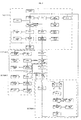
- Section 1 Preliminary separation + treatment with FeSO 4
- a base waste stream of slags (1) derived from the production of stainless steel is mixed with a certain percentage of FeSO 4 (7), for example a few percent, and separated via a grate (2) into a coarse base fraction, for example +250 mm, and a fine base fraction -250 mm.
- the fine base fraction is then separated in a screen (8), for example a rod screen or star screen, into a. plurality of subfractions, for example a subfraction 80-250 mm, a subfraction 10-80 mm and a subfraction 0-10 mm.
- Stainless steel-containing scrap pieces (5) are then visually removed from the coarse base fraction (3), for example with the aid of a hydraulic crane with grab (4).
- the clean coarse base fraction (6) can subsequently be crushed by means of a crusher, for example formed by the same crane, but now with an additional auxiliary tool, such as a jaw crusher, to form a fine base fraction, for example 0-250 mm, and returned to the base waste stream.
- a crusher for example formed by the same crane, but now with an additional auxiliary tool, such as a jaw crusher, to form a fine base fraction, for example 0-250 mm, and returned to the base waste stream.
- One of the subfractions screened out is deferrized in the usual way by means of a magnetic separator (14), in particular a drum magnet, releasing magnetic stainless steel-containing scrap pieces (15).
- the nonmagnetic stainless steel-containing scrap pieces (17) are recovered via a sensor or manual sorting (16).
- a magnetic separator (9), for example a drum magnet, and/or a magnetic separator with neodymium magnet (11) to be positioned on the finest subfraction which is screened out, in order to remove the stainless steel-containing scrap pieces (10 and 12) which are present from it, which scrap pieces are then all returned to section 2, described below.
- the optionally deferrized ultrafine subfraction (13) which has been screened out in this way is discharged as end product.
- the subfraction which had only been screened and the subfraction from which some of the stainless steel-containing scrap pieces had already been removed are returned to section 2 for further processing.
- the treatment with FeSO 4 (7) is carried out in order to convert free Cr 6+ pieces in the waste stream into Cr 3+ , which are nontoxic.
- the intensive treatment of the slag by screening and transfer via various conveyor members, together with the moisture content which is already present in the base waste stream of slags (1), ensure that all the Cr 6+ is converted into Cr 3+ , in accordance with the formula: 2Cr 6+ + 6FeSO 4 2Cr 3+ + 3Fe 2 (SO 4 ) 3 .
- This treatment allows the ultrafine subfraction (13) to be used further according to current environmental rules, for example to be released as a construction material.
- Section 2 Primary crushing circuit
- the subfractions originating from section 1 are in section 2 supplied to a primary crushing circuit (18), in particular an impact crusher (rotary crusher) or a cone crusher or a jaw crusher.
- the subfractions are crushed therein under substantially dry conditions, i.e. without further moisture being supplied.
- the primary crushed fraction formed in this way is then screened in a screen (19), for example a rod screen or linear-eccentric screen, to form a primary coarse subfraction, for example +30 mm, and a primary fine subfraction, for example -30 mm.
- the primary coarse subfraction is deferrized by means of a magnetic separator (20), in particular a drum magnet, and provides magnetic stainless steel-containing scrap pieces (21).
- the nonmagnetic fraction is passed through to a sensor separator (22) for obtaining austenitic stainless steel-containing scrap pieces (23).
- the slag fraction which remains passes through to a neodymium magnetic separator (22a) for recovering slags containing magnetic stainless steel-containing slag pieces, which are then returned to the primary crushing circuit (18) for further release of these included stainless steel-containing scrap pieces in the slags.
- the slag fraction which is not returned to the primary crushing circuit (18) is discharged as slag end product (22b).
- Section 3 Secondary crushing circuit
- the primary fine subfraction which remains in section 2 is passed to a secondary crushing circuit (24), for example a hammer mill, horizontal impactor or vertical shaft impactor, or cone crusher, for further comminution and release of stainless steel-containing scrap pieces from the slag.
- the fraction is there in turn crushed under substantially dry conditions.
- the secondary crushed fraction of waste pieces formed in this way is separated by means of a screen (25) into a plurality of subfractions, for example 10-30 mm, 5-10 mm, 1-5 mm and 0-1 mm.
- the coarsest subfraction of these successively passes via a magnetic separator (26), for example a drum magnet, for obtaining magnetic stainless steel-containing scrap pieces (27), and a sensor separator (28) for obtaining austenitic stainless steel-containing scrap pieces (29).
- the remaining slag fraction is passed to a neodymium magnetic separator (28a) for recovering slags containing magnetic stainless steel-containing slag pieces which are then returned to the secondary crushing circuit (24) for further release of these included stainless steel-containing scrap pieces in the slags.
- the slag fraction which is not returned to the secondary crushing circuit is discharged as slag end product (28b).
- the second-coarsest subfraction of the above likewise passes via a magnetic separator (30), for example a drum magnet, for obtaining magnetic stainless steel-containing scrap pieces (31), and a sensor separator (32) for obtaining austenitic stainless steel-containing scrap pieces (33).
- the remaining slag fraction is returned to the secondary crushing circuit (24) for further release of included stainless steel-containing scrap pieces in the slag.
- the sensor separator may in this case also be followed by a separation using a neodymium magnetic separator in order to efficiently reduce the return flow to the crushing circuit.
- Section 4 Dry milling (milling circuit)
- the second-finest screened subfraction in the screen (25) from section 3 is passed to a magnetic separator (35), in particular a barium ferrite drum magnet, for obtaining magnetic stainless steel-containing scrap pieces (36), the slag fraction is passed to a second magnetic separator (37), in particular a neodymium magnet, for obtaining slightly magnetic stainless steel-containing scrap pieces.
- the remaining slag fraction (38) is returned to the base waste stream (1) for admixing with FeSO 4 , and is ultimately included in the screened-out finest subfraction (13) from section 1. This removal of the "clean" slag (slag which does not contain stainless steel) before it enters a milling circuit (39) saves 20-30% on the milling capacity required.
- the magnetic fraction (36) and the slightly magnetic fraction (37) are together passed to the milling circuit (39), in particular a double vibrating tube mill with rods or eccentric oscillating mill or vertical shaft impactor, which mills the material.
- the milling circuit (39) in particular a double vibrating tube mill with rods or eccentric oscillating mill or vertical shaft impactor, which mills the material.
- the slag will have been milled into dust and after screening in a screen (40), in particular a double-decker screen (sizer), to for example 1 mm, the coarser fraction (1-5 mm) remains as "clean" stainless steel-containing scrap pieces (41). Practical tests have demonstrated that it is in this way possible to achieve a purity of more than 90%.
- the finest screened residual fraction (42) is combined with the finest subtraction (34) which previously remained from section 3, after which the two slag streams are returned to the base waste stream of slags (1) for admixing with FeOS 4 .
- the method provides the following products:
- Fig. 2 shows a variant embodiment of Fig. 1 , in which the same components are denoted by the same reference numerals.
- the major changes lie in particular in section 3 and 4.
- a two-decker screen (25) is now used in section 3, while the magnetic separator (30) and sensor separator (32) have been dispensed with.
- the second-finest screened subfraction from screen (25) from section 3 is passed to a first hopper (50). From this first hopper, this first subfraction passes to a milling circuit (51), which is in this case formed by an impactor, in particular what is known as a vertical shaft impactor, which mills the material. It then passes into a screen (52) which screens it, for example, to 1 mm.
- the finest screened residual fraction is guided past a magnetic separator (53), in particular a neodymium magnetic separator.
- This magnetic separator (52) is, for example, arranged above a vibrating trough, along which the finest screened residual fraction is passed.
- the magnetic separator (52) ensures that stainless steel-containing scrap pieces (54) are removed from it.
- the remaining part is slag (55) which is combined with the finest subfraction (34) which remained from section 3, after which the two slag streams can be returned to the base waste stream of slags (1).
- Section 4 also includes a second hopper (60) which, like the first hopper (50), is connected to the milling circuit (51).
- switchable valves (61, 62) are provided for alternately feeding the milling circuit (51) from the first hopper (50) and the second hopper (60).
- the second hopper (60) is in this case fed by the coarser fraction (1-15 mm) which was screened out by the screen (52) in the first instance.
- the term "in the first instance” is to be understood as meaning the situation in which the milling circuit (51) and therefore also the screen (52) are fed from the first hopper (50).
- the sections can also be used on their own or in other combinations, and it is possible to use other types of crushing devices and screening techniques.
- the coarsenesses to which the crushers crush and the screens screen can be adapted as desired.
- the sensor separators are preferably set in such a manner that they only recover pure stainless steel. It is possible to use various types of magnetic separators and sensor separators.
- the various part-streams which are formed after magnetic separation, sensor separation and/or screening can as desired be discharged directly or temporarily stored and/or returned to any point of the process in order to pass through a number of the substeps of the method again.
- the pretreatment of the waste stream in section 1 can also take place in another manner and/or be completely or partially eliminated.
- section 3 it is also possible for more or fewer subfractions to be treated together by the magnetic separator and the sensor separator in succession.
- the addition of the FeSO 4 may also be omitted or take place elsewhere in the process.
- the invention provides an environmentally friendly recovery process with a high efficiency, allowing advantageous use to be made of crushing, screening and/or milling techniques which are known per se, and also allowing the use of magnetic separators and sensor separators which are known per se. It is a completely dry recovery technique for removing stainless steel-containing scrap pieces with a high purity from the waste stream of steel slag from a stainless steel factory.
Landscapes
- Engineering & Computer Science (AREA)
- Chemical & Material Sciences (AREA)
- Metallurgy (AREA)
- Manufacturing & Machinery (AREA)
- Materials Engineering (AREA)
- Organic Chemistry (AREA)
- Geology (AREA)
- General Life Sciences & Earth Sciences (AREA)
- Environmental & Geological Engineering (AREA)
- Mechanical Engineering (AREA)
- Life Sciences & Earth Sciences (AREA)
- Processing Of Solid Wastes (AREA)
- Manufacture And Refinement Of Metals (AREA)
Claims (24)
- Verfahren zur Rückgewinnung von Edelstahl aus einem Abfallstrom aus Schlacken (1), der während der Herstellung von Edelstahl gebildet wird, mit den folgenden Schritten:- Zerkleinern mindestens eines Teils des Abfallstroms aus Schlacken unter im Wesentlichen trockenen Bedingungen in einem primären Zerkleinerungskreislauf (18) zum Bilden eines primären zerkleinerten Anteils aus Abfallstücken, welcher Edelstahl enthaltende Wertstoffstücke enthält, die aus den Schlacken herausgelöst wurden;- Sieben (19) des primären zerkleinerten Anteils zum Herstellen mindestens eines primären ersten (groben) und eines zweiten (feinen) Unteranteils; und- Rückgewinnen von Wertstoffstücken aus dem primären ersten (groben) Unteranteil mit Hilfe eines Abscheiders;dadurch gekennzeichnet, dass Edelstahl enthaltende Wertstoffstücke aus dem primären ersten (groben) Unteranteil mit Hilfe eines Sensorabscheiders (22) rückgewonnen werden, bei der der Sensorabscheider (22) eine Dämpfung von Induktivitäten der an ihm vorbei geführten Abfallstücke misst, und der Sensorabscheider (22) in Abhängigkeit von der gemessenen Dämpfung der Induktivität Blasdüsen betätigt, um austenitische Edelstahl enthaltende Wertstoffstücke aus dem am Sensorabscheider (22) vorbei geführten primären ersten (groben) Unteranteil herauszublasen,
wobei das Verfahren ferner die folgenden Schritte umfasst:- Zuführen der Abfallstücke des primären ersten (groben) Unteranteils, die nach der Sensor-Abscheidung verbleiben, zu einem Magnetabscheider, zum Rückgewinnen magnetischer Edelstahl enthaltender Schlackestücke; und- Rückführen der magnetischen Edelstahl enthaltenden Schlackestücke, die vom Magnetabscheider (22a) rückgewonnen wurden, an einen Zerkleinerungskreislauf, damit Edelstahl enthaltende Wertstoffstücke erneut aus diesen Schlackestücken gelöst werden können. - Verfahren nach Anspruch 1, wobei die Abfallstücke aus dem primären ersten (groben) Unteranteil, die nach der Sensor-Abscheidung verbleiben, einem Neodym-Magnetabscheider (22a) zugeführt werden, zum Rückgewinnen magnetischer Edelstahl enthaltender Schlackestücke.
- Verfahren nach einem der vorhergehenden Ansprüche, wobei die vom Magnetabscheider (22a) rückgewonnenen magnetischen Edelstahl enthaltenden Schlackestücke zum primären Zerkleinerungskreislauf (18) zurückgeführt werden, damit Edelstahl enthaltende Wertstoffstücke erneut aus diesen Schlackestücken gelöst werden können.
- Verfahren nach einem der vorhergehenden Ansprüche, wobei vor der Behandlung des primären ersten (groben) Unteranteils mit dem Sensorabscheider (22), magnetische Edelstahl enthaltende Wertstoffstücke mit Hilfe eines Magnetabscheiders (20) aus diesem rückgewonnen werden.
- Verfahren nach einem der vorhergehenden Ansprüche, ferner mit den folgenden Schritten:- Zerkleinern des primären zweiten (feinen) Unteranteils unter im Wesentlichen trockenen Bedingungen in einem sekundären Zerkleinerungskreislauf (24) zum Bilden eines sekundären zerkleinerten Anteils aus Abfallstücken, welcher Edelstahl enthaltende Wertstoffstücke enthält, die aus den Schlacken gelöst wurden;- Sieben (25) des sekundären zerkleinerten Anteils zum Bilden mindestens eines sekundären ersten (groben) und eines zweiten (feinen) Unteranteils;- Rückgewinnen Edelstahl enthaltender Wertstoffstücke aus dem sekundären ersten (groben) Unteranteil mit Hilfe eines zweiten Sensorabscheiders (28).
- Verfahren nach Anspruch 5, wobei vor der Behandlung des sekundären ersten (groben) Unteranteils unter der Verwendung des zweiten Sensorabscheiders (28) magnetische Edelstahl enthaltende Wertstoffstücke mit Hilfe eines zweiten Magnetabscheiders (26) aus diesem rückgewonnen werden.
- Verfahren nach Anspruch 5 oder 6, ferner mit den folgenden Schritten:- Zuführen der Abfallstücke des sekundären ersten (groben) Unteranteils, die nach der Sensor-Abscheidung unter der Verwendung des zweiten Sensorabscheiders (28) verbleiben, zu einem zweiten Neodym-Magnetabscheider (22a) zum Rückgewinnen magnetischer Edelstahl enthaltender Schlackestücke; und- Rückführen der magnetischen Edelstahl enthaltenden Schlackestücke, die vom zweiten Neodym-Magnetscheider (22a) rückgewonnen wurden, an den sekundären Zerkleinerungskreislauf (24), damit Edelstahl enthaltende Wertstoffstücke erneut aus diesen Schlackestücken gelöst werden können.
- Verfahren nach einem der vorhergehenden Ansprüche, ferner mit Schritten zur Nachbehandlung (Abschnitt 4) des zweiten (feinen) Unteranteils, nämlich:- Rückgewinnen magnetischer Edelstahl enthaltender Wertstoffstücke aus dem zweiten (feinen) Unteranteil mit Hilfe mindestens eines Magnetabscheiders;- Feinmahlen dieser magnetischen Edelstahl enthaltenden Abfallstücke unter im Wesentlichen trockenen Bedingungen in einem Mahlkreislauf (39) zum Bilden eines gemahlenen Anteils;- Sieben (40) des gemahlenen Anteils zum Bilden mindestens eines ersten (groben) und eines zweiten (feinen) gemahlenen Unteranteils.
- Verfahren nach Anspruch 8, wobei magnetische Edelstahl enthaltende Wertstoffstücke aus dem zweiten (feinen) Unteranteil mit Hilfe mindestens eines Neodym-Magnetabscheiders (37) rückgewonnen werden.
- Verfahren nach Anspruch 8 oder 9, wobei der zweite (feine) gemahlene Unteranteil zum Abfallstrom aus Schlacken zurückgeführt und mit diesem vermischt wird, bevor mindestens ein Teil davon dem primären Zerkleinerungskreislauf (18) zugeführt wird.
- Verfahren nach einem der Ansprüche 8 bis 10, wobei derjenige Teil des sekundären zweiten (feinen) Unteranteils, der nach der magnetischen Trennung verbleibt, zum Abfallstrom aus Schlacken zurückgeführt und mit diesem vermischt wird, bevor mindestens ein Teil davon dem primären Zerkleinerungskreislauf (18) zugeführt wird.
- Verfahren nach einem der vorhergehenden Ansprüche, ferner mit Schritten zur Vorbehandlung (Abschnitt 1) des Abfallstroms, nämlich:- Sieben (8) des Abfallstroms aus Schlacken zum Bilden einer Vielzahl von Unteranteilen;- Zuführen mindestens einer der Unteranteile zu dem primären Zerkleinerungskreislauf (18).
- Verfahren nach Anspruch 12, wobei, bevor der Unteranteil dem primären Zerkleinerungskreislauf (18) zugeführt wird, magnetische Edelstahl enthaltende Wertstoffstücke mit Hilfe eines Magnetabscheiders (9, 14) aus diesem rückgewonnen werden.
- Verfahren nach Anspruch 12 oder 13, wobei, bevor der Unteranteil dem primären Zerkleinerungskreislauf (18) zugeführt wird, austenitische magnetische Edelstahl enthaltende Wertstoffstücke manuell oder mit Hilfe eines Sensorabscheiders (16) aus diesem rückgewonnen werden.
- Verfahren nach einem der vorhergehenden Ansprüche, wobei der Abfallstrom aus Schlacken mit FeSO4 (7) gemischt wird.
- Verfahren nach einem der vorhergehenden Ansprüche, ferner mit Schritten zur Nachbehandlung (Abschnitt 4) des zweiten (feinen) Unteranteils, nämlich:- Feinmahlen des zweiten (feinen) Unteranteils unter im Wesentlichen trockenen Bedingungen in einem Mahlkreislauf (51) zum Bilden eines gemahlenen Anteils;- Sieben (52) des gemahlenen Anteils zum Bilden mindestens eines ersten (groben) und eines zweiten (feinen) gemahlenen Unteranteils;- Rückgewinnen magnetischer Edelstahl enthaltender Abfallstücke (54) aus dem zweiten (feinen) gemahlenen Unteranteil mit Hilfe eines Magnetabscheiders.
- Verfahren nach Anspruch 16, wobei magnetische Edelstahl enthaltende Abfallstücke (54) mit Hilfe eines Neodym-Magnetabscheiders (53) aus dem zweiten (feinen) gemahlenen Unteranteil rückgewonnen werden.
- Verfahren nach Anspruch 16 oder 17, wobei der erste (grobe) gemahlene Unteranteil in den Mahlkreislauf zurückgeführt wird.
- Verfahren nach Anspruch 18, wobei der zweite (feine) Unteranteil (50) und der erste (grobe) gemahlene Unteranteil (60) wechselweise dem Mahlkreislauf (51) zugeführt werden, und wobei nur dann, wenn dem Mahlkreislauf (51) der erste (grobe) gemahlene Unteranteil (60) zugeführt wird, der erste (grobe) gemahlene Unteranteil, der dann ausgesiebt wird, als Edelstahl enthaltende Abfallstücke (65) abgeführt wird.
- Vorrichtung zum Durchführen des Verfahrens nach einem der vorhergehenden Ansprüche, umfassend:- eine Zufuhr zum Bereitstellen eines Abfallstroms aus Schlacken (1), der bei der Herstellung von Edelstahl gebildet wird;- ein primärer Zerkleinerungskreislauf (18) zum Zerkleinern mindestens eines Teils des Abfallstroms aus Schlacken unter im Wesentlichen trockenen Bedingungen zum Bilden eines primären zerkleinerten Anteils aus Abfallstücken, mit Edelstahl enthaltenden Wertstoffstücken, die aus den Schlacken herausgelöst wurden;- ein Sieb (19) zum Sieben des primären zerkleinerten Anteils zum Herstellen mindestens eines primären ersten (groben) und eines zweiten (feinen) Unteranteils; und- einen Abscheider zum Rückgewinnen von Wertstoffstücken aus dem primären ersten (groben) Unteranteil;dadurch gekennzeichnet, dass der Abscheider ein Sensorabscheider (22) ist zum Rückgewinnen Edelstahl enthaltender Wertstoffstücke aus dem primären ersten (groben) Unteranteil, der Sensoren zum Messen einer Dämpfung von Induktivitäten der an ihnen vorbei geführter Abfallstücke und Blasdüsen aufweist, die in Abhängigkeit der von den Sensoren gemessenen Dämpfung von Induktivitäten betätigt werden können, um austenitische Edelstahl enthaltende Wertstoffstücke aus dem primären ersten (groben) Unteranteil, die am Sensorabscheider vorbei geführt wird, heraus zu blasen;- einen Neodym-Magnetabscheider (22a) zum Rückgewinnen magnetischer Edelstahl enthaltender Schlackestücke aus den Abfallstücken des primären ersten (groben) Unteranteils, die nach der Sensor-Abscheidung verbleiben; und- eine Rückführung vom Neodym-Magnetabscheider (22a) an den primären Zerkleinerungskreislauf (18), um erneut Edelstahl enthaltende Wertstoffstücke aus den magnetischen Edelstahl enthaltenden Schlackestücken zu lösen.
- Vorrichtung nach Anspruch 20, umfassend einen Magnetabscheider (20) zum Rückgewinnen magnetischer Edelstahl enthaltender Wertstoffstücke aus dem primären ersten (groben) Unteranteil vor dessen Behandlung durch den Sensorabscheider (22).
- Vorrichtung nach einem der Ansprüche 20 oder 21, weiter mit einem sekundären Zerkleinerungskreislauf (24).
- Vorrichtung nach einem der Ansprüche 20 bis 22, weiter mit einem Mahlkreislauf (39).
- Verwendung einer Vorrichtung nach einem der vorhergehenden Ansprüche zur Rückgewinnung von Edelstahl aus einem Abfallstrom aus Schlacken (1), die bei der Herstellung von Edelstahl in einem Edelstahlwerk gebildet werden.
Applications Claiming Priority (2)
| Application Number | Priority Date | Filing Date | Title |
|---|---|---|---|
| NL1026956A NL1026956C2 (nl) | 2004-09-03 | 2004-09-03 | Werkwijze en inrichting voor het terugwinnen van RVS uit staalslakken. |
| PCT/NL2005/000640 WO2006041281A2 (en) | 2004-09-03 | 2005-09-05 | Method and device for recovering stainless steel from steel slags under dry conditions |
Publications (2)
| Publication Number | Publication Date |
|---|---|
| EP1805329A2 EP1805329A2 (de) | 2007-07-11 |
| EP1805329B1 true EP1805329B1 (de) | 2008-09-24 |
Family
ID=34974253
Family Applications (1)
| Application Number | Title | Priority Date | Filing Date |
|---|---|---|---|
| EP05776564A Expired - Lifetime EP1805329B1 (de) | 2004-09-03 | 2005-09-05 | Verfahren zur rückgewinnung von nichtrostendem stahl aus stahlschlacken unter trockenen bedingungen |
Country Status (5)
| Country | Link |
|---|---|
| EP (1) | EP1805329B1 (de) |
| AT (1) | ATE409239T1 (de) |
| DE (1) | DE602005009967D1 (de) |
| NL (1) | NL1026956C2 (de) |
| WO (1) | WO2006041281A2 (de) |
Cited By (2)
| Publication number | Priority date | Publication date | Assignee | Title |
|---|---|---|---|---|
| US20240091856A1 (en) * | 2020-11-26 | 2024-03-21 | Magsort Oy | Separation of stainless steel slag |
| WO2026093955A1 (en) * | 2024-10-31 | 2026-05-07 | Magaldi Power S.P.A. | System and process for treating slag from waste incineration plants |
Families Citing this family (10)
| Publication number | Priority date | Publication date | Assignee | Title |
|---|---|---|---|---|
| NL1033490C2 (nl) * | 2007-03-05 | 2008-09-08 | Recco B V | Werkwijze voor het scheiden van metaalhoudende delen uit puinhoudende grond. |
| DK2128279T3 (da) * | 2008-05-30 | 2011-07-11 | Recco B V | Fremgangsmåde til adskillelse af metalholdige fraktioner fra tør slagge og anvendelse af denne fremgangsmåde til forbrændingsslaggeaffald |
| NL2001639C2 (nl) * | 2008-05-30 | 2009-12-01 | Recco B V | Werkwijze voor het scheiden van metaalhoudende fracties uit droge slak en gebruik van deze werkwijze voor vuilverbrandingslak. |
| AU2011335037A1 (en) * | 2010-11-29 | 2013-06-13 | Basf Corporation | Magnetic recovery of valuables from slag material |
| US9016477B2 (en) * | 2012-03-19 | 2015-04-28 | Mid-American Gunite, Inc. | Method and system for processing slag material |
| BR102012008340B8 (pt) * | 2012-03-19 | 2022-12-13 | Steel Participacoes E Investimentos S A | Processo e sistema para recuperação a seco de finos e super finos de minério óxido de ferro |
| CN103433125B (zh) * | 2013-03-12 | 2015-04-29 | 沈阳隆基电磁科技股份有限公司 | 冶金渣零排放综合利用工艺 |
| CN108453111A (zh) * | 2017-02-20 | 2018-08-28 | 李国安 | 一种钢渣微粉的生产工艺 |
| CN109706462A (zh) * | 2018-12-27 | 2019-05-03 | 东莞市誉铭新精密技术股份有限公司 | 一种手机天线钢片加工后再次利用的方法 |
| DE102021118108B4 (de) | 2021-07-13 | 2024-09-05 | TSR Recycling GmbH & Co. KG | Verbessertes Verfahren zur Herstellung von Schrottprodukten mit hohem Reinheitsgrad aus inhomogenem Inputmaterial |
Family Cites Families (5)
| Publication number | Priority date | Publication date | Assignee | Title |
|---|---|---|---|---|
| US3885744A (en) * | 1974-05-20 | 1975-05-27 | Air Prod & Chem | Method and apparatus for crushing and separating scrap material |
| DE3644403A1 (de) * | 1986-12-24 | 1988-07-07 | Thomas Holzapfel | Verfahren zur trockenen auftrennung von mehrkomponentigen, aus feststoffbefrachteten rauchgasen, insbesondere von kohleverbrennungsprozessen, stammenden feststoffteilchengemengen |
| ES2025949A6 (es) * | 1990-08-27 | 1992-04-01 | Tratamientos Y Transformacion | Instalacion reucperadora de materias primas a partir de escorias de aceros especiales. |
| NL1016916C2 (nl) * | 2000-12-15 | 2002-07-02 | Univ Delft Tech | Werkwijze en inrichting voor het analyseren en het scheiden van materiaalstromen. |
| EP1312415A1 (de) * | 2001-11-16 | 2003-05-21 | Trading and Recycling Company Sint Truiden | Verfahren zum Gewinnen von rostfrei Stahl aus rostfreien Stahlschlacken |
-
2004
- 2004-09-03 NL NL1026956A patent/NL1026956C2/nl not_active IP Right Cessation
-
2005
- 2005-09-05 AT AT05776564T patent/ATE409239T1/de not_active IP Right Cessation
- 2005-09-05 EP EP05776564A patent/EP1805329B1/de not_active Expired - Lifetime
- 2005-09-05 WO PCT/NL2005/000640 patent/WO2006041281A2/en not_active Ceased
- 2005-09-05 DE DE200560009967 patent/DE602005009967D1/de not_active Expired - Lifetime
Cited By (2)
| Publication number | Priority date | Publication date | Assignee | Title |
|---|---|---|---|---|
| US20240091856A1 (en) * | 2020-11-26 | 2024-03-21 | Magsort Oy | Separation of stainless steel slag |
| WO2026093955A1 (en) * | 2024-10-31 | 2026-05-07 | Magaldi Power S.P.A. | System and process for treating slag from waste incineration plants |
Also Published As
| Publication number | Publication date |
|---|---|
| WO2006041281A8 (en) | 2006-11-09 |
| NL1026956C2 (nl) | 2006-03-06 |
| EP1805329A2 (de) | 2007-07-11 |
| WO2006041281A3 (en) | 2006-06-01 |
| ATE409239T1 (de) | 2008-10-15 |
| WO2006041281A2 (en) | 2006-04-20 |
| DE602005009967D1 (de) | 2008-11-06 |
Similar Documents
| Publication | Publication Date | Title |
|---|---|---|
| CN110694789B (zh) | 一种磁铁矿的选矿方法 | |
| US10118182B2 (en) | Incineration byproduct processing and methods | |
| US11130141B2 (en) | System and method for recovering glass and metal from a mixed waste stream | |
| EP1372860B1 (de) | Anlage und verfahren für die behandlung von metallhaltigem haufwerk | |
| JPS62294140A (ja) | 製鉄所から発生するスラグの処理方法 | |
| CN110624686A (zh) | 一种充分释放磨机能力的磁铁矿选矿工艺 | |
| EP1805329A2 (de) | Verfahren zur rückgewinnung von nichtrostendem stahl aus stahlschlacken unter trockenen bedingungen | |
| CN110339937A (zh) | 一种垃圾焚烧炉渣处理工艺 | |
| CN114226044A (zh) | 一种钢渣除铁工艺 | |
| US20180214891A1 (en) | System and method for recovering desired materials and producing clean aggregate from incinerator ash | |
| CN216499992U (zh) | 一种垃圾焚烧炉渣处理系统 | |
| KR20040104058A (ko) | 건설폐기물을 이용한 양질의 골재 생산장치 및 방법 | |
| JP4563472B2 (ja) | 薄板ガラス原料の製造方法 | |
| CN202516839U (zh) | 炉渣处理装置 | |
| US4276155A (en) | Method for recycling the water used in a process for recovering glass from municipal waste | |
| JP3245549B2 (ja) | 埋め戻し材用砂の製造方法 | |
| CA2418020C (en) | Steel slag processing jig system | |
| CN113976308A (zh) | 一种垃圾焚烧炉渣处理系统及方法 | |
| AU743968B2 (en) | Beneficiation of iron ore waste | |
| CN117399158A (zh) | 一种红磁混合矿选矿工艺及选矿系统 | |
| KR200335865Y1 (ko) | 건설폐기물을 이용한 습식 재생 조골재 및 부순모래제조장치 | |
| CN112090941B (zh) | 一种通用型尾矿综合处理生产线及系统 | |
| KR20030043867A (ko) | 건설폐기물을 이용한 습식 재생 부순모래 제조장치 | |
| JPH04114780A (ja) | コンクリート廃棄物の再処理方法と装置 | |
| KR20040058559A (ko) | 건설폐기물의 재활용을 위한 습식 및 건식 겸용재생골재의 제조방법 및 그 장치 |
Legal Events
| Date | Code | Title | Description |
|---|---|---|---|
| PUAI | Public reference made under article 153(3) epc to a published international application that has entered the european phase |
Free format text: ORIGINAL CODE: 0009012 |
|
| 17P | Request for examination filed |
Effective date: 20070319 |
|
| AK | Designated contracting states |
Kind code of ref document: A2 Designated state(s): AT BE BG CH CY CZ DE DK EE ES FI FR GB GR HU IE IS IT LI LT LU LV MC NL PL PT RO SE SI SK TR |
|
| DAX | Request for extension of the european patent (deleted) | ||
| GRAP | Despatch of communication of intention to grant a patent |
Free format text: ORIGINAL CODE: EPIDOSNIGR1 |
|
| GRAS | Grant fee paid |
Free format text: ORIGINAL CODE: EPIDOSNIGR3 |
|
| GRAA | (expected) grant |
Free format text: ORIGINAL CODE: 0009210 |
|
| RIN1 | Information on inventor provided before grant (corrected) |
Inventor name: GROOTHOFF, JAN, ANDREAS Inventor name: VAN LOOY, ERIC Inventor name: HOOIVELD, JAN |
|
| AK | Designated contracting states |
Kind code of ref document: B1 Designated state(s): AT BE BG CH CY CZ DE DK EE ES FI FR GB GR HU IE IS IT LI LT LU LV MC NL PL PT RO SE SI SK TR |
|
| REG | Reference to a national code |
Ref country code: GB Ref legal event code: FG4D |
|
| REG | Reference to a national code |
Ref country code: CH Ref legal event code: EP |
|
| REG | Reference to a national code |
Ref country code: IE Ref legal event code: FG4D |
|
| REF | Corresponds to: |
Ref document number: 602005009967 Country of ref document: DE Date of ref document: 20081106 Kind code of ref document: P |
|
| REG | Reference to a national code |
Ref country code: SE Ref legal event code: TRGR |
|
| PG25 | Lapsed in a contracting state [announced via postgrant information from national office to epo] |
Ref country code: LT Free format text: LAPSE BECAUSE OF FAILURE TO SUBMIT A TRANSLATION OF THE DESCRIPTION OR TO PAY THE FEE WITHIN THE PRESCRIBED TIME-LIMIT Effective date: 20080924 |
|
| PG25 | Lapsed in a contracting state [announced via postgrant information from national office to epo] |
Ref country code: LV Free format text: LAPSE BECAUSE OF FAILURE TO SUBMIT A TRANSLATION OF THE DESCRIPTION OR TO PAY THE FEE WITHIN THE PRESCRIBED TIME-LIMIT Effective date: 20080924 Ref country code: SI Free format text: LAPSE BECAUSE OF FAILURE TO SUBMIT A TRANSLATION OF THE DESCRIPTION OR TO PAY THE FEE WITHIN THE PRESCRIBED TIME-LIMIT Effective date: 20080924 |
|
| PG25 | Lapsed in a contracting state [announced via postgrant information from national office to epo] |
Ref country code: BE Free format text: LAPSE BECAUSE OF FAILURE TO SUBMIT A TRANSLATION OF THE DESCRIPTION OR TO PAY THE FEE WITHIN THE PRESCRIBED TIME-LIMIT Effective date: 20080924 |
|
| PG25 | Lapsed in a contracting state [announced via postgrant information from national office to epo] |
Ref country code: BG Free format text: LAPSE BECAUSE OF FAILURE TO SUBMIT A TRANSLATION OF THE DESCRIPTION OR TO PAY THE FEE WITHIN THE PRESCRIBED TIME-LIMIT Effective date: 20081224 Ref country code: ES Free format text: LAPSE BECAUSE OF FAILURE TO SUBMIT A TRANSLATION OF THE DESCRIPTION OR TO PAY THE FEE WITHIN THE PRESCRIBED TIME-LIMIT Effective date: 20090104 |
|
| PG25 | Lapsed in a contracting state [announced via postgrant information from national office to epo] |
Ref country code: SK Free format text: LAPSE BECAUSE OF FAILURE TO SUBMIT A TRANSLATION OF THE DESCRIPTION OR TO PAY THE FEE WITHIN THE PRESCRIBED TIME-LIMIT Effective date: 20080924 Ref country code: IS Free format text: LAPSE BECAUSE OF FAILURE TO SUBMIT A TRANSLATION OF THE DESCRIPTION OR TO PAY THE FEE WITHIN THE PRESCRIBED TIME-LIMIT Effective date: 20090124 Ref country code: CZ Free format text: LAPSE BECAUSE OF FAILURE TO SUBMIT A TRANSLATION OF THE DESCRIPTION OR TO PAY THE FEE WITHIN THE PRESCRIBED TIME-LIMIT Effective date: 20080924 Ref country code: RO Free format text: LAPSE BECAUSE OF FAILURE TO SUBMIT A TRANSLATION OF THE DESCRIPTION OR TO PAY THE FEE WITHIN THE PRESCRIBED TIME-LIMIT Effective date: 20080924 Ref country code: PT Free format text: LAPSE BECAUSE OF FAILURE TO SUBMIT A TRANSLATION OF THE DESCRIPTION OR TO PAY THE FEE WITHIN THE PRESCRIBED TIME-LIMIT Effective date: 20090224 |
|
| PG25 | Lapsed in a contracting state [announced via postgrant information from national office to epo] |
Ref country code: DK Free format text: LAPSE BECAUSE OF FAILURE TO SUBMIT A TRANSLATION OF THE DESCRIPTION OR TO PAY THE FEE WITHIN THE PRESCRIBED TIME-LIMIT Effective date: 20080924 Ref country code: EE Free format text: LAPSE BECAUSE OF FAILURE TO SUBMIT A TRANSLATION OF THE DESCRIPTION OR TO PAY THE FEE WITHIN THE PRESCRIBED TIME-LIMIT Effective date: 20080924 |
|
| PLBE | No opposition filed within time limit |
Free format text: ORIGINAL CODE: 0009261 |
|
| STAA | Information on the status of an ep patent application or granted ep patent |
Free format text: STATUS: NO OPPOSITION FILED WITHIN TIME LIMIT |
|
| PG25 | Lapsed in a contracting state [announced via postgrant information from national office to epo] |
Ref country code: IT Free format text: LAPSE BECAUSE OF FAILURE TO SUBMIT A TRANSLATION OF THE DESCRIPTION OR TO PAY THE FEE WITHIN THE PRESCRIBED TIME-LIMIT Effective date: 20080924 |
|
| 26N | No opposition filed |
Effective date: 20090625 |
|
| PG25 | Lapsed in a contracting state [announced via postgrant information from national office to epo] |
Ref country code: MC Free format text: LAPSE BECAUSE OF NON-PAYMENT OF DUE FEES Effective date: 20090930 |
|
| REG | Reference to a national code |
Ref country code: CH Ref legal event code: PL |
|
| EUG | Se: european patent has lapsed | ||
| GBPC | Gb: european patent ceased through non-payment of renewal fee |
Effective date: 20090905 |
|
| PG25 | Lapsed in a contracting state [announced via postgrant information from national office to epo] |
Ref country code: PL Free format text: LAPSE BECAUSE OF FAILURE TO SUBMIT A TRANSLATION OF THE DESCRIPTION OR TO PAY THE FEE WITHIN THE PRESCRIBED TIME-LIMIT Effective date: 20080924 |
|
| REG | Reference to a national code |
Ref country code: IE Ref legal event code: MM4A |
|
| PG25 | Lapsed in a contracting state [announced via postgrant information from national office to epo] |
Ref country code: IE Free format text: LAPSE BECAUSE OF NON-PAYMENT OF DUE FEES Effective date: 20090905 |
|
| PGFP | Annual fee paid to national office [announced via postgrant information from national office to epo] |
Ref country code: NL Payment date: 20100215 Year of fee payment: 5 |
|
| PG25 | Lapsed in a contracting state [announced via postgrant information from national office to epo] |
Ref country code: LI Free format text: LAPSE BECAUSE OF NON-PAYMENT OF DUE FEES Effective date: 20090930 Ref country code: CH Free format text: LAPSE BECAUSE OF NON-PAYMENT OF DUE FEES Effective date: 20090930 |
|
| PG25 | Lapsed in a contracting state [announced via postgrant information from national office to epo] |
Ref country code: GB Free format text: LAPSE BECAUSE OF NON-PAYMENT OF DUE FEES Effective date: 20090905 Ref country code: AT Free format text: LAPSE BECAUSE OF NON-PAYMENT OF DUE FEES Effective date: 20090905 |
|
| REG | Reference to a national code |
Ref country code: NL Ref legal event code: V1 Effective date: 20110401 |
|
| PG25 | Lapsed in a contracting state [announced via postgrant information from national office to epo] |
Ref country code: LU Free format text: LAPSE BECAUSE OF NON-PAYMENT OF DUE FEES Effective date: 20090905 |
|
| PG25 | Lapsed in a contracting state [announced via postgrant information from national office to epo] |
Ref country code: SE Free format text: LAPSE BECAUSE OF NON-PAYMENT OF DUE FEES Effective date: 20090906 |
|
| PG25 | Lapsed in a contracting state [announced via postgrant information from national office to epo] |
Ref country code: HU Free format text: LAPSE BECAUSE OF FAILURE TO SUBMIT A TRANSLATION OF THE DESCRIPTION OR TO PAY THE FEE WITHIN THE PRESCRIBED TIME-LIMIT Effective date: 20090325 |
|
| PG25 | Lapsed in a contracting state [announced via postgrant information from national office to epo] |
Ref country code: TR Free format text: LAPSE BECAUSE OF FAILURE TO SUBMIT A TRANSLATION OF THE DESCRIPTION OR TO PAY THE FEE WITHIN THE PRESCRIBED TIME-LIMIT Effective date: 20080924 Ref country code: NL Free format text: LAPSE BECAUSE OF NON-PAYMENT OF DUE FEES Effective date: 20110401 |
|
| PG25 | Lapsed in a contracting state [announced via postgrant information from national office to epo] |
Ref country code: CY Free format text: LAPSE BECAUSE OF FAILURE TO SUBMIT A TRANSLATION OF THE DESCRIPTION OR TO PAY THE FEE WITHIN THE PRESCRIBED TIME-LIMIT Effective date: 20080924 |
|
| PGFP | Annual fee paid to national office [announced via postgrant information from national office to epo] |
Ref country code: FR Payment date: 20111010 Year of fee payment: 7 |
|
| PGFP | Annual fee paid to national office [announced via postgrant information from national office to epo] |
Ref country code: FI Payment date: 20120326 Year of fee payment: 7 |
|
| PGFP | Annual fee paid to national office [announced via postgrant information from national office to epo] |
Ref country code: DE Payment date: 20120327 Year of fee payment: 7 |
|
| PG25 | Lapsed in a contracting state [announced via postgrant information from national office to epo] |
Ref country code: FI Free format text: LAPSE BECAUSE OF NON-PAYMENT OF DUE FEES Effective date: 20120905 |
|
| REG | Reference to a national code |
Ref country code: FR Ref legal event code: ST Effective date: 20130531 |
|
| REG | Reference to a national code |
Ref country code: DE Ref legal event code: R119 Ref document number: 602005009967 Country of ref document: DE Effective date: 20130403 |
|
| PG25 | Lapsed in a contracting state [announced via postgrant information from national office to epo] |
Ref country code: DE Free format text: LAPSE BECAUSE OF NON-PAYMENT OF DUE FEES Effective date: 20130403 |
|
| PG25 | Lapsed in a contracting state [announced via postgrant information from national office to epo] |
Ref country code: FR Free format text: LAPSE BECAUSE OF NON-PAYMENT OF DUE FEES Effective date: 20121001 |
|
| PG25 | Lapsed in a contracting state [announced via postgrant information from national office to epo] |
Ref country code: GR Free format text: LAPSE BECAUSE OF FAILURE TO SUBMIT A TRANSLATION OF THE DESCRIPTION OR TO PAY THE FEE WITHIN THE PRESCRIBED TIME-LIMIT Effective date: 20080924 |