EP1805907B1 - Systeme et procede pour surveillance une impedance - Google Patents
Systeme et procede pour surveillance une impedance Download PDFInfo
- Publication number
- EP1805907B1 EP1805907B1 EP05797377A EP05797377A EP1805907B1 EP 1805907 B1 EP1805907 B1 EP 1805907B1 EP 05797377 A EP05797377 A EP 05797377A EP 05797377 A EP05797377 A EP 05797377A EP 1805907 B1 EP1805907 B1 EP 1805907B1
- Authority
- EP
- European Patent Office
- Prior art keywords
- port
- impedance
- plc
- monitoring
- ports
- Prior art date
- Legal status (The legal status is an assumption and is not a legal conclusion. Google has not performed a legal analysis and makes no representation as to the accuracy of the status listed.)
- Expired - Lifetime
Links
Images




Classifications
-
- H—ELECTRICITY
- H04—ELECTRIC COMMUNICATION TECHNIQUE
- H04B—TRANSMISSION
- H04B3/00—Line transmission systems
- H04B3/54—Systems for transmission via power distribution lines
- H04B3/56—Circuits for coupling, blocking, or by-passing of signals
-
- H—ELECTRICITY
- H04—ELECTRIC COMMUNICATION TECHNIQUE
- H04B—TRANSMISSION
- H04B3/00—Line transmission systems
- H04B3/54—Systems for transmission via power distribution lines
-
- H—ELECTRICITY
- H04—ELECTRIC COMMUNICATION TECHNIQUE
- H04B—TRANSMISSION
- H04B2203/00—Indexing scheme relating to line transmission systems
- H04B2203/54—Aspects of powerline communications not already covered by H04B3/54 and its subgroups
- H04B2203/5462—Systems for power line communications
- H04B2203/5495—Systems for power line communications having measurements and testing channel
Definitions
- This invention relates to an impedance monitoring system and method for applications in utility supply, telecommunications, remote sensing, radar, electronics etc; and more particularly to a system and method for monitoring in real time power line carrier (PLC) impedance on a live or passive high voltage (HV) over head transmission line (OHTL).
- PLC power line carrier
- HV live or passive high voltage
- OHTL head transmission line
- a PLC system operates to transmit and receive signals in a wide frequency band which may typically be 50kHz to 500kHz over an HV OHTL, while the line is carrying the normal 50 Hz mains power.
- the PLC signal is injected and retrieved from the OHTL.
- a PLC system is mainly used to communicate protection control signals (such as a tripping tone etc) for the apparatus as well as data and speech signals.
- the PLC system comprises a PLC transceiver; a phase combiner or hybrid, if coupling to more than one phase of the line is required; line matching units; coupling capacitors or capacitor voltage transformers; the OHTL and line traps in the line.
- the line trap is a known filtering device and is located in a phase of the OHTL between the coupling capacitors or capacitator voltage transformer and the substation to provide a high impedance in the PLC frequency band and thereby to prevent the coupled signal from being shorted out by the sub-station apparatus. Therefore, most of the PLC energy is channeled to propagate on the OHTL phases to a second remote sub-station connected to the line.
- a PLC based system and method of monitoring sag of an OHTL there is disclosed a PLC based system and method of monitoring sag of an OHTL.
- a system and method of monitoring and/or measuring in real time the impedance associated with the line may facilitate the sag monitoring.
- a method of monitoring the impedance may also be used to monitor the condition of the line as aforesaid and to optimize operation and utilization of the line.
- a method and system of monitoring the impedance associated with the line could facilitate matching of peripheral equipment to the line.
- the invention is a system as defined in Claim 1 and a method as defined in claim 12.
- the term “monitoring” is used to include within its scope “measuring”, whereby a complex value of the impedance is determined.
- the term “impedance” is used to denote the ratio of a voltage phasor and a current phaser at frequencies of interest.
- the term “alternating signal” is used to include within its scope a fixed frequency continuous wave (CW) signal, a stepped frequency continuous wave (SFCW) signal and any other alternating signal having a suitable waveform.
- the impedance may be that of any electrical system, apparatus, device, component, conductor or line, including a phase conductor of an overhead power transmission line.
- the impedance of a phase conductor may be attributable to the OHTL geometry, including average sag, and/or a sub-station at one or both ends of the OHTL and/or a phase conductor line trap and/or other PLC component and/or other HV system components.
- the phase conductor may be connectable to the first port by a suitable signal transmission line, such as a coaxial cable and coupling equipment.
- the coupling equipment may comprise a line matching unit and one of a coupling capacitor and capacitor voltage transformer.
- the monitoring power coupling device may comprise a power splitter and combiner.
- the power splitter and combiner may comprise a hybrid comprising a transformer providing the first, second and third ports.
- the impedance being monitored may be the impedance presented by the line to a power line carrier (PLC) signal and which PLC signal is injected on the line by a PLC system.
- PLC power line carrier
- the first port may be terminated by the impedance to be monitored and the second and third ports are preferably terminated by or connected to respective impedances, each of which is substantially equal to a characteristic impedance of the PLC system.
- the first port of the monitoring power coupling device is connected to a first phase conductor of the OHTL;
- the PLC system may comprise a PLC power coupling device having a first port, a second port and a third port, and a PLC transceiver connected to the first port of the PLC power coupling device, the second port of the PLC power coupling device being connected to a second phase conductor of the OHTL and the third port of the PLC power coupling device being connected to the second port of the monitoring power coupling device to cause the PLC transceiver to drive the second port of the monitoring power coupling device.
- the first port of the monitoring power coupling device is connected to a first phase conductor of the OHTL and the third port of the monitoring power coupling device is connected to a signal generator to drive the third port.
- Variations in the isolation may be monitored by monitoring a ratio of voltages at the third and second ports.
- the ratio is preferably a complex ratio.
- the impedance monitoring arrangement may be portable and the first port may be connectable to any phase conductor of an HV OHTL, to measure impedance in a PLC frequency band presented by the phase conductor.
- the arrangement may be configured to be used as a line trap or other PLC component tester, to test a line trap in the phase conductor or any other defective components of the PLC system.
- figure 1 is a block diagram of a known PLC system connected to a multi-phase overhead transmission line (OHTL);
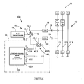
- FIG. 1 A block diagram of a known PLC system 100 connected to a three phase high voltage (HV), typically 400 kV, overhead transmission line (OHTL) 12 is shown in figure 1 .
- HV high voltage
- OHTL overhead transmission line
- the OHTL 12 comprises a centre phase conductor 12.2 and two outer phase conductors 12.1 and 12.3 respectively.
- the OHTL extends between spaced dead end structures such as a first sub-station 11 and a second sub-station 13. Between the dead end structures, the OHTL is supported in known manner by spaced suspension towers (not shown).
- the PLC system 100 comprises first and second similar parts 102 and 104 located at the first and second sub-stations 11 and 13, respectively. Since the parts are similar in configuration, only the first part 102 will be described.
- the first part comprises a known PLC transceiver 14 connected to a first port 16.1 of a known PLC power coupling device or power splitter/combiner 16.
- Second and third ports 16.2 and 16.3 of the splitter/combiner are connected in known manner via line matching units (LMU) 18 and 20 and coupling capacitors 22 and 24 to inner and outer phase conductors 12.2 and 12.1 respectively of the OHTL 12.
- LMU line matching units
- the transceiver 14 and splitter/combiner 16 are typically located in a control room 26 at the first sub-station 11 and the line matching units, coupling capacitors and line traps (LT) are located in a HV yard 28 at the first sub-station 11.
- the LMU 18 comprises a known passive matching transformer, which matches the impedance of the OHTL (which is typically about 350 ohm in the PLC frequency band) to the design characteristic impedance Z o of the PLC system, which will be taken to be 75 ohms throughout, but may differ depending on the specific PLC system.
- the splitter acts as a phase combiner.
- the splitter/combiner 16 is preferably in the form of a hybrid 30 (shown in figure 3 ) comprising a known low insertion loss three-port transformer 32, which is wound in such a way that signals received at a first port of the hybrid are essentially equal to the sum of signals delivered at second and third ports of the hybrid. Differential mode signals received at the second and third ports are summed at the first port, while common mode signals received at the second and third ports are delivered to an internal isolation impedance Z hybrid, but not to the first port.
- signals transmitted by a PLC transceiver 14 are divided to drive the two phase conductors 12.1 and 12.2 of the OHTL as hereinbefore described, usually in anti-phase and differential mode signals received from the OHTL are combined at the hybrid 16 and delivered to the PLC transceiver.
- Z 1 in figure 3 represents the impedance of the PLC transceiver 14, which is designed to be as close as possible to the characteristic impedance Z o of 75 ohm at the operating frequency and Z 2 and Z 3 are impedances of the PLC system on the OHTL, also about 75 ohm each.
- the impedance monitoring system 10 comprises a second and similar hybrid 40 having a first port 40.1, a second port 40.2 and a third port 40.3.
- the first port 40.1 is connected via a signal transmission line in the form of a coaxial cable and LMU 20 to the aforementioned outer phase 12.1 of the OHTL.
- the second port 40.2 is connected to both the third port 16.3 of the first hybrid 16 and a first input port 42.1 of an impedance monitoring logging device 42 with associated signal generator.
- the third port 40.3 of the second hybrid is terminated in a third port 42.3 of the logging device 42, which port 42.3 is associated with the signal generator and is designed to have a 75 ohm output impedance.
- This port 42.3 is also connected to a second port 42.2 of the impedance monitoring logging device 42.
- the input ports 42.1 and 42.2 of the monitoring logging device 42 have high input impedances.
- hybrid 16 is used in the conventional configuration, but hybrid 40 not.
- each of the hybrids 16 and 40 has a winding ratio between the first port (N 1 ) to the second port (N 2 ) of square root (2).
- the winding ratio between the first port (N 1 ) and the third port (N 3 ) is also square root (2).
- Z_hybrid 36 is an impedance, which is chosen at Z 0 2 , to achieve good isolation between the second and third ports of the hybrid.
- a suitable hybrid that may be used is the type A9BM manufactured by ABB Powertech.
- V ⁇ g V g ⁇ e j ⁇ g ⁇ t
- V ⁇ g ⁇ 2 V g ⁇ 2 ⁇ e j ⁇ g ⁇ 2 ⁇ e j ⁇ g ⁇ t
- V ⁇ g ⁇ 3 V g ⁇ 3 ⁇ e j ⁇ g ⁇ 3 ⁇ e j ⁇ g ⁇ t
- the PLC impedance of the phases 12.1 and/or 12.2 can be monitored and/or tracked and/or measured in real time.
- the second port 40.2 and third port 40.3 of the second hybrid 40 are well terminated in the system characteristic impedance via the PLC carrier system and output impedance at port 42.3 respectively. Variations in the phase impedance presented at second port 16.2 of the first hybrid 16 do not cause significant system impedance variations at third port 16.3 of the first hybrid 16, due to the intrinsic isolation of the first hybrid.
- the first port 40.1 of the second hybrid 40 is connected to the phase conductor 12.1, to monitor the PLC impedance as aforesaid.
- the PLC impedance may be monitored as aforesaid at the carrier frequency (typically but not exclusively 50kHz to 500kHz) of the PLC system, utilizing the PLC transceiver as signal source.
- the generator associated with logging device 42 is switched off, but port 40.3 is still terminated in the output impedance of port 42.3 of 75ohm.
- the power of the tone is divided at the first hybrid 16 between the second and third ports 16.2 and 16.3. Referring only to the outer phase conductor 12.1, power leaving port 16.3 is injected at second port 40.2 of the second hybrid 40, which in turn is coupled to the outer phase 12.1 of the OHTL 12 via first port 40.1.
- the monitoring logging device 42 samples and/or measures instantaneous voltages V ⁇ g 2 and V ⁇ g 3 at second port 40.2 and third port 40.3, and uses standard and known techniques (such as I and Q component decomposition) to determine the relative amplitude and relative phase of V ⁇ g 2 / V ⁇ g 3 of the signals at the third and second ports, to measure the aforementioned complex isolation. From this complex isolation, the PLC impedance at the carrier frequencies can be computed.
- the monitoring logging device 42 may comprise a very fast sampling device in the time domain, which could compute the magnitude and phase of the signal in various ways known to the person skilled in the art.
- the PLC impedance may be monitored at other user selectable frequencies in the PLC band.
- the tone V ⁇ g is generated with a selected frequency by the generator forming part of monitoring logging device 42 and is coupled to the OHTL 12.
- the generator output at 42.3 has an output impedance of 75 ohm.
- the complex isolation is determined as hereinbefore described, to compute the PLC impedance at the selected frequency.
- the PLC impedance of the phase conductor 12.1 may be monitored in real time, while the OHTL may still be carrying the 50 Hz mains power.
- the second hybrid 40 and logging device 42 with associated generator may form part of a mobile and portable test arrangement or unit, which may in some embodiments specially be configured to perform tests on line traps or other PLC component in the OHTL.
- the unit may be connected to the PLC system as hereinbefore described in the aforementioned control room 26 of the first sub-station 11.
- Figure 4 illustrates the variation in the isolation magnitude in dB as a function of Z 1 where Z 1 is real only.
- figures 5 and 6 illustrate the real part of the isolation and the imaginary part respectively. Again it is clear that the system and method is suitably sensitive when the real part of the monitored impedance is close to 75 ohms and the imaginary part is small.
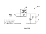
- the outer phase conductor 12.1, to which the impedance monitoring system 10 is coupled in figure 2 can be represented as in figure 7 .
- the coupling capacitor or CVT can be simplified with a short circuit, as the capacitor provides a low impedance path for the signals to be coupled to the OHTL 12.
- the impedance Ztm of the transmission line 12 In a normal operating PLC system, mainly two major impedances can vary, the impedance Ztm of the transmission line 12 and the impedance Zs of the power or sub-station 11.
- the impedance Zlt of the line trap is fixed and should not vary under normal operating conditions, unless it is damaged. It is known that the impedance Ztm of the transmission line normally varies with a day-night cycle as the geometry of the conductor changes, primarily due to sag.
- the power station impedance Zs variations are commonly more dramatic, as station equipment (like transformers) is switched between various states. Therefore, it has an unpredictable step-like nature even under normal operating conditions.
- These variations in these impedances are transformed via the LMU 20, to vary in the region of 75 ohm.
- the impedance monitoring system and method according to the invention are most sensitive at 75 ohm and therefore changes in transmission line impedance Ztm, power station impedance Zs and line trap impedance Zlt can be observed.
- the system according to the invention may be permanently or semi-permanently installed at a sub-station and used to monitor the PLC impedance of the phase conductor continuously over a period of time.
- the portable arrangement according to the invention may be connected to the line to monitor and measure in real time the impedance of the phase conductor, before the arrangement is disconnected and removed.
- FIG 8 there is shown a diagram of the voltage at third port 40.3 of second hybrid 40 in figure 2 , as logged over a period of one week at a local carrier frequency, thus the signal generator of logging device 42 was switched off, but not disconnected.
- This graph contains valuable information about the PLC impedance of the OHTL 12, power or sub-station impedance and the PLC equipment impedance. A clear day-night cycle can be observed within the data, which may relate to the height variation of the line.
- PLC based line sag monitoring systems which systems measure the average conductor height by monitoring specially coupled PLC sag monitoring tones coupled to the line.
- the real-time PLC system impedance as obtained with the system and method according to the invention is a critical parameter to have available while operating the PLC based sag monitoring system. It is known that the OHTL transmission line impedance is a function of OHTL sag.
- Measurement of the OHTL impedance may therefore be related to OHTL sag, and this information could be utilized to assist in the PLC sag monitoring systems and methods.
- step changes at either station at the ends of the OHTL may result in a small step change in the signal level of the PLC sag monitoring tones, which may result in uncalibrated PLC sag monitoring system operation, ie unacceptable errors in the relationship between PLC signal amplitude and OHTL sag.
- the effect of substation switching or any other event that changes the substation impedance may be compensated for in the PLC sag monitoring system.
- Critical PLC components like line traps fail with time, like any other equipment in a harsh electrical environment.
- the PLC system is designed to be still operational, even if one component, for example a line trap, or more specifically a tuning unit of a line trap, is defective. This philosophy makes it difficult to maintain the PLC system.
- currently routine maintenance has to be scheduled to check the functioning of PLC components.
- the system and method according to the invention may be used to detect defective components, such as a defective LMU or a defective line trap or a coupling capacitor (CC) or capacitor voltage transformer (CVT) Even if the method according to the invention is not used in real time, it may be used to speed up the maintenance process.
- the portable test unit comprising the second hybrid 40 and logging device 42 may be configured to constitute a line trap tester.
- the tester is connectable to the PLC system as hereinbefore described and a defective line trap may be detected from the control room 26 while the HV power network may be operational.
- impedance matching of the PLC system to the impedance of the OHTL is very important.
- the system and method according to the invention may be used to optimise impedance matching of the PLC system.
Landscapes
- Engineering & Computer Science (AREA)
- Power Engineering (AREA)
- Computer Networks & Wireless Communication (AREA)
- Signal Processing (AREA)
- Cable Transmission Systems, Equalization Of Radio And Reduction Of Echo (AREA)
- Arrangements For Transmission Of Measured Signals (AREA)
- Emergency Alarm Devices (AREA)
- Alarm Systems (AREA)
- Remote Monitoring And Control Of Power-Distribution Networks (AREA)
- Measurement Of Resistance Or Impedance (AREA)
Claims (13)
- Système (100) destiné à surveiller une impédance, le système comprenant :- un dispositif de couplage de puissance de surveillance (16) comprenant au moins un premier port (16.1), un deuxième port (16.2) et un troisième port (16.3) ;- le premier port étant connecté à l'impédance à surveiller ;- le dispositif de couplage de puissance de surveillance étant configuré de façon à diviser la puissance reçue au niveau du premier port entre les deuxième et troisième ports, le dispositif étant configuré en outre de façon à isoler le deuxième port de la puissance reçue au niveau du troisième port et à isoler le troisième port de la puissance reçue au niveau du deuxième port ;- l'isolation entre les deuxième et troisième ports sous la forme d'un rapport entre la tension au niveau du troisième port et la tension au niveau du deuxième port, étant une fonction de la valeur de l'impédance connectée au premier port ;- l'un au moins du deuxième port et du troisième port étant connecté de façon à être commandé par une source de signal alternative ; et- les deuxième et troisième ports étant connectés à un dispositif de surveillance destiné à surveiller les signaux au niveau des deuxième et troisième ports, de façon à surveiller de ce fait ladite isolation entre les deuxième et troisième ports et par conséquent l'impédance au niveau du premier port.
- Système selon la revendication 1, dans lequel le dispositif de couplage d'alimentation de surveillance comprend un diviseur et un combinateur de puissance.
- Système selon la revendication 2, dans lequel le diviseur et le combinateur de puissance comprennent un hybride (30) qui comprend un transformateur (32) qui fournit les premier, deuxième et troisième ports.
- Système selon l'une quelconque des revendications 1 à 3, dans lequel le rapport est un rapport complexe entre une amplitude et une phase de la tension au niveau du troisième port et une amplitude et une phase de la tension au niveau du deuxième port.
- Système selon l'une quelconque des revendications 1 à 4 dans lequel le premier port est connecté à un premier conducteur de phase d'une ligne aérienne à haute tension, OHTL (12), de façon à surveiller l'impédance du premier conducteur de phase.
- Système selon la revendication 5, dans lequel l'impédance surveillée est l'impédance présentée par le premier conducteur de phase à un signal de courants porteurs en ligne, PLC, lequel signal de PLC est injecté sur l'OHTL par un système de PLC.
- Système selon la revendication 6, dans lequel les deuxième et troisième ports sont terminés par des impédances respectives, chacune d'elles étant sensiblement égale à l'impédance caractéristique du système de PLC.
- Système selon l'une quelconque des revendications 6 et 7, dans lequel le système de PLC comprend un dispositif de couplage de puissance de PLC qui présente un premier port, un deuxième port et un troisième port, et un émetteur récepteur de PLC connecté au premier port du dispositif de couplage de puissance de PLC, le deuxième port du dispositif de couplage de puissance de PLC étant connecté à un deuxième conducteur de phase de l'OHTL et le troisième port du dispositif de couplage de puissance de PLC étant connecté au deuxième port du dispositif de couplage de puissance de surveillance de façon à ce que l'émetteur récepteur de PLC commande le deuxième port du dispositif de couplage de puissance de surveillance.
- Système selon l'une quelconque des revendications 1 à 8, dans lequel le troisième port du dispositif de couplage de puissance de surveillance est connecté à un générateur de signaux de façon à commander le troisième port.
- Système selon l'une quelconque des revendications 5 à 9, dans lequel le premier conducteur de phase est connecté au premier port par un matériel de couplage et une ligne de transmission de signaux.
- Système selon la revendication 10, dans lequel le matériel de couplage comprend une unité d'adaptation de ligne et l'un d'un condensateur de couplage et d'un transformateur de tension à condensateur, et dans lequel la ligne de transmission de signaux comprend un câble coaxial.
- Procédé de surveillance d'une impédance, le procédé comprenant les étapes consistant à :- utiliser un dispositif de couplage de puissance de surveillance comprenant au moins un premier port, un deuxième port et un troisième port, le dispositif de couplage de puissance de surveillance étant configuré de façon à diviser les signaux reçus au niveau du premier port entre le deuxième port et le troisième port, le dispositif étant configuré en outre de façon à isoler le deuxième port de la puissance reçue au niveau du troisième port et à isoler le troisième port de la puissance reçue au niveau du deuxième port, le premier port étant connecté à l'impédance à surveiller ;- l'isolation entre les deuxième et troisième ports sous la forme d'un rapport entre la tension au niveau du troisième port et la tension au niveau du deuxième port étant fonction de l'impédance au niveau du premier port ;- commander au moins l'un du deuxième port et du troisième port avec un signal alternatif ; et- surveiller le rapport des tensions au niveau des deuxième et troisième ports respectivement de façon à surveiller de ce fait ladite isolation et par conséquent l'impédance au niveau du premier port.
- Procédé selon la revendication 12 dans lequel le rapport est un rapport complexe, comprenant une mesure des tensions instantanées au niveau des deuxième et troisième ports et une détermination à partir des amplitudes et des phases relatives des tensions instantanées de façon à surveiller le rapport complexe et l'impédance au niveau du premier port.
Applications Claiming Priority (2)
| Application Number | Priority Date | Filing Date | Title |
|---|---|---|---|
| ZA200408736 | 2004-10-28 | ||
| PCT/IB2005/053529 WO2006046215A1 (fr) | 2004-10-28 | 2005-10-28 | Systeme et procede pour surveillance une impedance |
Publications (2)
| Publication Number | Publication Date |
|---|---|
| EP1805907A1 EP1805907A1 (fr) | 2007-07-11 |
| EP1805907B1 true EP1805907B1 (fr) | 2011-10-26 |
Family
ID=35445744
Family Applications (1)
| Application Number | Title | Priority Date | Filing Date |
|---|---|---|---|
| EP05797377A Expired - Lifetime EP1805907B1 (fr) | 2004-10-28 | 2005-10-28 | Systeme et procede pour surveillance une impedance |
Country Status (10)
| Country | Link |
|---|---|
| US (1) | US7791354B2 (fr) |
| EP (1) | EP1805907B1 (fr) |
| CN (1) | CN101048952A (fr) |
| AT (1) | ATE531140T1 (fr) |
| AU (1) | AU2005298307B2 (fr) |
| BR (1) | BRPI0517254A (fr) |
| CA (1) | CA2584613C (fr) |
| RU (1) | RU2007119536A (fr) |
| WO (1) | WO2006046215A1 (fr) |
| ZA (1) | ZA200703081B (fr) |
Families Citing this family (6)
| Publication number | Priority date | Publication date | Assignee | Title |
|---|---|---|---|---|
| CN104184494B (zh) * | 2014-08-29 | 2016-09-21 | 国家电网公司 | 一种宽带电力线载波信道接入阻抗的测试系统和方法 |
| EP3133742B1 (fr) * | 2015-08-21 | 2019-05-29 | Itron Global SARL | Détermination de l'impédance instantanée d'une ligne d'alimentation en courant alternatif utilisée en tant que ligne de transmission |
| CN105244587B (zh) * | 2015-09-14 | 2016-06-29 | 国家电网公司 | 一种设有第二滤波器的电力系统检测通信系统 |
| CN105244588B (zh) * | 2015-09-14 | 2016-06-29 | 国家电网公司 | 一种设有第一滤波器的电力系统检测通信系统 |
| CN105244586B (zh) * | 2015-09-14 | 2016-06-29 | 国家电网公司 | 电力系统检测通信系统 |
| TWI801878B (zh) * | 2020-05-28 | 2023-05-11 | 台灣積體電路製造股份有限公司 | 阻抗測量裝置以及決定待測裝置的阻抗之系統和方法 |
Family Cites Families (7)
| Publication number | Priority date | Publication date | Assignee | Title |
|---|---|---|---|---|
| US4506209A (en) * | 1982-12-27 | 1985-03-19 | Rockwell International Corporation | Tracking impedance measuring system |
| US4704573A (en) * | 1985-11-22 | 1987-11-03 | Motorola, Inc. | Impedance mismatch detector |
| JPH06318888A (ja) * | 1993-05-07 | 1994-11-15 | Takaoka Electric Mfg Co Ltd | 配電線搬送信号のレベル測定方法 |
| US5563558A (en) * | 1995-07-21 | 1996-10-08 | Endgate Corporation | Reentrant power coupler |
| ZA200204105B (en) * | 2001-03-19 | 2003-06-05 | Univ Stellenbosch | Ampacity and sag monitoring of overhead power transmission lines. |
| US6599759B2 (en) * | 2001-05-02 | 2003-07-29 | Taiwan Semiconductor Manufacturing Co., Ltd | Method for detecting end point in plasma etching by impedance change |
| JP5067522B2 (ja) * | 2005-04-08 | 2012-11-07 | ソニー株式会社 | 二次電池用電解液および二次電池 |
-
2005
- 2005-10-28 US US11/666,429 patent/US7791354B2/en not_active Expired - Fee Related
- 2005-10-28 WO PCT/IB2005/053529 patent/WO2006046215A1/fr not_active Ceased
- 2005-10-28 CN CNA2005800372395A patent/CN101048952A/zh active Pending
- 2005-10-28 CA CA2584613A patent/CA2584613C/fr not_active Expired - Fee Related
- 2005-10-28 AT AT05797377T patent/ATE531140T1/de not_active IP Right Cessation
- 2005-10-28 AU AU2005298307A patent/AU2005298307B2/en not_active Ceased
- 2005-10-28 RU RU2007119536/09A patent/RU2007119536A/ru not_active Application Discontinuation
- 2005-10-28 BR BRPI0517254-3A patent/BRPI0517254A/pt not_active IP Right Cessation
- 2005-10-28 EP EP05797377A patent/EP1805907B1/fr not_active Expired - Lifetime
-
2007
- 2007-04-16 ZA ZA200703081A patent/ZA200703081B/xx unknown
Also Published As
| Publication number | Publication date |
|---|---|
| ZA200703081B (en) | 2008-09-25 |
| US20080048676A1 (en) | 2008-02-28 |
| ATE531140T1 (de) | 2011-11-15 |
| AU2005298307B2 (en) | 2009-11-26 |
| CA2584613C (fr) | 2014-04-29 |
| CN101048952A (zh) | 2007-10-03 |
| WO2006046215A1 (fr) | 2006-05-04 |
| EP1805907A1 (fr) | 2007-07-11 |
| RU2007119536A (ru) | 2008-12-10 |
| CA2584613A1 (fr) | 2006-05-04 |
| AU2005298307A1 (en) | 2006-05-04 |
| US7791354B2 (en) | 2010-09-07 |
| BRPI0517254A (pt) | 2008-10-07 |
Similar Documents
| Publication | Publication Date | Title |
|---|---|---|
| US8786292B2 (en) | Power conductor monitoring device and method of calibration | |
| Artale et al. | A new PLC-based smart metering architecture for medium/low voltage grids: Feasibility and experimental characterization | |
| Cataliotti et al. | Oil-filled MV/LV power-transformer behavior in narrow-band power-line communication systems | |
| CA2446275A1 (fr) | Transformateurs-condensateurs de tension | |
| Cataliotti et al. | Measurement issues for the characterization of medium voltage grids communications | |
| CN204065297U (zh) | 一种基于行波技术的35kV干式电抗器匝间短路检测装置 | |
| Farag et al. | On-line partial discharge calibration and monitoring for power transformers | |
| EP1805907B1 (fr) | Systeme et procede pour surveillance une impedance | |
| Yeo et al. | On-line partial discharge detection on transformer cable sealing ends in Singapore's transmission network | |
| CN101299386A (zh) | 宽频高压智能电阻式电压电流组合传感器 | |
| González-Ramos et al. | Characterization of the LV distribution grid for the deployment of a pilot BB-PLC network | |
| CN113759204A (zh) | 一种电力线路损耗测试装置及方法 | |
| Artale et al. | Characterization and design of a PLC coupling system based on capacitive divider embedded in MV cable head | |
| Harrold et al. | The Relationship Between the Picocoolomb and Microvolt for Corona Measurements on HV Transformers and Other Apparatus | |
| Xiaoxian et al. | Research of impedance characteristics for medium-voltage power networks | |
| Escurra et al. | IEC 60270 calibration uncertainty in gas-insulated substations | |
| JP2006242725A (ja) | 漏洩電流検出器及び常時監視システム | |
| US20090125255A1 (en) | Methods and apparatus for measuring voltage and voltage phase angle on bpl line | |
| van der Wielen et al. | Experiences with continuous condition monitoring of in-service mv cable connections | |
| Blokhintsev et al. | Advantage of on-line partial discharge continuous monitoring of medium voltage substation | |
| CN113848407A (zh) | 一种gis组合电器动特性测试数据修正方法 | |
| CN109477866B (zh) | 用于检测电网中噪声的方法和系统 | |
| Artale et al. | An innovative coupling solution for power line communication in mv electrical networks | |
| He et al. | Cable Soft Fault Detection Method Based on Single Inductive Probe Coupling Measurement | |
| Chabanet et al. | Innovative continuous partial discharge monitoring for MV substation |
Legal Events
| Date | Code | Title | Description |
|---|---|---|---|
| PUAI | Public reference made under article 153(3) epc to a published international application that has entered the european phase |
Free format text: ORIGINAL CODE: 0009012 |
|
| 17P | Request for examination filed |
Effective date: 20070427 |
|
| AK | Designated contracting states |
Kind code of ref document: A1 Designated state(s): AT BE BG CH CY CZ DE DK EE ES FI FR GB GR HU IE IS IT LI LT LU LV MC NL PL PT RO SE SI SK TR |
|
| DAX | Request for extension of the european patent (deleted) | ||
| 17Q | First examination report despatched |
Effective date: 20100705 |
|
| GRAP | Despatch of communication of intention to grant a patent |
Free format text: ORIGINAL CODE: EPIDOSNIGR1 |
|
| GRAS | Grant fee paid |
Free format text: ORIGINAL CODE: EPIDOSNIGR3 |
|
| GRAA | (expected) grant |
Free format text: ORIGINAL CODE: 0009210 |
|
| AK | Designated contracting states |
Kind code of ref document: B1 Designated state(s): AT BE BG CH CY CZ DE DK EE ES FI FR GB GR HU IE IS IT LI LT LU LV MC NL PL PT RO SE SI SK TR |
|
| REG | Reference to a national code |
Ref country code: GB Ref legal event code: FG4D |
|
| REG | Reference to a national code |
Ref country code: CH Ref legal event code: EP |
|
| REG | Reference to a national code |
Ref country code: IE Ref legal event code: FG4D |
|
| REG | Reference to a national code |
Ref country code: DE Ref legal event code: R096 Ref document number: 602005030867 Country of ref document: DE Effective date: 20120126 |
|
| REG | Reference to a national code |
Ref country code: NL Ref legal event code: VDEP Effective date: 20111026 |
|
| REG | Reference to a national code |
Ref country code: CH Ref legal event code: NV Representative=s name: MARKS & CLERK (LUXEMBOURG) LLP |
|
| LTIE | Lt: invalidation of european patent or patent extension |
Effective date: 20111026 |
|
| REG | Reference to a national code |
Ref country code: AT Ref legal event code: MK05 Ref document number: 531140 Country of ref document: AT Kind code of ref document: T Effective date: 20111026 |
|
| PG25 | Lapsed in a contracting state [announced via postgrant information from national office to epo] |
Ref country code: IS Free format text: LAPSE BECAUSE OF FAILURE TO SUBMIT A TRANSLATION OF THE DESCRIPTION OR TO PAY THE FEE WITHIN THE PRESCRIBED TIME-LIMIT Effective date: 20120226 Ref country code: LT Free format text: LAPSE BECAUSE OF FAILURE TO SUBMIT A TRANSLATION OF THE DESCRIPTION OR TO PAY THE FEE WITHIN THE PRESCRIBED TIME-LIMIT Effective date: 20111026 Ref country code: BE Free format text: LAPSE BECAUSE OF FAILURE TO SUBMIT A TRANSLATION OF THE DESCRIPTION OR TO PAY THE FEE WITHIN THE PRESCRIBED TIME-LIMIT Effective date: 20111026 |
|
| PG25 | Lapsed in a contracting state [announced via postgrant information from national office to epo] |
Ref country code: NL Free format text: LAPSE BECAUSE OF FAILURE TO SUBMIT A TRANSLATION OF THE DESCRIPTION OR TO PAY THE FEE WITHIN THE PRESCRIBED TIME-LIMIT Effective date: 20111026 Ref country code: MC Free format text: LAPSE BECAUSE OF NON-PAYMENT OF DUE FEES Effective date: 20111031 Ref country code: PL Free format text: LAPSE BECAUSE OF FAILURE TO SUBMIT A TRANSLATION OF THE DESCRIPTION OR TO PAY THE FEE WITHIN THE PRESCRIBED TIME-LIMIT Effective date: 20111026 Ref country code: GR Free format text: LAPSE BECAUSE OF FAILURE TO SUBMIT A TRANSLATION OF THE DESCRIPTION OR TO PAY THE FEE WITHIN THE PRESCRIBED TIME-LIMIT Effective date: 20120127 Ref country code: SI Free format text: LAPSE BECAUSE OF FAILURE TO SUBMIT A TRANSLATION OF THE DESCRIPTION OR TO PAY THE FEE WITHIN THE PRESCRIBED TIME-LIMIT Effective date: 20111026 Ref country code: SE Free format text: LAPSE BECAUSE OF FAILURE TO SUBMIT A TRANSLATION OF THE DESCRIPTION OR TO PAY THE FEE WITHIN THE PRESCRIBED TIME-LIMIT Effective date: 20111026 Ref country code: PT Free format text: LAPSE BECAUSE OF FAILURE TO SUBMIT A TRANSLATION OF THE DESCRIPTION OR TO PAY THE FEE WITHIN THE PRESCRIBED TIME-LIMIT Effective date: 20120227 Ref country code: LV Free format text: LAPSE BECAUSE OF FAILURE TO SUBMIT A TRANSLATION OF THE DESCRIPTION OR TO PAY THE FEE WITHIN THE PRESCRIBED TIME-LIMIT Effective date: 20111026 |
|
| PG25 | Lapsed in a contracting state [announced via postgrant information from national office to epo] |
Ref country code: CY Free format text: LAPSE BECAUSE OF FAILURE TO SUBMIT A TRANSLATION OF THE DESCRIPTION OR TO PAY THE FEE WITHIN THE PRESCRIBED TIME-LIMIT Effective date: 20111026 |
|
| PG25 | Lapsed in a contracting state [announced via postgrant information from national office to epo] |
Ref country code: DK Free format text: LAPSE BECAUSE OF FAILURE TO SUBMIT A TRANSLATION OF THE DESCRIPTION OR TO PAY THE FEE WITHIN THE PRESCRIBED TIME-LIMIT Effective date: 20111026 Ref country code: EE Free format text: LAPSE BECAUSE OF FAILURE TO SUBMIT A TRANSLATION OF THE DESCRIPTION OR TO PAY THE FEE WITHIN THE PRESCRIBED TIME-LIMIT Effective date: 20111026 Ref country code: CZ Free format text: LAPSE BECAUSE OF FAILURE TO SUBMIT A TRANSLATION OF THE DESCRIPTION OR TO PAY THE FEE WITHIN THE PRESCRIBED TIME-LIMIT Effective date: 20111026 Ref country code: SK Free format text: LAPSE BECAUSE OF FAILURE TO SUBMIT A TRANSLATION OF THE DESCRIPTION OR TO PAY THE FEE WITHIN THE PRESCRIBED TIME-LIMIT Effective date: 20111026 Ref country code: BG Free format text: LAPSE BECAUSE OF FAILURE TO SUBMIT A TRANSLATION OF THE DESCRIPTION OR TO PAY THE FEE WITHIN THE PRESCRIBED TIME-LIMIT Effective date: 20120126 |
|
| REG | Reference to a national code |
Ref country code: IE Ref legal event code: MM4A |
|
| PG25 | Lapsed in a contracting state [announced via postgrant information from national office to epo] |
Ref country code: RO Free format text: LAPSE BECAUSE OF FAILURE TO SUBMIT A TRANSLATION OF THE DESCRIPTION OR TO PAY THE FEE WITHIN THE PRESCRIBED TIME-LIMIT Effective date: 20111026 Ref country code: IT Free format text: LAPSE BECAUSE OF FAILURE TO SUBMIT A TRANSLATION OF THE DESCRIPTION OR TO PAY THE FEE WITHIN THE PRESCRIBED TIME-LIMIT Effective date: 20111026 |
|
| PLBE | No opposition filed within time limit |
Free format text: ORIGINAL CODE: 0009261 |
|
| STAA | Information on the status of an ep patent application or granted ep patent |
Free format text: STATUS: NO OPPOSITION FILED WITHIN TIME LIMIT |
|
| 26N | No opposition filed |
Effective date: 20120727 |
|
| PG25 | Lapsed in a contracting state [announced via postgrant information from national office to epo] |
Ref country code: IE Free format text: LAPSE BECAUSE OF NON-PAYMENT OF DUE FEES Effective date: 20111028 |
|
| REG | Reference to a national code |
Ref country code: DE Ref legal event code: R097 Ref document number: 602005030867 Country of ref document: DE Effective date: 20120727 |
|
| PG25 | Lapsed in a contracting state [announced via postgrant information from national office to epo] |
Ref country code: AT Free format text: LAPSE BECAUSE OF FAILURE TO SUBMIT A TRANSLATION OF THE DESCRIPTION OR TO PAY THE FEE WITHIN THE PRESCRIBED TIME-LIMIT Effective date: 20111026 |
|
| PG25 | Lapsed in a contracting state [announced via postgrant information from national office to epo] |
Ref country code: ES Free format text: LAPSE BECAUSE OF FAILURE TO SUBMIT A TRANSLATION OF THE DESCRIPTION OR TO PAY THE FEE WITHIN THE PRESCRIBED TIME-LIMIT Effective date: 20120206 |
|
| PG25 | Lapsed in a contracting state [announced via postgrant information from national office to epo] |
Ref country code: LU Free format text: LAPSE BECAUSE OF NON-PAYMENT OF DUE FEES Effective date: 20111028 |
|
| PG25 | Lapsed in a contracting state [announced via postgrant information from national office to epo] |
Ref country code: FI Free format text: LAPSE BECAUSE OF FAILURE TO SUBMIT A TRANSLATION OF THE DESCRIPTION OR TO PAY THE FEE WITHIN THE PRESCRIBED TIME-LIMIT Effective date: 20111026 |
|
| PG25 | Lapsed in a contracting state [announced via postgrant information from national office to epo] |
Ref country code: TR Free format text: LAPSE BECAUSE OF FAILURE TO SUBMIT A TRANSLATION OF THE DESCRIPTION OR TO PAY THE FEE WITHIN THE PRESCRIBED TIME-LIMIT Effective date: 20111026 |
|
| PG25 | Lapsed in a contracting state [announced via postgrant information from national office to epo] |
Ref country code: HU Free format text: LAPSE BECAUSE OF FAILURE TO SUBMIT A TRANSLATION OF THE DESCRIPTION OR TO PAY THE FEE WITHIN THE PRESCRIBED TIME-LIMIT Effective date: 20111026 |
|
| PGFP | Annual fee paid to national office [announced via postgrant information from national office to epo] |
Ref country code: CH Payment date: 20131021 Year of fee payment: 9 Ref country code: DE Payment date: 20131021 Year of fee payment: 9 Ref country code: FR Payment date: 20131022 Year of fee payment: 9 Ref country code: GB Payment date: 20131021 Year of fee payment: 9 |
|
| REG | Reference to a national code |
Ref country code: DE Ref legal event code: R119 Ref document number: 602005030867 Country of ref document: DE |
|
| REG | Reference to a national code |
Ref country code: CH Ref legal event code: PL |
|
| GBPC | Gb: european patent ceased through non-payment of renewal fee |
Effective date: 20141028 |
|
| PG25 | Lapsed in a contracting state [announced via postgrant information from national office to epo] |
Ref country code: LI Free format text: LAPSE BECAUSE OF NON-PAYMENT OF DUE FEES Effective date: 20141031 Ref country code: DE Free format text: LAPSE BECAUSE OF NON-PAYMENT OF DUE FEES Effective date: 20150501 Ref country code: GB Free format text: LAPSE BECAUSE OF NON-PAYMENT OF DUE FEES Effective date: 20141028 Ref country code: CH Free format text: LAPSE BECAUSE OF NON-PAYMENT OF DUE FEES Effective date: 20141031 |
|
| REG | Reference to a national code |
Ref country code: FR Ref legal event code: ST Effective date: 20150630 |
|
| PG25 | Lapsed in a contracting state [announced via postgrant information from national office to epo] |
Ref country code: FR Free format text: LAPSE BECAUSE OF NON-PAYMENT OF DUE FEES Effective date: 20141031 |