EP1806189A2 - Einfüllöffnung für Torpedopfannen und Randstein zum Einsetzen in die Einfüllöffnung - Google Patents
Einfüllöffnung für Torpedopfannen und Randstein zum Einsetzen in die Einfüllöffnung Download PDFInfo
- Publication number
- EP1806189A2 EP1806189A2 EP06026320A EP06026320A EP1806189A2 EP 1806189 A2 EP1806189 A2 EP 1806189A2 EP 06026320 A EP06026320 A EP 06026320A EP 06026320 A EP06026320 A EP 06026320A EP 1806189 A2 EP1806189 A2 EP 1806189A2
- Authority
- EP
- European Patent Office
- Prior art keywords
- curbs
- filling opening
- steel
- steel armor
- base portion
- Prior art date
- Legal status (The legal status is an assumption and is not a legal conclusion. Google has not performed a legal analysis and makes no representation as to the accuracy of the status listed.)
- Granted
Links
- 229910000831 Steel Inorganic materials 0.000 claims abstract description 45
- 239000010959 steel Substances 0.000 claims abstract description 45
- 239000002893 slag Substances 0.000 claims abstract description 4
- 239000002184 metal Substances 0.000 claims abstract 2
- 239000011819 refractory material Substances 0.000 claims description 10
- 230000001681 protective effect Effects 0.000 claims description 5
- 239000000945 filler Substances 0.000 claims description 3
- 239000012768 molten material Substances 0.000 claims 1
- 238000007688 edging Methods 0.000 abstract 1
- 238000005266 casting Methods 0.000 description 9
- 229910000805 Pig iron Inorganic materials 0.000 description 8
- 239000000463 material Substances 0.000 description 5
- 230000015572 biosynthetic process Effects 0.000 description 4
- 230000006378 damage Effects 0.000 description 3
- 230000008439 repair process Effects 0.000 description 3
- 150000001875 compounds Chemical class 0.000 description 2
- 238000009434 installation Methods 0.000 description 2
- 230000002093 peripheral effect Effects 0.000 description 2
- 239000011148 porous material Substances 0.000 description 2
- 239000007921 spray Substances 0.000 description 2
- 229910018072 Al 2 O 3 Inorganic materials 0.000 description 1
- 230000001464 adherent effect Effects 0.000 description 1
- 239000011449 brick Substances 0.000 description 1
- 239000000919 ceramic Substances 0.000 description 1
- 229940125898 compound 5 Drugs 0.000 description 1
- 238000005336 cracking Methods 0.000 description 1
- 238000001035 drying Methods 0.000 description 1
- 238000010304 firing Methods 0.000 description 1
- 239000007788 liquid Substances 0.000 description 1
- 238000004519 manufacturing process Methods 0.000 description 1
- 238000002360 preparation method Methods 0.000 description 1
- 239000002002 slurry Substances 0.000 description 1
- 238000007711 solidification Methods 0.000 description 1
- 230000008023 solidification Effects 0.000 description 1
- 230000008646 thermal stress Effects 0.000 description 1
Images

Classifications
-
- B—PERFORMING OPERATIONS; TRANSPORTING
- B22—CASTING; POWDER METALLURGY
- B22D—CASTING OF METALS; CASTING OF OTHER SUBSTANCES BY THE SAME PROCESSES OR DEVICES
- B22D41/00—Casting melt-holding vessels, e.g. ladles, tundishes, cups or the like
- B22D41/12—Travelling ladles or similar containers; Cars for ladles
-
- B—PERFORMING OPERATIONS; TRANSPORTING
- B22—CASTING; POWDER METALLURGY
- B22D—CASTING OF METALS; CASTING OF OTHER SUBSTANCES BY THE SAME PROCESSES OR DEVICES
- B22D41/00—Casting melt-holding vessels, e.g. ladles, tundishes, cups or the like
- B22D41/02—Linings
Definitions
- the innovation concerns a filling opening for torpedo ladles and curbs for protecting the filling opening of torpedo pans from the corrosive attack of molten media, such as pig iron and slag.
- Torpedo pans are used in many places for the transport of molten pig iron between blast furnace and steel mill. These vessels have a capacity of up to 450 t and owe their name to their slender, cigar-shaped form.
- the torpedo plugs usually have in their middle section a filling opening through which molten pig iron is placed in the interior of the torpedo ladle. For emptying, the torpedo ladle is tilted so that the molten content of the torpedo ladle is emptied through the previously used for filling opening.
- the filling opening of torpedo pans comprises an annular steel armor extending perpendicular to the surface of the torpedo pot central section.
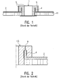
- This steel armor when filling and especially emptying the torpedo ladle against the corrosive attack of the molten pan contents (pig iron and slag), is currently "on site” cast a refractory casting compound, which surrounds the steel armor of the opening from the inside, outside and top, such as described below with reference to FIG. 1.
- Fig. 1 shows schematically a section of the central portion of a torpedo fir, in which a filling opening 1 is provided.
- a portion of the outer steel shell 2 of the torpedo ladle which is formed in the region of the filling opening as a vertically upstanding, annular steel armor 4.
- a Feuerfestmautation FF is schematically indicated.
- the already mentioned refractory casting compound 5 is introduced from above, to protect the steel armor from inside, outside and above when it solidifies.
- the innovation is based on the object, the filling opening of torpedo plugs form so that no annoying cracking occurs, and that the formation of "bears" no advance is made.
- the progress that can be achieved with the help of the innovation results primarily from the fact that only two prefabricated refractory and wear-resistant shaped bricks are needed to ensure the protection of the steel armor.
- prefabricated molded blocks eliminates the introduction of a refractory casting of above and the resulting rough upper surface of the refractory material.
- the prefabricated conglomerates of suitable refractory materials according to the invention have been cast in their preparation so that the surfaces wetted later by the pig iron are formed smooth and free of pores.
- the stones are thermally treated prior to their installation and can thus be installed completely crack-free.
- the smooth surfaces achieved thereby provide no prerequisite for the formation of adherent disturbing "bears".
- the torpedo ladle has an outer steel shell 2 and a multilayer refractory lining facing the ladle interior.
- the circular cross-section of the Torpedopfanneninneren merges in the region of the filling opening in a frusto-conical cross-section, in which area the steel shell 2 merges into a steel tank associated with the filling 4.
- the steel armor 4 is in the form of a truncated cone tapering upwards, so that with respect to the filling opening, the walls of the steel armor are inclined relative to each other.
- a horizontally outwardly projecting ring 6 can be seen, which preferably consists of steel and is preferably welded to the upper end of the steel armor 4.
- each curb 8, 8 ' comprises a base portion 9 and 9', respectively, whose outer peripheral surface bears against the inner surface of the upper end portion of the steel armor 4, and also each an outwardly projecting collar 11, 11 '.
- the curbs 8, 8 ' are dimensioned so that the outer peripheral surfaces of their base portions 9 and 9' are received between the end portions of the steel armor 4, and the undersides of the projecting collar 11 and 11 'on the top of the outwardly projecting ring. 6 support. In this way, the circumference of the annular steel armor 4 is protected from contact with aggressive molten media.
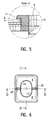
- Fig. 4 shows a partial longitudinal section along line IV-IV in Fig. 6.
- curbs 8 and 8 ' are in contact with the inner wall of the steel armor 4 with their outer surfaces, and that the collar 11 or 11 protruding horizontally outwards in the drawing 'These curbs overlap the steel armor and are supported on a ring 6, which is overlapped by the collar 11 protective.
- the inner surfaces 14 and 14 'of the curbs 8 and 8' define the area of the filling opening available for the average of a molten medium and form a flow opening 13 indicated in FIG.
- Each of the two curbs 8 and 8 ' has, as shown in Fig. 6, a U-shaped configuration with a central web and two lateral legs. If the two curbs are placed directly against each other with their legs or joined together by means of an intermediate intermediate medium, then the arrangement shown in Fig. 6, in which between the legs and the webs of the two U-shaped curbs 8 and 8 'for the passage the molten medium available range of the filling opening, ie the flow opening 13 is formed.
- the two curbs 8 and 8 'in their arrangement of FIG. 6 in the filling opening i. Inserted in the upper end region of the steel armor 4, the two curbs form almost the entire circumference of the filling opening, i. the steel armor 4, overarching protection, which effectively prevents the molten medium during filling of Torpedopfanne, and in particular when emptying the torpedo firing with the filling opening, in particular the upper edge of the steel armor 4 comes into contact.
- the two curbs 8 and 8 ' are preferably identical in design to reduce manufacturing costs and inventory. However, special circumstances may make it necessary to design the two curbs required to protect a filling opening, deviating from one another, which will be the case in particular when the steel armor 4 to be protected has a discontinuous course.
- Fig. 5 shows a detail of Fig. 4 and can be particularly well seen as the collar 11, the steel armor 4 and the outer ring 6 welded thereto protective overlaps.
- the reference numerals 14 and 14 ' designate the walls of the flow-through opening 13 through which the molten medium flows (FIG. 6).
- Reference numerals 20 in FIGS. 3 and 6 are preferably wedge-shaped receiving spaces in the boundary surfaces of adjacent curbs 8 and 8 '. These receiving spaces can be filled with the aid of a refractory material, whereby a locking of the two curbs is achieved.
- the curbs 8 and 8 ' are made of refractory material, as is well known for slurry specific requirements in the use of molten media. Depending on the requirements, the material can be selected so that temperatures up to 1650 ° C are harmless for the curb. Ceramic is suitable for this purpose, eg a dense refractory concrete with about 95% by weight Al 2 O 3 . For other temperatures or other casting material but other refractory materials can be used.
- the two curbs forming the refractory filling opening can be detachably fastened to the steel armor 4 by means of a screw connection 18.
- the curbs are interchangeable, so that when excessive wear or damage replacement can be made.
- the screw is preferably screwed from the outside of the steel armor 4 in the curbs, so that the screws do not come into contact with the molten medium.
- curbs used in the casting of these stones casting direction can be chosen so that the wetted by the use of pig iron surfaces of the stones are formed smooth and free of pores. Since the curbs are treated thermally before installation, they can be installed completely crack-free. The resulting smooth surfaces make it difficult to form "bears".
- the outer edges of the projecting collars 11 and 11 ' which are overflowed by the casting material when pouring out the molten cup contents, may be provided with a pouring and / or drip edge.
- the pouring edge helps to create a well-defined spout while the drip edge provides a defined location for droplet formation from which drops may fall or flow back into the pan.
Landscapes
- Engineering & Computer Science (AREA)
- Mechanical Engineering (AREA)
- Casting Support Devices, Ladles, And Melt Control Thereby (AREA)
- Refinement Of Pig-Iron, Manufacture Of Cast Iron, And Steel Manufacture Other Than In Revolving Furnaces (AREA)
- Carbon Steel Or Casting Steel Manufacturing (AREA)
- Furnace Housings, Linings, Walls, And Ceilings (AREA)
- Elevator Door Apparatuses (AREA)
- Moulds For Moulding Plastics Or The Like (AREA)
Abstract
Description
- Die Neuerung betrifft eine Einfüllöffnung für Torpedopfannen und Randsteine zum Schutz der Einfüllöffnung von Torpedopfannen vor dem korrosiven Angriff schmelzflüssiger Medien, wie Roheisen und Schlacke. Torpedopfannen werden vielerorts für den Transport von flüssigem Roheisens zwischen Hochofen und Stahlwerk benutzt. Diese Gefäße haben ein Fassungsvermögen bis etwa 450 t und verdanken ihren Namen ihrer schlanken, zigarrenförmigen Gestalt.
- Die Torpedopfannen haben zumeist in ihrem Mittelabschnitt eine Einfüllöffnung, durch welche schmelzflüssiges Roheisen in das Innere der Torpedopfanne gegeben wird. Zum Entleeren wird die Torpedopfanne so gekippt, dass der schmelzflüssige Inhalt der Torpedopfanne durch die zuvor zum Einfüllen benutzte Öffnung entleert wird.
- Es versteht sich, dass insbesondere durch das Entleeren der Umfang der Einfüllöffnung stark beansprucht und somit hohem Verschleiß unterworfen ist.
- Nach dem heutigen Stande der Technik umfasst die Einfüllöffnung von Torpedopfannen einen ringförmigen Stahlpanzer, der sich senkrecht zur Oberfläche des Torpedopfannenmittelabschnittes erstreckt. Um diesen Stahlpanzer beim Befüllen und insbesondere Entleeren der Torpedopfanne vor dem korrosiven Angriff des schmelzflüssigen Pfanneninhaltes (Roheisen und Schlacke) zu schützen, wird derzeit "vor Ort" eine feuerfeste Gießmasse vergossen, welche den Stahlpanzer der Öffnung von innen, außen und oben umgibt, wie nachfolgend anhand von Fig. 1 beschrieben.
- Fig. 1 zeigt schematisch einen Ausschnitt aus dem Mittelabschnitt einer Torpedopfanne, in welchem eine Einfüllöffnung 1 vorgesehen ist. Zu erkennen ist ein Teilbereich der äußeren Stahlhülle 2 der Torpedopfanne, welche im Bereich der Einfüllöffnung als senkrecht hochstehender, ringförmiger Stahlpanzer 4 ausgebildet ist. Innerhalb der Stahlhülle 2 ist schematisch eine Feuerfestmauerung FF angedeutet. Mit Hilfe einer Schablone S wird die schon erwähnte feuerfeste Gießmasse 5 von oben eingebracht, um nach ihrem Erstarren den Stahlpanzer von innen, außen und oben schützend zu umgeben.
- Dieser herkömmliche Aufbau der Einzelöffnung einer Torpedopfanne hat sich insofern als nachteilig erwiesen, als
- 1. sich als Folge der auftretenden Wärmespannungen häufig Risse oberhalb des Stahlpanzers der Öffnung zeigen, wobei flüssiges Roheisen durch diese Risse eindringen und den Stahlpanzer unterhalb des Feuerfestmaterials zerstören kann, ohne dass diese Zerstörung frühzeitig erkennbar wird, und
- 2. als Folge des Einbringens der feuerfesten Gießmasse von oben nach dem Erstarren der Gießmasse oben eine raue Oberfläche zurückbleibt. Diese unvorteilhafte Oberflächenbeschaffenheit begünstigt das Anhaften von erkaltendem Roheisen, so dass sich fest anhaftende sogenannte "Bären" bilden. Werden diese Bären mechanisch entfernt, so treten häufig mechanische Schäden an dem Feuerfestmaterial auf, was das Aufbringen einer feuerfesten Reparaturspritzmasse erforderlich macht.
- Die vorstehend erwähnte Bildung von Rissen R sowie einer rauen Oberfläche r.O. sind in Fig. 2 schematisch dargestellt.
- Der Neuerung liegt die Aufgabe zugrunde, die Einfüllöffnung von Torpedopfannen so auszubilden, dass keine störende Rissbildung auftritt, und dass der Ausbildung von "Bären" kein Vorschub geleistet wird.
- Diese Aufgabe wird neuerungsgemäß gelöst durch die Gegenstände der Ansprüche 1 und 4.
- Der mit Hilfe der Neuerung erzielbare Fortschritt ergibt sich in erster Linie daraus, dass lediglich zwei vorgefertigte feuerfeste und verschleißbeständige Formsteine benötigt werden, um den Schutz des Stahlpanzers zu gewährleisten. Durch Verwendung vorgefertigter Formsteine entfällt ein Einbringen einer feuerfesten Gießmasse von oben und die sich daraus ergebende raue obere Oberfläche des Feuerfestmaterials. Die erfindungsgemäßen vorgefertigten Formsteine aus geeigneten Feuerfestmaterialien sind bei ihrer Herstellung so gegossen worden, dass die später vom Roheisen benetzten Flächen glatt und porenfrei ausgebildet sind. Die Formsteine werden vor ihrem Einbau definiert thermisch behandelt und können somit völlig rissfrei eingebaut werden. Die dadurch erzielten glatten Oberflächen bieten keine Voraussetzung für das Ausbilden anhaftender störender "Bären".
- Ferner können durch Vermeidung von Stahlbaureparaturen und durch Verringerung der Spritzreparaturen beträchtliche Kosten eingespart und kann die Verfügbarkeit der Torpedopfannen entsprechend erhöht werden. Kürzere Trocknungszeiten der neu zugestellten Torpedopfannen erhöhen ebenfalls deren Verfügbarkeit.
- Bevorzugte Ausführungsformen der Neuerung sind in den Unteransprüchen angegeben.
- Die Neuerung wird im Folgenden anhand von Zeichnungen näher erläutert. In dieser dienen die bereits erörterten
- Fig. 1 und 2
- der Erläuterung des bekannten Standes der Technik, und die
- Fig. 3 bis 6
- der Erläuterung der Erfindung. Dabei zeigt
- Fig. 3
- einen Querschnitt durch eine Torpedopfanne und ihre Einfüllöffnung,
- Fig. 4
- einen Längsschnitt durch den die Einfüllöffnung aufweisenden Mittelabschnitt der Torpedopfanne,
- Fig. 5
- ein Detail aus Fig. 4, und
- Fig. 6
- eine Aufsicht auf eine von zwei Randsteinen geschützte Einfüllöffnung mit einer mittigen Durchflussöffnung.
- Fig. 3 zeigt einen durch die Einfüllöffnung geführten Querschnitt durch eine Torpedopfanne entlang der Linie III-III in Fig. 6. Es ist zu erkennen, dass die Torpedopfanne eine äußere Stahlhülle 2 und eine dem Pfanneninneren zugewandte mehrschichtige feuerfeste Auskleidung aufweist. Ferner ist zu erkennen, dass im dargestellten Ausführungsbeispiel der kreisförmige Querschnitt des Torpedopfanneninneren im Bereich der Einfüllöffnung in einen kegelstumpfförmigen Querschnitt übergeht, wobei in diesem Bereich die Stahlhülle 2 in einen der Einfüllöffnung zugeordneten Stahlpanzer 4 übergeht. Im dargestellten Ausführungsbeispiel verläuft der Stahlpanzer 4 in Form eines sich nach oben verjüngenden Kegelstumpfes, so dass in Bezug auf die Einfüllöffnung die Wandungen des Stahlpanzers gegeneinander geneigt verlaufen.
- Ferner ist in Fig. 3 am oberen Ende des Stahlpanzers 4 ein horizontal nach außen vorspringender Ring 6 zu erkennen, welcher vorzugsweise aus Stahl besteht und vorzugsweise an das obere Ende des Stahlpanzers 4 angeschweißt ist.
- Innerhalb des oberen Endabschnittes des Stahlpanzers 4 sind zwei den Stahlpanzer schützende, vorgefertigte Randsteine 8 und 8' vorgesehen, und zwar in einer Anordnung zueinander, wie in Fig. 6 dargestellt. Jeder Randstein 8, 8' umfasst einen Basisabschnitt 9 bzw. 9', dessen äußere Umfangsfläche an der Innenoberfläche des oberen Endabschnittes des Stahlpanzers 4 anliegt, und ferner jeweils eine nach außen vorspringenden Kragen 11, 11'. Dabei sind die Randsteine 8, 8' so dimensioniert, dass die äußeren Umfangsflächen ihrer Basisabschnitte 9 und 9' zwischen den Endabschnitten des Stahlpanzers 4 aufgenommen sind, und sich die Unterseiten der vorspringenden Kragen 11 und 11' auf der Oberseite des nach außen vorspringenden Ringes 6 abstützen. Auf diese Weise ist der Umfang des ringförmigen Stahlpanzers 4 vor dem Kontakt mit aggressiven schmelzflüssigen Medien geschützt.
- Fig. 4 zeigt einen Teil-Längsschnitt gemäß Linie IV-IV in Fig. 6. Im dargestellten Ausführungsbeispiel verlaufen die Wandungen des Stahlpanzers 4, gesehen in Längsrichtung der Torpedopfanne, d.h. in Richtung der Linie IV-IV in Fig. 6, nicht einwärts geneigt, sondern senkrecht. Demzufolge verlaufen in Fig. 4 die Außenwand des geschnitten dargestellten Basisabschnittes 9 senkrecht und nicht einwärts geneigt, wie im Querschnitt gemäß Fig. 3.
- Wie aus Fig. 3 ist auch aus Fig. 4 zu ersehen, dass die Randsteine 8 bzw. 8' mit ihren Außenoberflächen in Anlage an der Innenwand des Stahlpanzers 4 sind, und dass die in der Zeichnung horizontal nach außen vorspringenden Kragen 11 bzw. 11' dieser Randsteine die Stahlpanzer übergreifen und sich auf einen Ring 6 abstützen, der von dem Kragen 11 schützend übergriffen wird.
- Die Innenoberflächen 14 und 14' der Randsteine 8 und 8' begrenzen den für den Durchschnitt eines schmelzflüssigen Mediums zur Verfügung stehenden Bereich der Einfüllöffnung und bilden eine in Fig. 6 angegebene Durchflussöffnung 13.
- Jeder der beiden Randsteine 8 und 8' hat, wie in Fig. 6 dargestellt, eine U-förmige Gestalt mit einem Mittelsteg und zwei seitlichen Schenkeln. Werden die beiden Randsteine mit ihren Schenkeln direkt aneinandergelegt oder mit Hilfe eines zwischengefügten Zwischenmediums aneinandergefügt, so ergibt sich die in Fig. 6 gezeigt Anordnung, bei der zwischen den Schenkeln und den Stegen der beiden U-förmigen Randsteine 8 und 8' der für den Durchtritt des schmelzflüssigen Mediums zur Verfügung stehende Bereich der Einfüllöffnung, d.h. die Durchflussöffnung 13 ausgebildet ist.
- Sind die beiden Randsteine 8 und 8' in ihrer Anordnung gemäß Fig. 6 in die Einfüllöffnung, d.h. in den oberen Endbereich des Stahlpanzers 4 eingesetzt, so bilden die beiden Randsteine einen fast den gesamten Umfang der Einfüllöffnung, d.h. des Stahlpanzers 4, übergreifenden Schutz, mit welchem wirksam verhindert wird, dass das schmelzflüssige Medium beim Befüllen der Torpedopfanne, und insbesondere beim Entleeren der Torpedopfanne mit der Einfüllöffnung, insbesondere dem oberen Rand des Stahlpanzers 4, in Berührung gelangt.
- Die beiden Randsteine 8 und 8' sind vorzugsweise identisch gestaltet, um die Fertigungskosten und die Lagerhaltung zu vermindern. Besondere Umstände können es jedoch erforderlich machen, die beiden zum Schutz einer Einfüllöffnung benötigten Randsteine, abweichend voneinander, zu gestalten, was insbesondere dann der Fall sein wird, wenn der zu schützende Stahlpanzer 4 einen unstetigen Verlauf aufweist.
- Fig. 5 zeigt ein Detail aus Fig. 4 und lässt besonders gut erkennen, wie der Kragen 11 den Stahlpanzer 4 und den daran angeschweißten äußeren Ring 6 schützend übergreift. Die Bezugszeichen 14 und 14' bezeichnen die Wandungen der von dem schmelzflüssigen Medium durchströmten Durchflussöffnung 13 (Fig. 6). Mit dem Bezugszeichen 20 sind in den Fig. 3 und 6 vorzugsweise keilförmige Aufnahmeräume in den Grenzflächen benachbarter Randsteine 8 und 8' bezeichnet. Diese Aufnahmeräume können mit Hilfe eines Feuerfestwerkstoffes gefüllt werden, wodurch eine Verriegelung der beiden Randsteine erzielt wird.
- Die Randsteine 8 und 8' bestehen aus feuerfestem Material, wie es für hüttenspezifische Anforderungen bei der Verwendung von schmelzflüssigen Medien allgemein bekannt ist. Je nach Anforderung kann das Material so ausgewählt werden, dass Temperaturen bis zu 1650° C für den Randstein unschädlich sind. Hierfür eignet sich Keramik, z.B. ein dichter Feuerbeton mit etwa 95 Gew.-% Al2O3. Für andere Temperaturen oder anderes Gießmaterial können aber auch andere hitzebeständige Materialien verwendet werden.
- Die beiden die feuerfeste Einfüllöffnung bildenden Randsteine können mit Hilfe einer Schraubverbindung 18 lösbar am Stahlpanzer 4 befestigt sein. Auf diese Weise sind die Randsteine auswechselbar, so dass bei übermäßigem Verschleiß oder Beschädigung ein Auswechseln vorgenommen werden kann. Die Schraubverbindung wird vorzugsweise von der Außenseite des Stahlpanzers 4 in die Randsteine eingeschraubt, so dass die Schrauben nicht mit dem schmelzflüssigen Medium in Berührung gelangen.
- Durch das Vorfertigen der Randsteine kann die beim Gießen dieser Steine benutzte Gießrichtung so gewählt werden, dass die durch den Gebrauch vom Roheisen benetzten Flächen der Formsteine glatt und porenfrei ausgebildet werden. Da die Randsteine vor dem Einbau definiert thermisch behandelt werden, können sie völlig rissfrei eingebaut werden. Die dadurch erzielten glatten Oberflächen erschweren das Ausbilden von "Bären".
- Die beim Ausgießen des schmelzflüssigen Pfanneninhaltes von dem Gießmaterial überströmten Außenkanten der vorspringenden Kragen 11 und 11' können mit einer Gieß- und/oder einer Tropfkante versehen sein. Die Gießkante hilft, einen klar abgegrenzten Ausgussstrahl zu erzeugen, wohingegen die Tropfkante einen definierten Ort für die Tropfenbildung schafft, von welchem Tropfen herunterfallen oder in die Pfanne zurückfließen können.
Claims (5)
- Einfüllöffnung für Torpedopfannen, wobei die Einfüllöffnung einen Stahlpanzer (4) aufweist, dessen oberer Randbereich mittels eines Feuerfestmaterials vor dem Kontakt mit schmelzflüssigen Materialien, wie Metallschmelze und Schlacke, geschützt ist, dadurch gekennzeichnet, dass das Feuerfestmaterial aus zwei vorgefertigten, vorzugsweise identisch gestalteten, im Wesentlichen U-förmigen, Randsteinen (8, 8') besteht, wobei jeder der beiden Randsteine einen Basisabschnitt (9, 9') und einen über den Basisabschnitt nach außen horizontal vorspringenden Kragen (11) aufweist, und dass die beiden Randsteine spiegelbildlich so zueinander angeordnet sind, dass sie allseitig eine Durchflussöffnung (13) umschließen, wobei die Außenoberflächen der Basisabschnitte (9, 9') an den Verlauf der Innenoberfläche des Stahlpanzers (4) angepasst sind, und die Kragen (11, 11') so dimensioniert sind, dass sie den oberen Rand des Stahlpanzers (4) schützend übergreifen.
- Einfüllöffnung nach Anspruch 1, dadurch gekennzeichnet, dass am oberen Rand des Stahlpanzers (4) außen ein horizontal vorspringender Ring (6), vorzugsweise aus Stahl, vorgesehen ist, welcher die Kragen (11, 11') der Randsteine (8, 8') abstützt.
- Einfüllöffnung nach Anspruch 1 oder 2, dadurch gekennzeichnet, dass die beiden Randsteine (8, 8') mit Hilfe einer Schraubverbindung (18) am oberen Endabschnitt des Stahlpanzers (4) befestigt sind.
- Randstein aus Feuerfestmaterial für die Einfüllöffnung von Torpedopfannen, gekennzeichnet durch eine im Wesentlichen U-förmige Gestalt mit einem Basisabschnitt (9, 9') und einem nach außen über den Basisabschnitt vorspringenden Kragen (11, 11'), wobei der Randstein (8, 8') so dimensioniert ist, dass er- mit seinem Basisbereich (9, 9') in einen in der Einfüllöffnung vorgesehenen Stahlpanzer (4) einsetzbar ist, dass- der Kragen den Stahlpanzer (4) schützend übergreift und- mit Hilfe von zwei dieser Randsteine der überwiegende Teil des Umfangs der Einfüllöffnung schützend übergreifbar ist.
- Randstein nach Anspruch 4, dadurch gekennzeichnet, dass der Kragen (11, 11') so dimensioniert ist, dass er auch einen an dem Stahlring (4) angebrachten Außenring (6) schützend übergreift.
Applications Claiming Priority (1)
| Application Number | Priority Date | Filing Date | Title |
|---|---|---|---|
| DE202005019967U DE202005019967U1 (de) | 2005-12-21 | 2005-12-21 | Einfüllöffnung für Torpedopfannen und Randstein zum Einsetzen in die Einfüllöffnung |
Publications (3)
| Publication Number | Publication Date |
|---|---|
| EP1806189A2 true EP1806189A2 (de) | 2007-07-11 |
| EP1806189A3 EP1806189A3 (de) | 2008-08-27 |
| EP1806189B1 EP1806189B1 (de) | 2010-08-11 |
Family
ID=36121133
Family Applications (1)
| Application Number | Title | Priority Date | Filing Date |
|---|---|---|---|
| EP06026320A Not-in-force EP1806189B1 (de) | 2005-12-21 | 2006-12-19 | Einfüllöffnung für Torpedopfannen |
Country Status (3)
| Country | Link |
|---|---|
| EP (1) | EP1806189B1 (de) |
| AT (1) | ATE477072T1 (de) |
| DE (2) | DE202005019967U1 (de) |
Cited By (1)
| Publication number | Priority date | Publication date | Assignee | Title |
|---|---|---|---|---|
| CN102825247A (zh) * | 2012-08-15 | 2012-12-19 | 济钢集团有限公司 | 一种鱼雷型铁水罐罐口 |
Citations (2)
| Publication number | Priority date | Publication date | Assignee | Title |
|---|---|---|---|---|
| US2341054A (en) | 1942-12-24 | 1944-02-08 | Pennsylvania Engineering Works | Free flow hot metal ladle |
| CS226484B1 (cs) | 1982-11-26 | 1984-03-19 | Lankoci Ales | Vylévací hrdlo rotační nádoby, zejména nádoby pojízdného mísiče |
-
2005
- 2005-12-21 DE DE202005019967U patent/DE202005019967U1/de not_active Expired - Lifetime
-
2006
- 2006-12-19 AT AT06026320T patent/ATE477072T1/de active
- 2006-12-19 EP EP06026320A patent/EP1806189B1/de not_active Not-in-force
- 2006-12-19 DE DE502006007628T patent/DE502006007628D1/de active Active
Patent Citations (2)
| Publication number | Priority date | Publication date | Assignee | Title |
|---|---|---|---|---|
| US2341054A (en) | 1942-12-24 | 1944-02-08 | Pennsylvania Engineering Works | Free flow hot metal ladle |
| CS226484B1 (cs) | 1982-11-26 | 1984-03-19 | Lankoci Ales | Vylévací hrdlo rotační nádoby, zejména nádoby pojízdného mísiče |
Cited By (1)
| Publication number | Priority date | Publication date | Assignee | Title |
|---|---|---|---|---|
| CN102825247A (zh) * | 2012-08-15 | 2012-12-19 | 济钢集团有限公司 | 一种鱼雷型铁水罐罐口 |
Also Published As
| Publication number | Publication date |
|---|---|
| EP1806189A3 (de) | 2008-08-27 |
| DE502006007628D1 (de) | 2010-09-23 |
| DE202005019967U1 (de) | 2006-03-16 |
| EP1806189B1 (de) | 2010-08-11 |
| ATE477072T1 (de) | 2010-08-15 |
Similar Documents
| Publication | Publication Date | Title |
|---|---|---|
| DE2627896C2 (de) | Bodenausguß für einen Zwischenbehälter für flüssige Metalle | |
| DE2259553B2 (de) | Zwischenbehälter für Stranggießanlagen | |
| DE3630274A1 (de) | Mit einer innenauskleidung versehener behaelter | |
| DE3240097A1 (de) | Metallurgisches gefaess | |
| DE2715707C2 (de) | Vorrichtung zur Wärmeableitung unter dem Schmelzenauftreffbereich in einem Zwischengefäß | |
| EP0181853B1 (de) | Gasspülstein für metallurgische Öfen und Gefässe | |
| EP0105868A1 (de) | Metallurgischer Ofen oder metallurgisches Gefäss | |
| EP1806189B1 (de) | Einfüllöffnung für Torpedopfannen | |
| DE102010016128B4 (de) | Feuerfeste Auskleidung | |
| DE2924467A1 (de) | Rotationsventil | |
| DE1951349A1 (de) | Ausgussstutzen fuer eine Giesspfanne mit langer Standzeit | |
| EP2380682A2 (de) | Wassergekühlter Deckel für ein Behandlungsgefäß für Metallschmelzen | |
| DE2628455C3 (de) | Formsteine zum Aufbau des Futters eines metallurgischen Gefäßes | |
| DE19513798C2 (de) | Gleitschieberanordnung | |
| EP0653261B1 (de) | Verteilergefäss und Auslaufblock für dieses | |
| DE2830199C2 (de) | Feuerfeste Platte für einen Schieber-Verschluß an Metallschmelze enthaltenden Gefäßen | |
| DE102009036699B4 (de) | Pfannenrandstein | |
| EP0729800B1 (de) | Verfahren zur Wiederherstellung der Feuerfestauskleidung einer Stahlgusspfanne | |
| CH671533A5 (de) | ||
| DE102011089908B4 (de) | Bremsscheibe | |
| AT526023A1 (de) | Stranggießanlage von Stahl | |
| EP0770440B1 (de) | Pfanne zum Aufnehmen von heissem, flüssigem Gussmaterial und für diese Pfanne bestimmter Randstein | |
| DE2633054C2 (de) | Vorrichtung zur Einleitung von Gasen in Flüssigkeiten enthaltende Reaktionsgefäße | |
| DE7500855U (de) | Schieberplatte für Gleitschieberventile von GieBgefäßen | |
| DE8100896U1 (de) | "feuerfester eintauchausguss" |
Legal Events
| Date | Code | Title | Description |
|---|---|---|---|
| PUAI | Public reference made under article 153(3) epc to a published international application that has entered the european phase |
Free format text: ORIGINAL CODE: 0009012 |
|
| AK | Designated contracting states |
Kind code of ref document: A2 Designated state(s): AT BE BG CH CY CZ DE DK EE ES FI FR GB GR HU IE IS IT LI LT LU LV MC NL PL PT RO SE SI SK TR |
|
| AX | Request for extension of the european patent |
Extension state: AL BA HR MK YU |
|
| PUAL | Search report despatched |
Free format text: ORIGINAL CODE: 0009013 |
|
| AK | Designated contracting states |
Kind code of ref document: A3 Designated state(s): AT BE BG CH CY CZ DE DK EE ES FI FR GB GR HU IE IS IT LI LT LU LV MC NL PL PT RO SE SI SK TR |
|
| AX | Request for extension of the european patent |
Extension state: AL BA HR MK RS |
|
| 17P | Request for examination filed |
Effective date: 20090227 |
|
| AKX | Designation fees paid |
Designated state(s): AT BE BG CH CY CZ DE DK EE ES FI FR GB GR HU IE IS IT LI LT LU LV MC NL PL PT RO SE SI SK TR |
|
| GRAP | Despatch of communication of intention to grant a patent |
Free format text: ORIGINAL CODE: EPIDOSNIGR1 |
|
| RTI1 | Title (correction) |
Free format text: FILLING OPENING FOR TORPEDO LADLES |
|
| GRAS | Grant fee paid |
Free format text: ORIGINAL CODE: EPIDOSNIGR3 |
|
| GRAA | (expected) grant |
Free format text: ORIGINAL CODE: 0009210 |
|
| AK | Designated contracting states |
Kind code of ref document: B1 Designated state(s): AT BE BG CH CY CZ DE DK EE ES FI FR GB GR HU IE IS IT LI LT LU LV MC NL PL PT RO SE SI SK TR |
|
| REG | Reference to a national code |
Ref country code: GB Ref legal event code: FG4D Free format text: NOT ENGLISH |
|
| REG | Reference to a national code |
Ref country code: CH Ref legal event code: EP |
|
| REG | Reference to a national code |
Ref country code: IE Ref legal event code: FG4D Free format text: LANGUAGE OF EP DOCUMENT: GERMAN |
|
| REF | Corresponds to: |
Ref document number: 502006007628 Country of ref document: DE Date of ref document: 20100923 Kind code of ref document: P |
|
| REG | Reference to a national code |
Ref country code: NL Ref legal event code: VDEP Effective date: 20100811 |
|
| LTIE | Lt: invalidation of european patent or patent extension |
Effective date: 20100811 |
|
| PG25 | Lapsed in a contracting state [announced via postgrant information from national office to epo] |
Ref country code: LT Free format text: LAPSE BECAUSE OF FAILURE TO SUBMIT A TRANSLATION OF THE DESCRIPTION OR TO PAY THE FEE WITHIN THE PRESCRIBED TIME-LIMIT Effective date: 20100811 Ref country code: FI Free format text: LAPSE BECAUSE OF FAILURE TO SUBMIT A TRANSLATION OF THE DESCRIPTION OR TO PAY THE FEE WITHIN THE PRESCRIBED TIME-LIMIT Effective date: 20100811 Ref country code: NL Free format text: LAPSE BECAUSE OF FAILURE TO SUBMIT A TRANSLATION OF THE DESCRIPTION OR TO PAY THE FEE WITHIN THE PRESCRIBED TIME-LIMIT Effective date: 20100811 |
|
| PG25 | Lapsed in a contracting state [announced via postgrant information from national office to epo] |
Ref country code: SI Free format text: LAPSE BECAUSE OF FAILURE TO SUBMIT A TRANSLATION OF THE DESCRIPTION OR TO PAY THE FEE WITHIN THE PRESCRIBED TIME-LIMIT Effective date: 20100811 Ref country code: CY Free format text: LAPSE BECAUSE OF FAILURE TO SUBMIT A TRANSLATION OF THE DESCRIPTION OR TO PAY THE FEE WITHIN THE PRESCRIBED TIME-LIMIT Effective date: 20100811 Ref country code: BG Free format text: LAPSE BECAUSE OF FAILURE TO SUBMIT A TRANSLATION OF THE DESCRIPTION OR TO PAY THE FEE WITHIN THE PRESCRIBED TIME-LIMIT Effective date: 20101111 Ref country code: PL Free format text: LAPSE BECAUSE OF FAILURE TO SUBMIT A TRANSLATION OF THE DESCRIPTION OR TO PAY THE FEE WITHIN THE PRESCRIBED TIME-LIMIT Effective date: 20100811 Ref country code: PT Free format text: LAPSE BECAUSE OF FAILURE TO SUBMIT A TRANSLATION OF THE DESCRIPTION OR TO PAY THE FEE WITHIN THE PRESCRIBED TIME-LIMIT Effective date: 20101213 Ref country code: IS Free format text: LAPSE BECAUSE OF FAILURE TO SUBMIT A TRANSLATION OF THE DESCRIPTION OR TO PAY THE FEE WITHIN THE PRESCRIBED TIME-LIMIT Effective date: 20101211 |
|
| REG | Reference to a national code |
Ref country code: IE Ref legal event code: FD4D |
|
| PG25 | Lapsed in a contracting state [announced via postgrant information from national office to epo] |
Ref country code: GR Free format text: LAPSE BECAUSE OF FAILURE TO SUBMIT A TRANSLATION OF THE DESCRIPTION OR TO PAY THE FEE WITHIN THE PRESCRIBED TIME-LIMIT Effective date: 20101112 Ref country code: SE Free format text: LAPSE BECAUSE OF FAILURE TO SUBMIT A TRANSLATION OF THE DESCRIPTION OR TO PAY THE FEE WITHIN THE PRESCRIBED TIME-LIMIT Effective date: 20100811 Ref country code: LV Free format text: LAPSE BECAUSE OF FAILURE TO SUBMIT A TRANSLATION OF THE DESCRIPTION OR TO PAY THE FEE WITHIN THE PRESCRIBED TIME-LIMIT Effective date: 20100811 |
|
| PG25 | Lapsed in a contracting state [announced via postgrant information from national office to epo] |
Ref country code: DK Free format text: LAPSE BECAUSE OF FAILURE TO SUBMIT A TRANSLATION OF THE DESCRIPTION OR TO PAY THE FEE WITHIN THE PRESCRIBED TIME-LIMIT Effective date: 20100811 Ref country code: IE Free format text: LAPSE BECAUSE OF FAILURE TO SUBMIT A TRANSLATION OF THE DESCRIPTION OR TO PAY THE FEE WITHIN THE PRESCRIBED TIME-LIMIT Effective date: 20100811 |
|
| PG25 | Lapsed in a contracting state [announced via postgrant information from national office to epo] |
Ref country code: IT Free format text: LAPSE BECAUSE OF FAILURE TO SUBMIT A TRANSLATION OF THE DESCRIPTION OR TO PAY THE FEE WITHIN THE PRESCRIBED TIME-LIMIT Effective date: 20100811 Ref country code: RO Free format text: LAPSE BECAUSE OF FAILURE TO SUBMIT A TRANSLATION OF THE DESCRIPTION OR TO PAY THE FEE WITHIN THE PRESCRIBED TIME-LIMIT Effective date: 20100811 Ref country code: EE Free format text: LAPSE BECAUSE OF FAILURE TO SUBMIT A TRANSLATION OF THE DESCRIPTION OR TO PAY THE FEE WITHIN THE PRESCRIBED TIME-LIMIT Effective date: 20100811 Ref country code: SK Free format text: LAPSE BECAUSE OF FAILURE TO SUBMIT A TRANSLATION OF THE DESCRIPTION OR TO PAY THE FEE WITHIN THE PRESCRIBED TIME-LIMIT Effective date: 20100811 Ref country code: CZ Free format text: LAPSE BECAUSE OF FAILURE TO SUBMIT A TRANSLATION OF THE DESCRIPTION OR TO PAY THE FEE WITHIN THE PRESCRIBED TIME-LIMIT Effective date: 20100811 |
|
| PLBE | No opposition filed within time limit |
Free format text: ORIGINAL CODE: 0009261 |
|
| STAA | Information on the status of an ep patent application or granted ep patent |
Free format text: STATUS: NO OPPOSITION FILED WITHIN TIME LIMIT |
|
| BERE | Be: lapsed |
Owner name: BECK U. KALTHEUNER, FEUERFESTE ERZEUGNISSE G.M.B. Effective date: 20101231 |
|
| PG25 | Lapsed in a contracting state [announced via postgrant information from national office to epo] |
Ref country code: ES Free format text: LAPSE BECAUSE OF FAILURE TO SUBMIT A TRANSLATION OF THE DESCRIPTION OR TO PAY THE FEE WITHIN THE PRESCRIBED TIME-LIMIT Effective date: 20101122 |
|
| 26N | No opposition filed |
Effective date: 20110512 |
|
| PG25 | Lapsed in a contracting state [announced via postgrant information from national office to epo] |
Ref country code: MC Free format text: LAPSE BECAUSE OF NON-PAYMENT OF DUE FEES Effective date: 20101231 |
|
| REG | Reference to a national code |
Ref country code: CH Ref legal event code: PL |
|
| REG | Reference to a national code |
Ref country code: DE Ref legal event code: R097 Ref document number: 502006007628 Country of ref document: DE Effective date: 20110512 |
|
| PG25 | Lapsed in a contracting state [announced via postgrant information from national office to epo] |
Ref country code: BE Free format text: LAPSE BECAUSE OF NON-PAYMENT OF DUE FEES Effective date: 20101231 |
|
| PG25 | Lapsed in a contracting state [announced via postgrant information from national office to epo] |
Ref country code: CH Free format text: LAPSE BECAUSE OF NON-PAYMENT OF DUE FEES Effective date: 20101231 Ref country code: LI Free format text: LAPSE BECAUSE OF NON-PAYMENT OF DUE FEES Effective date: 20101231 |
|
| PG25 | Lapsed in a contracting state [announced via postgrant information from national office to epo] |
Ref country code: HU Free format text: LAPSE BECAUSE OF FAILURE TO SUBMIT A TRANSLATION OF THE DESCRIPTION OR TO PAY THE FEE WITHIN THE PRESCRIBED TIME-LIMIT Effective date: 20110212 Ref country code: LU Free format text: LAPSE BECAUSE OF NON-PAYMENT OF DUE FEES Effective date: 20101219 |
|
| PG25 | Lapsed in a contracting state [announced via postgrant information from national office to epo] |
Ref country code: TR Free format text: LAPSE BECAUSE OF FAILURE TO SUBMIT A TRANSLATION OF THE DESCRIPTION OR TO PAY THE FEE WITHIN THE PRESCRIBED TIME-LIMIT Effective date: 20100811 |
|
| REG | Reference to a national code |
Ref country code: AT Ref legal event code: MM01 Ref document number: 477072 Country of ref document: AT Kind code of ref document: T Effective date: 20111219 |
|
| PG25 | Lapsed in a contracting state [announced via postgrant information from national office to epo] |
Ref country code: AT Free format text: LAPSE BECAUSE OF NON-PAYMENT OF DUE FEES Effective date: 20111219 |
|
| REG | Reference to a national code |
Ref country code: FR Ref legal event code: PLFP Year of fee payment: 10 |
|
| REG | Reference to a national code |
Ref country code: FR Ref legal event code: PLFP Year of fee payment: 11 |
|
| PGFP | Annual fee paid to national office [announced via postgrant information from national office to epo] |
Ref country code: GB Payment date: 20161222 Year of fee payment: 11 |
|
| PGFP | Annual fee paid to national office [announced via postgrant information from national office to epo] |
Ref country code: FR Payment date: 20161222 Year of fee payment: 11 |
|
| PGFP | Annual fee paid to national office [announced via postgrant information from national office to epo] |
Ref country code: DE Payment date: 20161223 Year of fee payment: 11 |
|
| REG | Reference to a national code |
Ref country code: DE Ref legal event code: R119 Ref document number: 502006007628 Country of ref document: DE |
|
| GBPC | Gb: european patent ceased through non-payment of renewal fee |
Effective date: 20171219 |
|
| REG | Reference to a national code |
Ref country code: FR Ref legal event code: ST Effective date: 20180831 |
|
| PG25 | Lapsed in a contracting state [announced via postgrant information from national office to epo] |
Ref country code: FR Free format text: LAPSE BECAUSE OF NON-PAYMENT OF DUE FEES Effective date: 20180102 Ref country code: DE Free format text: LAPSE BECAUSE OF NON-PAYMENT OF DUE FEES Effective date: 20180703 |
|
| PG25 | Lapsed in a contracting state [announced via postgrant information from national office to epo] |
Ref country code: GB Free format text: LAPSE BECAUSE OF NON-PAYMENT OF DUE FEES Effective date: 20171219 |