EP1806227A2 - Couple d'impression et unité d'impression d'une machine pouvant imprimer une largeur de six pages de journal - Google Patents
Couple d'impression et unité d'impression d'une machine pouvant imprimer une largeur de six pages de journal Download PDFInfo
- Publication number
- EP1806227A2 EP1806227A2 EP06125797A EP06125797A EP1806227A2 EP 1806227 A2 EP1806227 A2 EP 1806227A2 EP 06125797 A EP06125797 A EP 06125797A EP 06125797 A EP06125797 A EP 06125797A EP 1806227 A2 EP1806227 A2 EP 1806227A2
- Authority
- EP
- European Patent Office
- Prior art keywords
- printing
- printing unit
- cylinder
- unit according
- roller
- Prior art date
- Legal status (The legal status is an assumption and is not a legal conclusion. Google has not performed a legal analysis and makes no representation as to the accuracy of the status listed.)
- Withdrawn
Links
- 238000007639 printing Methods 0.000 title claims abstract description 127
- 238000007774 anilox coating Methods 0.000 claims description 9
- 230000008020 evaporation Effects 0.000 claims description 2
- 238000001704 evaporation Methods 0.000 claims description 2
- 230000002093 peripheral effect Effects 0.000 claims 1
- 108091006146 Channels Proteins 0.000 description 15
- 239000002184 metal Substances 0.000 description 12
- 238000009826 distribution Methods 0.000 description 8
- 238000003860 storage Methods 0.000 description 7
- 238000007598 dipping method Methods 0.000 description 4
- 230000005284 excitation Effects 0.000 description 2
- 238000007645 offset printing Methods 0.000 description 2
- 238000005086 pumping Methods 0.000 description 2
- 239000007921 spray Substances 0.000 description 2
- YKMMLFOYDTYAGR-UHFFFAOYSA-N 1-phenyl-2-(propan-2-ylamino)pentan-1-one Chemical compound CCCC(NC(C)C)C(=O)C1=CC=CC=C1 YKMMLFOYDTYAGR-UHFFFAOYSA-N 0.000 description 1
- 230000015572 biosynthetic process Effects 0.000 description 1
- 239000004918 carbon fiber reinforced polymer Substances 0.000 description 1
- 239000011248 coating agent Substances 0.000 description 1
- 238000000576 coating method Methods 0.000 description 1
- 238000004040 coloring Methods 0.000 description 1
- 238000006073 displacement reaction Methods 0.000 description 1
- 230000009977 dual effect Effects 0.000 description 1
- 238000004519 manufacturing process Methods 0.000 description 1
- 238000000034 method Methods 0.000 description 1
- 238000000465 moulding Methods 0.000 description 1
- 210000002445 nipple Anatomy 0.000 description 1
- 239000003973 paint Substances 0.000 description 1
- 239000004033 plastic Substances 0.000 description 1
- 238000005096 rolling process Methods 0.000 description 1
- 230000035945 sensitivity Effects 0.000 description 1
- 230000003319 supportive effect Effects 0.000 description 1
- XLYOFNOQVPJJNP-UHFFFAOYSA-N water Substances O XLYOFNOQVPJJNP-UHFFFAOYSA-N 0.000 description 1
Images



Classifications
-
- B—PERFORMING OPERATIONS; TRANSPORTING
- B41—PRINTING; LINING MACHINES; TYPEWRITERS; STAMPS
- B41F—PRINTING MACHINES OR PRESSES
- B41F7/00—Rotary lithographic machines
- B41F7/02—Rotary lithographic machines for offset printing
- B41F7/12—Rotary lithographic machines for offset printing using two cylinders one of which serves two functions, e.g. as a transfer and impression cylinder in perfecting machines
-
- B—PERFORMING OPERATIONS; TRANSPORTING
- B41—PRINTING; LINING MACHINES; TYPEWRITERS; STAMPS
- B41F—PRINTING MACHINES OR PRESSES
- B41F13/00—Common details of rotary presses or machines
- B41F13/004—Electric or hydraulic features of drives
- B41F13/0045—Electric driving devices
-
- B—PERFORMING OPERATIONS; TRANSPORTING
- B41—PRINTING; LINING MACHINES; TYPEWRITERS; STAMPS
- B41F—PRINTING MACHINES OR PRESSES
- B41F13/00—Common details of rotary presses or machines
- B41F13/08—Cylinders
- B41F13/085—Cylinders with means for preventing or damping vibrations or shocks
-
- B—PERFORMING OPERATIONS; TRANSPORTING
- B41—PRINTING; LINING MACHINES; TYPEWRITERS; STAMPS
- B41F—PRINTING MACHINES OR PRESSES
- B41F13/00—Common details of rotary presses or machines
- B41F13/08—Cylinders
- B41F13/22—Means for cooling or heating forme or impression cylinders
-
- B—PERFORMING OPERATIONS; TRANSPORTING
- B41—PRINTING; LINING MACHINES; TYPEWRITERS; STAMPS
- B41F—PRINTING MACHINES OR PRESSES
- B41F13/00—Common details of rotary presses or machines
- B41F13/08—Cylinders
- B41F13/24—Cylinder-tripping devices; Cylinder-impression adjustments
- B41F13/26—Arrangement of cylinder bearings
- B41F13/28—Bearings mounted eccentrically of the cylinder axis
-
- B—PERFORMING OPERATIONS; TRANSPORTING
- B41—PRINTING; LINING MACHINES; TYPEWRITERS; STAMPS
- B41F—PRINTING MACHINES OR PRESSES
- B41F13/00—Common details of rotary presses or machines
- B41F13/08—Cylinders
- B41F13/24—Cylinder-tripping devices; Cylinder-impression adjustments
- B41F13/26—Arrangement of cylinder bearings
- B41F13/30—Bearings mounted on sliding supports
-
- B—PERFORMING OPERATIONS; TRANSPORTING
- B41—PRINTING; LINING MACHINES; TYPEWRITERS; STAMPS
- B41F—PRINTING MACHINES OR PRESSES
- B41F27/00—Devices for attaching printing elements or formes to supports
- B41F27/12—Devices for attaching printing elements or formes to supports for attaching flexible printing formes
-
- B—PERFORMING OPERATIONS; TRANSPORTING
- B41—PRINTING; LINING MACHINES; TYPEWRITERS; STAMPS
- B41F—PRINTING MACHINES OR PRESSES
- B41F31/00—Inking arrangements or devices
-
- B—PERFORMING OPERATIONS; TRANSPORTING
- B41—PRINTING; LINING MACHINES; TYPEWRITERS; STAMPS
- B41F—PRINTING MACHINES OR PRESSES
- B41F31/00—Inking arrangements or devices
- B41F31/002—Heating or cooling of ink or ink rollers
-
- B—PERFORMING OPERATIONS; TRANSPORTING
- B41—PRINTING; LINING MACHINES; TYPEWRITERS; STAMPS
- B41F—PRINTING MACHINES OR PRESSES
- B41F31/00—Inking arrangements or devices
- B41F31/02—Ducts, containers, supply or metering devices
- B41F31/027—Ink rail devices for inking ink rollers
Definitions
- the invention relates to a printing unit and printing units of a six newspaper page wide printing machine, in particular newspaper rotary printing machine, according to the preamble of claim 1 or 26 or 28.
- 2/1, 2/2 and 4/2 systems are inherently rigid for high pressure and offset printing.
- 4/1 and 6/2 systems require special measures. However, the measures taken so far in 4/1 and 6/2 systems are for 6/1 systems "with a single plate set", ie with six printing plates or printing page, especially newspaper page in the axial direction and a printing plate or printing page, especially newspaper page in the circumferential direction, insufficient.
- the flexural rigidity of a 6 individual plates or newspaper pages wide plate cylinder with clamping or mounting channels with single circumference is completely insufficient for vibration-free running at the usual high speeds for z. B. 70,000 to 90,000 newspapers / hour, ie revolutions of the forme cylinder / hour.
- the WO / 002081213 A2 has a printing unit with a four newspaper pages wide forme cylinder simple scope to the subject, the solution described there the circumferentially offset printing plates and possibly the linear arrangement of the four cylinders of a double printing unit on six newspaper pages wide printing units is applicable. In this case, however, it may be advantageous to design the transfer cylinder and / or the forme cylinder with double circumference.
- Particularly advantageous may be the execution of the applicator roll with one or more detachable - and thus changeable - elevators. This can on the one hand reduce costs and, in the case of a coercively driven application roller, can help to avoid the expense of replacing the entire roller.
- the invention has for its object to provide a less susceptible to vibration printing unit and printing units of a six-page wide printing press.
- the invention proposes the clamping of a single slender form cylinder between two at least double-sized, stiff, z.
- B similar rubber cylinders or between a blanket cylinder (transfer cylinder) and a large application roller before.
- Bearer rings at bale ends can, if necessary, be used with strong, clearance-free preloaded bearings. omitted. However, they can also be used for compressive prestressing of the cylinders and precise center distances.
- the achievable with the present invention consist in particular that a significant reduction in vibration can be achieved by the special arrangement and / or expression of the printing cylinder and / or the inking unit. Due to the special arrangement and characteristics of the applicator roller, other, possibly more complex measures can be supported or even eliminated.
- variable web widths and print image widths i.V.m. a continuous cylinder molding channel occupancy of the transfer cylinder, with only two three-page-wide lifts, or even done with only a single six-sideways elevator.
- narrow clamping or fastening channels for receiving the printing plate ends on the forme cylinder and / or vulcanized blanket plates on clamping plates can advantageously be used for long, narrow cylinders.
- narrow attachment channels for example, ⁇ 5 mm, in particular at most 3 mm, in the circumferential direction
- the cylinder bearings can be moved as close as possible to the cylinder bales, i. the cylinder pin receiving bearing, in particular the Lagerauf anyway, may advantageously lie on the frame inner side of the printing unit.
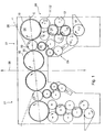
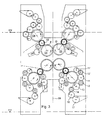
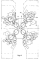
- Fig. 1 to Fig. 7 relate to embodiments of printing units of a web-fed rotary printing press with printing units, which a so-called. 6/1-forme cylinder 02, d. H. a forme cylinder 02 having a circumference corresponding to a print page, in particular a newspaper page (single-circumference form cylinder) and a length corresponding to six print pages, in particular six print images of a newspaper page.
- the forme cylinder 02 then carries, for example, six printing forms, but at least several printing forms with a total of six printed images of a newspaper page next to each other.
- the six printing plates can be arranged aligned in terms of production and handling in a substantially continuous in the axial direction over the entire length of the bale fastening channel. Alternatively, reducing the vibration sensitivity, one pair of adjacent printing plates may be connected to the next pair, e.g. B. 180 ° alternately, offset in the circumferential direction be arranged in correspondingly offset channel sections.
- the forme cylinder 02 acts with a relation to the forme cylinder 02 larger, z. B. double-sized, transfer cylinder 03, also called rubber cylinder 03, on the one hand, and with respect to the forme cylinder 02 larger, z. B. double size, inking roller 04 of an associated inking unit 06 on the other side together.
- "Double big” here means a scope corresponding to two printed pages.
- the Application roller 04 is here at least twice as large, ie it can also be formed three times large.
- the transfer cylinder may be formed triple or even four times large.
- the inking roller 04 has on its periphery either a firmly applied or advantageously releasable compressible and / or elastic layer 15, e.g. a comparable with a blanket of a transfer cylinder rubber layer 15, on.
- the applicator roll 04 may in an advantageous embodiment in the manner of a "second transfer cylinder" or a blanket cylinder with a detachable elevator 15, z. B. a blanket 15 with a pressure blanket 10 of the transfer cylinder 03 comparable structure, eg. B. with a metal blanket 15 may be formed.
- a printing block from a 6/2 blanket cylinder 03 and a 6/2 applicator roller 04 with intervening 6/1 forme cylinder 02 or in other words, two 6/2 blanket cylinders 03; 04 with intervening 6/1 forme cylinder 02.
- the transfer cylinder 03 has on its lateral surface, for example, one or more (eg three) lifts, z. B. blankets 10, in particular multi-layered blankets such as so-called.
- the ends of the respective adjacent printing blankets can each be offset by 180 ° relative to one another.
- the printing blanket 10 formed as a multi-layer printing blanket 10, in particular metal blanket 10, has a dimensionally stable support plate with an elastic layer.
- the folded ends of the same eg without the layer are formed so that for receiving in the transfer cylinder 03 mounting channels with very narrow openings, eg ⁇ 5mm, in particular at most 3 mm, in the circumferential direction can be provided.
- a throughput of the transfer cylinder 03 with only two three-page-wide elevators 10, or even with only a single six-sideways elevator 10, can take place in conjunction with a continuous cylinder mold channel.
- one, two or three detachable lifts 15, e.g. Blankets 15, be provided side by side, the ends of which are held in one or more channels of the applicator roller 04.
- the blankets 15 can then be executed as to the blankets 10, as a "normal” to exciting blanket, or be designed as a dimensionally stable metal blanket.
- transfer cylinder 03, forme cylinder 02 and inking roller 04 are in pressure-on (ie they are paired against each other) preferably in a common plane E.
- the same division, d. H. are e.g. the same size, z. B. both with twice the size of the forme cylinder 02, executed.
- the large applicator roll 04 also have one or more channels (either only as an interruption in the firmly applied layer or as a channel for attaching detachable lifts 15). This or these should correspond in number and spacing in the circumferential direction of those or those of the transfer cylinder channels and at the same time to those arranged on the forme cylinder 02 expiring, so that the discharge takes place simultaneously.
- Two such printing units 01 against each other form a rubber / rubber printing unit for simultaneous perfecting (1/1-pressure). It is provided in a particularly advantageous embodiment, that the axes of rotation of the applicator rollers 04, the forming and transfer cylinders 02; 03; 04 of both co-operating printing units 01 are in pressure-An in a common plane E (Fig. 1 and 2).
- the rubber / rubber printing units can be stacked several times, z. B. four times, and z. B. to 4/4 printing tower or more are stacked (Fig. 2).
- the rubber / rubber printing units can also be arranged angled to each other, so that the plane E of the printing unit 01 with a connecting plane D of the pressure point forming transfer cylinder 03 forms an angle> 0. Two angular rubber / rubber printing units can then crash together to form a H-printing unit with two double pressure points.
- transfer cylinder 03, forme cylinder 02 and inking unit 06 may be formed against a central printing cylinder 07 as a four-color satellite printing unit.
- a second satellite printing unit with opposite direction of rotation is mounted in a manner known per se.
- the - in printing units with at least two printing blocks (printing units 01) - inside transfer cylinder 03 transfer the print images of 6/1 cylinders 02 in the process Blanket- / Blanketdruck on the interposed guided paper web 08.
- the outer application rollers 04 and blanket cylinder 04 have a dual function. They replace the usual application rollers - so they serve themselves as ever a large application roller 04, z. B. with a lift 15 (eg, a coating 15 or a blanket 15, in particular metal blanket 15) with the excellent surface quality of an offset blanket 10 and a metal blanket 10.
- the latter can be found between two identical 6/2 rubber cylinders 03; 04 or a 6/2 rubber cylinder 03 and a 6/2 applicator roller 04 clamped and can not bend anymore.
- the applicator rollers 04 or external blanket cylinder 04 part can be usual or new inking 06 and inked.
- the applicator roll 04 may be part of a film, a pump or a lift inking unit.
- the inking unit 06 is exemplarily designed as einwirkiges roller inking unit 06 (also "long inking unit") and has (at least) the color on the printing plate 05 applying large inking roller 04, which the color on (at least) a forme-shaped iridescent transfer cylinder 11 (eg with a hard surface), a color or transfer roller 12 (eg with a soft surface), (at least) an iridescent printing cylinder 13 remote from the printing device, a further inking or transfer roller 14 (eg. B. soft surface), a film roll 16 and a Ductor or dipping roller 17 from a color box 18 receives.
- a forme-shaped iridescent transfer cylinder 11 eg with a hard surface
- a color or transfer roller 12 eg with a soft surface
- an iridescent printing cylinder 13 remote from the printing device eg. B. soft surface
- a further inking or transfer roller 14 eg. B. soft surface
- Dipping and film roller 16; 17 can also by another Farbzu Georgia- or. dosing system (eg pumping system in the pumping inking unit, or lifting system in the lifting inking unit).
- dosing system eg pumping system in the pumping inking unit, or lifting system in the lifting inking unit.
- two additional distribution cylinders 11 'and 13' can be provided in parallel in the ink path to the former for equalization.
- a further transfer roller 12' can also be provided (see FIG. 5).
- the further transfer roller 12 ' should then as indicated by the double arrow, z. B. about the axis of rotation of the adjacent transfer roller 12, be pivoted to make the way for the applicator roll 04 for the purpose of on / off free.
- dampening units 09 which supply the form cylinder 02 with pre-moistening or moistening with water with a dampening roller 21.
- a dampening roller 21 for wet offset usual dampening units 09 are provided which supply the form cylinder 02 with pre-moistening or moistening with water with a dampening roller 21.
- a dampening roller 21 for wet offset usual dampening units 09 are provided which supply the form cylinder 02 with pre-moistening or moistening with water with a dampening roller 21.
- a dampening unit 09 in particular spray dampening unit 09, are shown.
- Waterless offset eliminates dampening.
- Fig. 4 shows (for example also applicable by way of example to Fig. 1, 2 or 3) the formation of the inking unit 06 as a short or anilox inking unit.
- This is -. B. in zonenloser coloring - each outer blanket cylinder 04 or each applicator roller 04 of an anilox (anilox) anilox roller 22 with doctoring chamber 23 colored. If this is done with dampening or dampening 09 wet offset, the evaporation surface should be at least as large as in conventional wet offset inking, so that the color is not prematurely emulsified in the circuit anilox roller 22, chamber blade 23, ink fountain and paint pump in an advantageous embodiment.
- This is here z. B. accomplished by a system of several additional, employed on the applicator roller 04 rollers 24.
- Fig. 5 an embodiment of the printing unit 01 and the rubber-rubber printing unit is shown, in contrast to Fig. 1 in the inking unit 06, the applicator roller 04 with two On / Ab suiten color or transfer roller 12 cooperates, which in turn from a distribution cylinder 11, another color or transfer roller 12, a second distribution cylinder 13, two ink or transfer rollers 14, a film roller 16 and a ductor or dipping roller 17 of a Color box 18 gets the color.
- circles is within the adjustable rollers 12; 14 indicated an advantageous embodiment, these adjustable rollers are mounted in pneumatically actuated and lockable roller locks.
- the transfer cylinder 03, the forme cylinder 02 and the applicator roller 04 each in storage units 27; 28; 29 with linear travel and corresponding linear guides, in particular along the plane E or a maximum deviation of the direction of adjustment of the plane E of z. B. 20 °, advantageously less than 10 °, in particular about 0 °, are stored.
- the angle between the direction of adjustment and a connecting plane of the cylinder / roller to be set is advantageously less than 20 °, advantageously less than 10 °, in particular approximately 0 °, to the cylinder / roller closest to the pressure point.
- Fig. 6 shows a printing tower with four stacked rubber-rubber printing units.
- FIG. 7 an embodiment of the printing unit 01 and the rubber-rubber printing unit is shown, wherein the inking unit 06 is formed in contrast to the inking unit of FIG. 1 stretched with a substantially horizontal color flow. This arrangement reduces the height.
- each printing unit 01 at each printing unit 01 a Aufplatt Anlagen 31, z.
- a semi-automatic or fully automatic disc changer be provided at each printing unit 01 .
- An arrangement of a bearing for the cylinder 02 is advantageous; 03 and / or the large applicator roller 04, wherein a Lagerauftician for the journal of the cylinder 02; 03 in one of the escape of the side frame inward, i. to the cylinders 02; 03 and the roller 04 is provided out outstanding area.
- the pin receiving radial bearing either in a side frame arranged storage unit (eccentric bearing unit or as above linear bearing unit) to be stored, wherein the radial bearing is at least partially on the frame inside in the direction cylinder / roller outstanding, or a bearing having the radial bearing unit can total be releasably attached to the frame inside.
- the pair of forming and transfer cylinder at least one of other printing units and the inking unit 06 mechanically independent drive motor, and the applicator roll 04 one of the cylinders 02; 03 mechanically independent drive motor.
- the bales may be formed in a development as a hollow cylinder.
- This hollow cylinder may be formed as a metal tube or as a plastic, in particular CFRP tube and the front side metallic hubs and / or pins.
Landscapes
- Engineering & Computer Science (AREA)
- Mechanical Engineering (AREA)
- Rotary Presses (AREA)
Applications Claiming Priority (2)
| Application Number | Priority Date | Filing Date | Title |
|---|---|---|---|
| DE200620000229 DE202006000229U1 (de) | 2006-01-09 | 2006-01-09 | Druckwerk mit einem Formzylinder, Übertragungszylinder und Farbauftragswalze |
| DE102006012468 | 2006-03-18 |
Publications (2)
| Publication Number | Publication Date |
|---|---|
| EP1806227A2 true EP1806227A2 (fr) | 2007-07-11 |
| EP1806227A3 EP1806227A3 (fr) | 2011-01-19 |
Family
ID=37846060
Family Applications (1)
| Application Number | Title | Priority Date | Filing Date |
|---|---|---|---|
| EP06125797A Withdrawn EP1806227A3 (fr) | 2006-01-09 | 2006-12-11 | Couple d'impression et unité d'impression d'une machine pouvant imprimer une largeur de six pages de journal |
Country Status (1)
| Country | Link |
|---|---|
| EP (1) | EP1806227A3 (fr) |
Citations (2)
| Publication number | Priority date | Publication date | Assignee | Title |
|---|---|---|---|---|
| EP1161345B1 (fr) | 1999-03-12 | 2002-08-14 | Koenig & Bauer Aktiengesellschaft | Groupe d'impression d'une presse d'imprimerie rotative |
| WO2002081213A2 (fr) | 2001-04-09 | 2002-10-17 | Koenig & Bauer Aktiengesellschaft | Groupe d'impression d'une machine d'imprimerie, procede pour abaisser et relever un cylindre, et procede de realisation d'un produit imprime |
Family Cites Families (4)
| Publication number | Priority date | Publication date | Assignee | Title |
|---|---|---|---|---|
| BE557069A (fr) * | ||||
| DE3705194A1 (de) * | 1987-02-19 | 1988-09-01 | Frankenthal Ag Albert | Farbwerk |
| US5341733A (en) * | 1990-03-03 | 1994-08-30 | Albert Frankenthal Aktiengesellschaft | Short inking apparatus for a rotary press |
| US5207158A (en) * | 1991-02-19 | 1993-05-04 | Rockwell International | Long lived, variable-delivery ink metering method, system and roller for keyless lithography |
-
2006
- 2006-12-11 EP EP06125797A patent/EP1806227A3/fr not_active Withdrawn
Patent Citations (2)
| Publication number | Priority date | Publication date | Assignee | Title |
|---|---|---|---|---|
| EP1161345B1 (fr) | 1999-03-12 | 2002-08-14 | Koenig & Bauer Aktiengesellschaft | Groupe d'impression d'une presse d'imprimerie rotative |
| WO2002081213A2 (fr) | 2001-04-09 | 2002-10-17 | Koenig & Bauer Aktiengesellschaft | Groupe d'impression d'une machine d'imprimerie, procede pour abaisser et relever un cylindre, et procede de realisation d'un produit imprime |
Also Published As
| Publication number | Publication date |
|---|---|
| EP1806227A3 (fr) | 2011-01-19 |
Similar Documents
| Publication | Publication Date | Title |
|---|---|---|
| EP1574332B1 (fr) | Unité d'impression d'une presse d'impression | |
| EP0549936B1 (fr) | Cylindre de transfert avec manchon échangeable, supporté entre deux parois latérales d'un élément d'impression | |
| DD283788A5 (de) | Rollendruckmaschine fuer den schoen- und widerdruck, insbesondere von banknoten | |
| DE10016409A1 (de) | Zylinder einer Rotationsdruckmaschine | |
| DE102009002103B4 (de) | Druckmaschine und ein Verfahren zum Bedrucken eines bahnförmigen Bedruckstoffs | |
| EP1740380B1 (fr) | Unite d'impression d'une imprimeuse rotative a bobines polychrome et procede d'utilisation | |
| EP1806227A2 (fr) | Couple d'impression et unité d'impression d'une machine pouvant imprimer une largeur de six pages de journal | |
| WO2006133938A2 (fr) | Cylindre de transfert pour une largeur d'impression d'au moins cinq pages | |
| EP1712354B1 (fr) | Unité d'impression d'une presse rotative | |
| EP1434693B1 (fr) | Presse rotative a bobines | |
| EP1365916B1 (fr) | Unite d'impression | |
| EP1733879B1 (fr) | Machine d'impression rotative à bobines et procédé de fabrication de plaques d'impression pour une telle machine | |
| DE102010001594A1 (de) | Farbwerke und Druckeinheit einer Druckmaschine |
Legal Events
| Date | Code | Title | Description |
|---|---|---|---|
| PUAI | Public reference made under article 153(3) epc to a published international application that has entered the european phase |
Free format text: ORIGINAL CODE: 0009012 |
|
| AK | Designated contracting states |
Kind code of ref document: A2 Designated state(s): AT BE BG CH CY CZ DE DK EE ES FI FR GB GR HU IE IS IT LI LT LU LV MC NL PL PT RO SE SI SK TR |
|
| AX | Request for extension of the european patent |
Extension state: AL BA HR MK YU |
|
| PUAL | Search report despatched |
Free format text: ORIGINAL CODE: 0009013 |
|
| AK | Designated contracting states |
Kind code of ref document: A3 Designated state(s): AT BE BG CH CY CZ DE DK EE ES FI FR GB GR HU IE IS IT LI LT LU LV MC NL PL PT RO SE SI SK TR |
|
| AX | Request for extension of the european patent |
Extension state: AL BA HR MK RS |
|
| 17P | Request for examination filed |
Effective date: 20101223 |
|
| STAA | Information on the status of an ep patent application or granted ep patent |
Free format text: STATUS: THE APPLICATION HAS BEEN WITHDRAWN |
|
| 18W | Application withdrawn |
Effective date: 20110812 |
|
| AKX | Designation fees paid |
Designated state(s): AT BE BG CH CY CZ DE DK EE ES FI FR GB GR HU IE IS IT LI LT LU LV MC NL PL PT RO SE SI SK TR |