EP1806307A2 - Wechselvorrichtung - Google Patents
Wechselvorrichtung Download PDFInfo
- Publication number
- EP1806307A2 EP1806307A2 EP06123729A EP06123729A EP1806307A2 EP 1806307 A2 EP1806307 A2 EP 1806307A2 EP 06123729 A EP06123729 A EP 06123729A EP 06123729 A EP06123729 A EP 06123729A EP 1806307 A2 EP1806307 A2 EP 1806307A2
- Authority
- EP
- European Patent Office
- Prior art keywords
- machine
- roller
- band
- extending
- guide
- Prior art date
- Legal status (The legal status is an assumption and is not a legal conclusion. Google has not performed a legal analysis and makes no representation as to the accuracy of the status listed.)
- Granted
Links
- 238000000034 method Methods 0.000 claims abstract description 13
- 238000003780 insertion Methods 0.000 description 3
- 230000037431 insertion Effects 0.000 description 3
- 125000006850 spacer group Chemical group 0.000 description 2
- 238000004804 winding Methods 0.000 description 2
- 230000001771 impaired effect Effects 0.000 description 1
Images


Classifications
-
- B—PERFORMING OPERATIONS; TRANSPORTING
- B65—CONVEYING; PACKING; STORING; HANDLING THIN OR FILAMENTARY MATERIAL
- B65H—HANDLING THIN OR FILAMENTARY MATERIAL, e.g. SHEETS, WEBS, CABLES
- B65H20/00—Advancing webs
- B65H20/06—Advancing webs by friction band
-
- D—TEXTILES; PAPER
- D21—PAPER-MAKING; PRODUCTION OF CELLULOSE
- D21F—PAPER-MAKING MACHINES; METHODS OF PRODUCING PAPER THEREON
- D21F7/00—Other details of machines for making continuous webs of paper
- D21F7/001—Wire-changing arrangements
-
- B—PERFORMING OPERATIONS; TRANSPORTING
- B65—CONVEYING; PACKING; STORING; HANDLING THIN OR FILAMENTARY MATERIAL
- B65H—HANDLING THIN OR FILAMENTARY MATERIAL, e.g. SHEETS, WEBS, CABLES
- B65H2601/00—Problem to be solved or advantage achieved
- B65H2601/30—Facilitating or easing
- B65H2601/32—Facilitating or easing entities relating to handling machine
- B65H2601/324—Removability or inter-changeability of machine parts, e.g. for maintenance
Definitions
- the invention relates to a method and its use for changing a final and seamless strip of a machine for producing and / or finishing a paper, cardboard, tissue or another fibrous web in which the band is guided around at least one roller, which the ends is held in support parts of the machine chair.
- the support parts of the rollers are held by cantilevers.
- the cantilever beams extend across the entire width of the machine and on the drive side of the machine beyond, where there is a fixation on the building structure.
- the object of the invention is therefore to simplify the band change while sparing the band.
- this object is achieved in that on one side of the machine frame one end of an axially extending to the roller and extending over the width of the belt guide carrier is connected to the support member of the roller, the guide carrier has an axially extending to the roller, outer track, the in the machine over an inner, along the roller extending running track continues, wherein there is a carriage for receiving and guiding the tape on the outer rail, which drives the tape after the removal of intermediate pieces of the machine frame into the machine.
- the band By creating the outer track, the band can be prepared unrequited in its entire width outside the machine on the band change. Also, the retraction of the tape by means of the carriage in the region of the inner track designed much easier.
- the roller can be held on the guide support, so that no Cantilever- or cross member is required for the Supporteile this roller.
- the outer end of the guide carrier should be attached to a crane.
- the tape should be brought after fixing on the carriage over axially extending to the roller drapery in a shape corresponding approximately to the course in the machine.
- the drapery tubes can be fastened with advantage on the guide support.
- the release of the intermediate pieces can be done relatively easily via the lifting of the guide support after loosening corresponding connections in the machine frame.
- the guide carrier can be lifted with advantage over the crane or via a lifting element supported on the foundation.
- the guide carrier should preferably be connected to the guide part of the machine with the support part.
- Particularly non-gatherable are tapes whose surface is harder than that of press felts.
- the use of the method is also advantageous in cases in which the strip is guided through at least one press nip formed by the roll and a counter roll for dewatering the fibrous web.
- the counter-roller should be held at the ends in support parts, which are interconnected via a cross member, wherein the cross member is guided on the, the guide carrier opposite side of the machine frame out of the machine and fixed there to the building.
- This Cantileverung keeps the counter roll with the free support part after loosening the intermediate pieces in their position, thus ensuring the appropriate space for the insertion of the tape. Since this is limited only to the counter-roller, the effort remains relatively low.
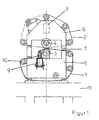
- the press assembly has a press nip through which the fibrous web is fed together with an upper water-absorbing dewatering belt 2 and a smooth, impermeable belt 1.
- the press nip is formed by a lower roll 3 and an upper counter roll 4. These rollers 3,4 are supported by the machine frame, which is supported on the foundation 11.
- the machine chair On the driver's side, the machine chair is formed by separate support parts 5, 6 for supporting the rollers 3, 4. These support members 5,6 are releasably connected to each other, with removable spacers 7 between them.
- the upper support part 6 of the leader side of the counter roll 4 is connected via an axially extending to the roller 3 cross member 8 with the opposite machine frame.
- the cross member 8 is guided on the opposite drive side of the machine and connected to the foundation 11.
- the bands are 1.2 guided over guide rollers 10.
- the endless circulating transfer belt 1 is not only seamless but also smooth and thus not gatherable, this is performed here with a special changing device in the machine.
- the old tape to be changed 1 can be easily separated and removed from the machine.
- a guide carrier 14 running axially to the roller 3 is frictionally connected to the support part 5 of the roller 3 on the driver's side of the machine chair.
- This guide carrier 14 has an outer, axially to the roller 3 running rail 12 for guiding a carriage 9th
- This carriage 9 carries the new tape 1, which is fixed on a winding tube on the unwinding of the carriage 9.
- the band 1 can be brought about axially extending to the roller 3 Drapierrohre in a shape corresponding approximately to the course in the machine.
- the drapery tubes can be easily attached to the guide support 14.
- the band 1 need not be gathered, which in particular protects the smooth surface of the band 1.
- the carriage 9 consists here of a sub-carriage at each end of the belt first
- the carriage 9 After assembly of the belt 1 in the machine, the carriage 9 can be moved out of the machine and removed together with the guide support 14.
Landscapes
- Replacement Of Web Rolls (AREA)
- Unwinding Webs (AREA)
- Paper (AREA)
- Character Spaces And Line Spaces In Printers (AREA)
Abstract
Description
- Die Erfindung betrifft ein Verfahren sowie dessen Anwendung zum Wechseln eines end- und nahtlosen Bandes einer Maschine zur Herstellung und/oder Veredlung einer Papier-, Karton-, Tissue- oder einer anderen Faserstoffbahn in der das Band um wenigstens eine Walze geführt ist, welche an den Enden in Supportteilen der Maschinenstuhlung gehalten wird.
- Während Bänder mit einer Verbindungsnaht in der Maschine zusammengefügt werden können, gestaltet sich dies bei nahtlosen Bändern insbesondere bei sehr breiten Maschinen sehr aufwendig.
- Hierzu werden die Supportteile der Walzen über Cantileverträger gehalten. Die Cantileverträger verlaufen quer über die gesamte Breite der Maschine und auf der Triebseite der Maschine darüber hinaus, wobei dort eine Fixierung an der Gebäudestruktur stattfindet.
- Diese Cantileverträger ermöglichen über die Entfernung von Zwischenstücken der Maschinenstuhlung auf der Führerseite das Einziehen des neuen Bandes, welches in geraffter Form für das Einziehen in die Maschine vorbereitet wird.
- Dies ist nicht nur sehr aufwendig, sondern belastet auch die Bänder.
- Die Aufgabe der Erfindung ist es daher, den Bandwechsel bei Schonung des Bandes zu vereinfachen.
- Erfindungsgemäß wurde die Aufgabe dadurch gelöst, dass an einer Seite der Maschinenstuhlung ein Ende eines axial zur Walze verlaufenden und sich über die Breite des Bandes erstreckenden Führungsträgers mit dem Supportteil der Walze verbunden wird, der Führungsträger eine axial zur Walze verlaufende, äußere Laufschiene besitzt, die sich in der Maschine über eine innere, sich entlang der Walze erstreckende Laufschiene fortsetzt, wobei sich auf der äußeren Laufschiene ein Laufwagen zur Aufnahme und Führung des Bandes befindet, welcher das Band nach der Entfernung von Zwischenstücken der Maschinenstuhlung in die Maschine fährt.
- Durch die Schaffung der äußeren Laufschiene kann das Band ungerafft in seiner ganzen Breite außerhalb der Maschine auf den Bandwechsel vorbereitet werden. Auch das Einfahren des Bandes mit Hilfe des Laufwagens in den Bereich der inneren Laufschiene gestaltet sich wesentlich einfacher.
- Außerdem kann die Walze über den Führungsträger gehalten werden, so dass für die Supporteile dieser Walze kein Cantilever- bzw. Querträger erforderlich ist.
- Dies vermindert nicht nur den Aufwand, sondern auch die Belastung der Gebäudestruktur.
- Zur Fixierung sollte hierzu das äußere Ende des Führungsträgers an einem Kran befestigt werden.
- Um das Einführen des Bandes zu vereinfachen und zu beschleunigen, sollte das Band nach der Fixierung am Laufwagen über axial zur Walze verlaufende Drapierrohre in eine etwa dem Verlauf in der Maschine entsprechende Form gebracht werden.
- Dabei können die Drapierrohre mit Vorteil am Führungsträger befestigt werden.
- Um das Band in die Maschine einfahren zu können, müssen erst entsprechende Freiräume in der Maschinenstuhlung, vorzugsweise über das Entfernen von Zwischenstücken geschaffen werden.
- Das Lösen der Zwischenstücke kann nach dem Lösen entsprechender Verbindungen in der Maschinenstuhlung relativ einfach über das Anheben des Führungsträgers erfolgen.
- Der Führungsträgers kann dabei mit Vorteil über den Kran oder über ein sich auf dem Fundament abstützendes Hubelement angehoben werden.
- Wegen der Raumverhältnisse sollte der Führungsträger vorzugsweise auf der Führerseite der Maschine mit dem Supportteil verbunden sein.
- Besonders vorteilhaft ist die Anwendung des Verfahrens nach einem der vorhergehenden Merkmale beim Wechsel eines nicht raffbaren Bandes und/oder eines Bandes mit einer glatten Oberfläche.
- Nicht raffbar sind insbesondere Bänder, deren Oberfläche härter als die von Pressfilzen ist.
- Bei glatten Bändern, insbesondere impermeablen Transferbändern kann durch die Raffung die Oberfläche bleibend stark beeinträchtigt werden.
- Von Vorteil ist die Anwendung des Verfahrens auch in Fällen, in denen das Band durch wenigstens einen, von der Walze und einer Gegenwalze gebildeten Pressspalt zur Entwässerung der Faserstoffbahn geführt wird.
- Dabei sollte die Gegenwalze an den Enden in Supportteilen gehalten werden, welche über einen Querträger miteinander verbunden sind, wobei der Querträger auf der, dem Führungsträger gegenüberliegenden Seite der Maschinenstuhlung aus der Maschine geführt und dort am Gebäude fixiert ist.
- Diese Cantileverung hält die Gegenwalze mit dem freien Supportteil nach dem Lösen der Zwischenstücke in ihre Lage und gewährleistet so die entsprechenden Freiräume für das Einführen des Bandes.
Da dies nur auf die Gegenwalze beschränkt ist, bleibt der Aufwand relativ gering. - Nachfolgend soll die Erfindung an einem Ausführungsbeispiel näher erläutert werden. In der beigefügten Zeichnung zeigt:
- Figur 1:
- eine schematische Seitenansicht einer Pressanordnung;
- Figur 2:
- eine Längsansicht der Pressanordnung vor dem Bandwechsel;
- Figur 3:
- nach dem Entfernen der Zischenstücke 7 und
- Figur 4:
- nach dem Einführen des Bandes 1.
- Die Pressanordnung besitzt einen Pressspalt, durch den die Faserstoffbahn gemeinsam mit einem oberen wasseraufnehmenden Entwässerungsband 2 und einem glatten, impermeablen Band 1 geführt wird.
- Der Pressspalt wird dabei von einer unteren Walze 3 und einer oberen Gegenwalze 4 gebildet. Diese Walzen 3,4 werden von der Maschinenstuhlung getragen, welche sich auf dem Fundament 11 abstützt.
- Auf der Führerseite wird die Maschinenstuhlung von separaten Supportteilen 5,6 zur Lagerung der Walzen 3,4 gebildet. Diese Supportteile 5,6 sind lösbar miteinander verbunden, wobei sich zwischen diesen entfernbare Zwischenstücke 7 befinden.
- Das obere Supportteil 6 der Führerseite der Gegenwalze 4 ist über einen axial zur Walze 3 verlaufenden Querträger 8 mit der gegenüberliegenden Maschinenstuhlung verbunden. Der Querträger 8 wird auf der gegenüberliegenden Triebseite aus der Maschine geführt und mit dem Fundament 11 verbunden.
- Außerhalb des Pressspaltes werden die Bänder 1,2 über Leitwalzen 10 geführt.
- Da das endlos umlaufende Transferband 1 nicht nur nahtlos sondern auch glatt und damit nicht raffbar ist, wird dieses hier mit einer speziellen Wechselvorrichtung in die Maschine geführt.
- Zuvor kann das alte zu wechselnde Band 1 einfach aufgetrennt und aus der Maschine entfernt werden.
- Zur Vorbereitung wird gemäß den Figuren 1 und 2 auf der Führerseite der Maschinenstuhlung ein Ende eines axial zur Walze 3 verlaufenden Führungsträgers 14 mit dem Supportteil 5 der Walze 3 kraftschlüssig verbunden. Dieser Führungsträger 14 besitzt eine äußere, axial zur Walze 3 verlaufende Laufschiene 12 zur Führung eines Laufwagens 9.
- Dieser Laufwagen 9 trägt das neue Band 1, welches auf einem Wickelrohr an der Abwickelvorrichtung des Laufwagens 9 fixiert ist.
- Anschließend kann das Band 1 über axial zur Walze 3 verlaufende Drapierrohre in eine etwa dem Verlauf in der Maschine entsprechende Form gebracht werden. Die Drapierrohre können einfach am Führungsträger 14 befestigt werden.
- Da sich der Führungsträger 14 über die gesamte Breite des Bandes 1 erstreckt, muss das Band 1 nicht gerafft werden, was insbesondere die glatte Oberfläche des Bandes 1 schont.
- Der Laufwagen 9 besteht hier aus je einem Teilwagen an jedem Ende des Bandes 1.
- Über einen Kran kann im Anschluss das freie Ende des Führungsträgers 14 angehoben werden, was die Entnahme der Zwischenstücke 7 erlaubt. Dabei wird, wie Figur 3 zeigt, das obere Supportteil 6 der Gegenwalze 4 von dem Querträger 8 im wesentlichen in seiner Lage gehalten.
- Somit reduziert sich die Belastung der Gebäudestruktur lediglich auf die Cantileverung der oberen Gegenwalze 4.
- Durch die Entnahme der Zwischenstücke 7 sind die Freiräume zum Einführen des Bandes 1 in die Maschine geschaffen.
- Um dies zu erleichtern, befindet sich innerhalb der Maschine eine axial zur Walze 3 verlaufende innere Laufschiene 13, welche sich an die äußere Laufschiene 12 anschließt.
- Auf diese Weise kann der Laufwagen 9 mit dem Band 1 entsprechend Figur 4 einfach in die Maschine gefahren werden. Das restliche, aufgewickelte Band 1 auf dem Wickelrohr wird mit der Abwickelvorrichtung kontrolliert abgewickelt.
- Nach der Montage des Bandes 1 in der Maschine kann der Laufwagen 9 wieder aus der Maschine gefahren und gemeinsam mit dem Führungsträger 14 entfernt werden.
Claims (9)
- Verfahren zum Wechseln eines end- und nahtlosen Bandes (1) einer Maschine zur Herstellung und/oder Veredlung einer Papier-, Karton-, Tissue- oder einer anderen Faserstoffbahn in der das Band (1) um wenigstens eine Walze (3) geführt ist, welche an den Enden in Supportteilen (5) der Maschinenstuhlung gehalten wird, dadurch gekennzeichnet, dass
an einer Seite der Maschinenstuhlung ein Ende eines axial zur Walze (3) verlaufenden und sich über die Breite des Bandes (1) erstreckenden Führungsträgers (14) mit dem Supportteil (5) der Walze (3) verbunden wird, der Führungsträger (14) eine axial zur Walze (3) verlaufende, äußere Laufschiene (12) besitzt, die sich in der Maschine über eine innere, sich entlang der Walze (3) erstreckende Laufschiene (13) fortsetzt, wobei sich auf der äußeren Laufschiene (12) ein Laufwagen (9) zur Aufnahme und Führung des Bandes (1) befindet, welcher das Band (1) nach der Entfernung von Zwischenstücken (7) der Maschinenstuhlung in die Maschine fährt. - Verfahren nach Anspruch 1, dadurch gekennzeichnet, dass
das Band (1) nach der Fixierung am Laufwagen (9) über axial zur Walze (3) verlaufende Drapierrohre in eine etwa dem Verlauf in der Maschine entsprechende Form gebracht wird. - Verfahren nach Anspruch 2, dadurch gekennzeichnet, dass
die Drapierrohre an dem Führungsträger (14) befestigt werden. - Verfahren nach einem der vorhergehenden Ansprüche, dadurch gekennzeichnet, dass
der Führungsträger (14) zum Lösen der Zwischenstücke (7) angehoben wird. - Verfahren nach einem der vorhergehenden Ansprüche, dadurch gekennzeichnet, dass
der Führungsträger (14) auf der Führerseite der Maschine mit dem Supportteil (5) verbunden wird. - Anwendung des Verfahrens nach einem der vorhergehenden Ansprüche, dadurch gekennzeichnet, dass
das Band (1) nicht raffbar ist. - Anwendung des Verfahrens nach einem der vorhergehenden Ansprüche, dadurch gekennzeichnet, dass
das Band (1) eine glatte Oberfläche besitzt. - Anwendung des Verfahrens nach einem der vorhergehenden Ansprüche, dadurch gekennzeichnet, dass
das Band (1) durch wenigstens einen, von der Walze (3) und einer Gegenwalze (4) gebildeten Pressspalt geführt ist. - Anwendung des Verfahrens nach Anspruch 8, dadurch gekennzeichnet, dass die Gegenwalze (4) an den Enden in Supportteilen (6) gehalten wird, welche über einen Querträger (8) miteinander verbunden sind, wobei der Querträger (8) auf der, dem Führungsträger (14) gegenüberliegenden Seite der Maschinenstuhlung aus der Maschine geführt und dort fixiert ist.
Applications Claiming Priority (1)
| Application Number | Priority Date | Filing Date | Title |
|---|---|---|---|
| DE102006001050A DE102006001050A1 (de) | 2006-01-07 | 2006-01-07 | Wechselvorrichtung |
Publications (3)
| Publication Number | Publication Date |
|---|---|
| EP1806307A2 true EP1806307A2 (de) | 2007-07-11 |
| EP1806307A3 EP1806307A3 (de) | 2009-07-22 |
| EP1806307B1 EP1806307B1 (de) | 2011-08-17 |
Family
ID=37907159
Family Applications (1)
| Application Number | Title | Priority Date | Filing Date |
|---|---|---|---|
| EP06123729A Not-in-force EP1806307B1 (de) | 2006-01-07 | 2006-11-09 | Wechselvorrichtung |
Country Status (3)
| Country | Link |
|---|---|
| EP (1) | EP1806307B1 (de) |
| AT (1) | ATE520822T1 (de) |
| DE (1) | DE102006001050A1 (de) |
Cited By (3)
| Publication number | Priority date | Publication date | Assignee | Title |
|---|---|---|---|---|
| CN102852026A (zh) * | 2012-09-21 | 2013-01-02 | 金红叶纸业集团有限公司 | 纸机回头辊毛毯安装方法及装置 |
| CN108884636A (zh) * | 2016-06-24 | 2018-11-23 | 福伊特专利有限公司 | 用于更换造纸机的绷网的设备和方法 |
| CN118127848A (zh) * | 2024-03-20 | 2024-06-04 | 无锡裕力机械有限公司 | 一种适用于悬臂式机架的支撑抽取装置 |
Families Citing this family (5)
| Publication number | Priority date | Publication date | Assignee | Title |
|---|---|---|---|---|
| DE102015211422B3 (de) * | 2015-06-22 | 2016-09-29 | Voith Patent Gmbh | Vorrichtung und Verfahren zum Einziehen einer Bespannung in eine Papiermaschine |
| DE102018112172A1 (de) | 2018-05-22 | 2019-11-28 | Voith Patent Gmbh | Verfahren und Vorrichtung zum Wechseln einer Bespannung in einer Papiermaschine |
| DE102019120924A1 (de) * | 2019-08-02 | 2020-11-05 | Voith Patent Gmbh | Maschine und Verfahren zum Wechseln einer Bespannung in einer Papiermaschine |
| AT526229B1 (de) * | 2023-05-05 | 2024-01-15 | Andritz Ag Maschf | Maschine und verfahren zur herstellung einer faserstoffbahn |
| DE102024121625A1 (de) * | 2024-07-30 | 2025-08-21 | Voith Patent Gmbh | Siebpartie einer Maschine zur Herstellung einer Faserstoffbahn und Verfahren zum Einziehen eines Siebes |
Family Cites Families (1)
| Publication number | Priority date | Publication date | Assignee | Title |
|---|---|---|---|---|
| FI991171A0 (fi) * | 1999-05-24 | 1999-05-24 | Valmet Corp | Menetelmä siirtohihnan vaihtamiseksi paperi- tai kartonkikoneessa |
-
2006
- 2006-01-07 DE DE102006001050A patent/DE102006001050A1/de not_active Withdrawn
- 2006-11-09 EP EP06123729A patent/EP1806307B1/de not_active Not-in-force
- 2006-11-09 AT AT06123729T patent/ATE520822T1/de active
Non-Patent Citations (1)
| Title |
|---|
| None |
Cited By (5)
| Publication number | Priority date | Publication date | Assignee | Title |
|---|---|---|---|---|
| CN102852026A (zh) * | 2012-09-21 | 2013-01-02 | 金红叶纸业集团有限公司 | 纸机回头辊毛毯安装方法及装置 |
| CN102852026B (zh) * | 2012-09-21 | 2015-02-11 | 金红叶纸业集团有限公司 | 纸机回头辊毛毯安装方法及装置 |
| CN108884636A (zh) * | 2016-06-24 | 2018-11-23 | 福伊特专利有限公司 | 用于更换造纸机的绷网的设备和方法 |
| CN108884636B (zh) * | 2016-06-24 | 2020-04-07 | 福伊特专利有限公司 | 用于更换造纸机的绷网的设备和方法 |
| CN118127848A (zh) * | 2024-03-20 | 2024-06-04 | 无锡裕力机械有限公司 | 一种适用于悬臂式机架的支撑抽取装置 |
Also Published As
| Publication number | Publication date |
|---|---|
| EP1806307B1 (de) | 2011-08-17 |
| ATE520822T1 (de) | 2011-09-15 |
| DE102006001050A1 (de) | 2007-07-12 |
| EP1806307A3 (de) | 2009-07-22 |
Similar Documents
| Publication | Publication Date | Title |
|---|---|---|
| DE69512061T3 (de) | Vorrichtung und verfahren zum automatischen wechseln von rollen für bahnförmige materialien | |
| AT505818B1 (de) | Verfahren und anordnung bei einer abrollvorrichtung für eine faserbahn | |
| AT398561B (de) | Wickelmaschine zum gleichzeitigen achslosen aufwickeln der streifen einer längsgeteilten bahn auf wenigstens zwei wickelrollen | |
| DE4401804A1 (de) | Verfahren zum Aufwickeln einer laufenden Bahn sowie Wickelmaschine zum Durchführen des Verfahrens | |
| EP1806307B1 (de) | Wechselvorrichtung | |
| DE19616322B4 (de) | Vertikale Klebepresse | |
| DE3422170C2 (de) | ||
| DE19816510A1 (de) | Bahneinzugsvorrichtung für Rotationsdruckmaschinen | |
| DE3916740C2 (de) | Textilmaschine mit verstellbarer Glättwalzenanordnung | |
| EP1870515B1 (de) | Maschinenstuhlung | |
| EP1798172A2 (de) | Vorrichtung und Verfahren zum Abwickeln einer Materialbahn | |
| DE3418048A1 (de) | Rollengeruest mit rollenwechseleinrichtung fuer folien- oder bandmaterial-rollen | |
| DE112007000421T5 (de) | Verfahren in Verbindung mit einem Längsschneider-Aufwickler | |
| DE102009046584A1 (de) | Bahnzusammenfügungsanordnung für einen Rollenschneider einer Faserbahn und Verfahren zum Zusammenfügen einer alten Bahn mit einer neuen Bahn in einem Rollenschneider | |
| DE3115835C2 (de) | Klebewalze in einer Abwickelanlage | |
| DE60118964T2 (de) | Vorrichtung und verfahren zum wickeln von bahnen | |
| AT410326B (de) | Verfahren und vorrichtung zum wechseln eines rundfilzes | |
| EP3686341B1 (de) | Walzenwechsel | |
| DE4415316A1 (de) | Rollenwickelmaschine | |
| DE60109323T2 (de) | Vorrichtung und verfahren zum wickeln von bahnen | |
| EP2113479B1 (de) | Verfahren zum Überführen einer laufenden Materialbahn sowie Wickelmaschine zur Durchführung des Verfahrens | |
| DE102006000324A1 (de) | Anordnung und Verfahren zum Wechseln eines endlosen Bandes oder dergleichen in einer Papier- oder Kartonmaschine oder Nachbehandlungsmaschine | |
| DE102004046062A1 (de) | Verfahren und Vorrichtung zum Austauschen eines alten Bandes gegen ein neues Band in einer Maschine, insbesondere zum Wechsel eines Filzes in einer Papiermaschine | |
| EP1557386B1 (de) | Verfahren und Vorrichtung zum Aufwickeln einer Papierbahn | |
| AT503731B1 (de) | Verfahren am aufroller einer faserbahnmaschine |
Legal Events
| Date | Code | Title | Description |
|---|---|---|---|
| PUAI | Public reference made under article 153(3) epc to a published international application that has entered the european phase |
Free format text: ORIGINAL CODE: 0009012 |
|
| AK | Designated contracting states |
Kind code of ref document: A2 Designated state(s): AT BE BG CH CY CZ DE DK EE ES FI FR GB GR HU IE IS IT LI LT LU LV MC NL PL PT RO SE SI SK TR |
|
| AX | Request for extension of the european patent |
Extension state: AL BA HR MK YU |
|
| PUAL | Search report despatched |
Free format text: ORIGINAL CODE: 0009013 |
|
| AK | Designated contracting states |
Kind code of ref document: A3 Designated state(s): AT BE BG CH CY CZ DE DK EE ES FI FR GB GR HU IE IS IT LI LT LU LV MC NL PL PT RO SE SI SK TR |
|
| AX | Request for extension of the european patent |
Extension state: AL BA HR MK RS |
|
| RIC1 | Information provided on ipc code assigned before grant |
Ipc: B65H 19/12 20060101ALI20090612BHEP Ipc: D21F 7/00 20060101AFI20090612BHEP |
|
| 17P | Request for examination filed |
Effective date: 20100122 |
|
| 17Q | First examination report despatched |
Effective date: 20100215 |
|
| AKX | Designation fees paid |
Designated state(s): AT BE BG CH CY CZ DE DK EE ES FI FR GB GR HU IE IS IT LI LT LU LV MC NL PL PT RO SE SI SK TR |
|
| GRAP | Despatch of communication of intention to grant a patent |
Free format text: ORIGINAL CODE: EPIDOSNIGR1 |
|
| RAP1 | Party data changed (applicant data changed or rights of an application transferred) |
Owner name: VOITH PATENT GMBH |
|
| GRAS | Grant fee paid |
Free format text: ORIGINAL CODE: EPIDOSNIGR3 |
|
| GRAA | (expected) grant |
Free format text: ORIGINAL CODE: 0009210 |
|
| AK | Designated contracting states |
Kind code of ref document: B1 Designated state(s): AT BE BG CH CY CZ DE DK EE ES FI FR GB GR HU IE IS IT LI LT LU LV MC NL PL PT RO SE SI SK TR |
|
| REG | Reference to a national code |
Ref country code: GB Ref legal event code: FG4D Free format text: NOT ENGLISH |
|
| REG | Reference to a national code |
Ref country code: CH Ref legal event code: EP |
|
| REG | Reference to a national code |
Ref country code: IE Ref legal event code: FG4D Free format text: LANGUAGE OF EP DOCUMENT: GERMAN |
|
| REG | Reference to a national code |
Ref country code: DE Ref legal event code: R096 Ref document number: 502006010026 Country of ref document: DE Effective date: 20111117 |
|
| REG | Reference to a national code |
Ref country code: NL Ref legal event code: VDEP Effective date: 20110817 |
|
| LTIE | Lt: invalidation of european patent or patent extension |
Effective date: 20110817 |
|
| PG25 | Lapsed in a contracting state [announced via postgrant information from national office to epo] |
Ref country code: LT Free format text: LAPSE BECAUSE OF FAILURE TO SUBMIT A TRANSLATION OF THE DESCRIPTION OR TO PAY THE FEE WITHIN THE PRESCRIBED TIME-LIMIT Effective date: 20110817 Ref country code: NL Free format text: LAPSE BECAUSE OF FAILURE TO SUBMIT A TRANSLATION OF THE DESCRIPTION OR TO PAY THE FEE WITHIN THE PRESCRIBED TIME-LIMIT Effective date: 20110817 Ref country code: PT Free format text: LAPSE BECAUSE OF FAILURE TO SUBMIT A TRANSLATION OF THE DESCRIPTION OR TO PAY THE FEE WITHIN THE PRESCRIBED TIME-LIMIT Effective date: 20111219 Ref country code: IS Free format text: LAPSE BECAUSE OF FAILURE TO SUBMIT A TRANSLATION OF THE DESCRIPTION OR TO PAY THE FEE WITHIN THE PRESCRIBED TIME-LIMIT Effective date: 20111217 Ref country code: SE Free format text: LAPSE BECAUSE OF FAILURE TO SUBMIT A TRANSLATION OF THE DESCRIPTION OR TO PAY THE FEE WITHIN THE PRESCRIBED TIME-LIMIT Effective date: 20110817 |
|
| PG25 | Lapsed in a contracting state [announced via postgrant information from national office to epo] |
Ref country code: SI Free format text: LAPSE BECAUSE OF FAILURE TO SUBMIT A TRANSLATION OF THE DESCRIPTION OR TO PAY THE FEE WITHIN THE PRESCRIBED TIME-LIMIT Effective date: 20110817 Ref country code: PL Free format text: LAPSE BECAUSE OF FAILURE TO SUBMIT A TRANSLATION OF THE DESCRIPTION OR TO PAY THE FEE WITHIN THE PRESCRIBED TIME-LIMIT Effective date: 20110817 Ref country code: CY Free format text: LAPSE BECAUSE OF FAILURE TO SUBMIT A TRANSLATION OF THE DESCRIPTION OR TO PAY THE FEE WITHIN THE PRESCRIBED TIME-LIMIT Effective date: 20110817 Ref country code: GR Free format text: LAPSE BECAUSE OF FAILURE TO SUBMIT A TRANSLATION OF THE DESCRIPTION OR TO PAY THE FEE WITHIN THE PRESCRIBED TIME-LIMIT Effective date: 20111118 Ref country code: LV Free format text: LAPSE BECAUSE OF FAILURE TO SUBMIT A TRANSLATION OF THE DESCRIPTION OR TO PAY THE FEE WITHIN THE PRESCRIBED TIME-LIMIT Effective date: 20110817 |
|
| REG | Reference to a national code |
Ref country code: IE Ref legal event code: FD4D |
|
| PG25 | Lapsed in a contracting state [announced via postgrant information from national office to epo] |
Ref country code: IE Free format text: LAPSE BECAUSE OF FAILURE TO SUBMIT A TRANSLATION OF THE DESCRIPTION OR TO PAY THE FEE WITHIN THE PRESCRIBED TIME-LIMIT Effective date: 20110817 Ref country code: CZ Free format text: LAPSE BECAUSE OF FAILURE TO SUBMIT A TRANSLATION OF THE DESCRIPTION OR TO PAY THE FEE WITHIN THE PRESCRIBED TIME-LIMIT Effective date: 20110817 Ref country code: SK Free format text: LAPSE BECAUSE OF FAILURE TO SUBMIT A TRANSLATION OF THE DESCRIPTION OR TO PAY THE FEE WITHIN THE PRESCRIBED TIME-LIMIT Effective date: 20110817 |
|
| BERE | Be: lapsed |
Owner name: VOITH PATENT G.M.B.H. Effective date: 20111130 |
|
| PG25 | Lapsed in a contracting state [announced via postgrant information from national office to epo] |
Ref country code: EE Free format text: LAPSE BECAUSE OF FAILURE TO SUBMIT A TRANSLATION OF THE DESCRIPTION OR TO PAY THE FEE WITHIN THE PRESCRIBED TIME-LIMIT Effective date: 20110817 Ref country code: IT Free format text: LAPSE BECAUSE OF FAILURE TO SUBMIT A TRANSLATION OF THE DESCRIPTION OR TO PAY THE FEE WITHIN THE PRESCRIBED TIME-LIMIT Effective date: 20110817 Ref country code: RO Free format text: LAPSE BECAUSE OF FAILURE TO SUBMIT A TRANSLATION OF THE DESCRIPTION OR TO PAY THE FEE WITHIN THE PRESCRIBED TIME-LIMIT Effective date: 20110817 |
|
| PLBE | No opposition filed within time limit |
Free format text: ORIGINAL CODE: 0009261 |
|
| STAA | Information on the status of an ep patent application or granted ep patent |
Free format text: STATUS: NO OPPOSITION FILED WITHIN TIME LIMIT |
|
| PG25 | Lapsed in a contracting state [announced via postgrant information from national office to epo] |
Ref country code: DK Free format text: LAPSE BECAUSE OF FAILURE TO SUBMIT A TRANSLATION OF THE DESCRIPTION OR TO PAY THE FEE WITHIN THE PRESCRIBED TIME-LIMIT Effective date: 20110817 Ref country code: MC Free format text: LAPSE BECAUSE OF NON-PAYMENT OF DUE FEES Effective date: 20111130 |
|
| REG | Reference to a national code |
Ref country code: CH Ref legal event code: PL |
|
| 26N | No opposition filed |
Effective date: 20120521 |
|
| GBPC | Gb: european patent ceased through non-payment of renewal fee |
Effective date: 20111117 |
|
| PG25 | Lapsed in a contracting state [announced via postgrant information from national office to epo] |
Ref country code: LI Free format text: LAPSE BECAUSE OF NON-PAYMENT OF DUE FEES Effective date: 20111130 Ref country code: CH Free format text: LAPSE BECAUSE OF NON-PAYMENT OF DUE FEES Effective date: 20111130 |
|
| REG | Reference to a national code |
Ref country code: FR Ref legal event code: ST Effective date: 20120731 |
|
| PG25 | Lapsed in a contracting state [announced via postgrant information from national office to epo] |
Ref country code: BE Free format text: LAPSE BECAUSE OF NON-PAYMENT OF DUE FEES Effective date: 20111130 |
|
| REG | Reference to a national code |
Ref country code: DE Ref legal event code: R097 Ref document number: 502006010026 Country of ref document: DE Effective date: 20120521 |
|
| PG25 | Lapsed in a contracting state [announced via postgrant information from national office to epo] |
Ref country code: GB Free format text: LAPSE BECAUSE OF NON-PAYMENT OF DUE FEES Effective date: 20111117 |
|
| PG25 | Lapsed in a contracting state [announced via postgrant information from national office to epo] |
Ref country code: FR Free format text: LAPSE BECAUSE OF NON-PAYMENT OF DUE FEES Effective date: 20111130 |
|
| PGFP | Annual fee paid to national office [announced via postgrant information from national office to epo] |
Ref country code: DE Payment date: 20121121 Year of fee payment: 7 Ref country code: FI Payment date: 20121113 Year of fee payment: 7 |
|
| PGFP | Annual fee paid to national office [announced via postgrant information from national office to epo] |
Ref country code: AT Payment date: 20121113 Year of fee payment: 7 |
|
| PG25 | Lapsed in a contracting state [announced via postgrant information from national office to epo] |
Ref country code: ES Free format text: LAPSE BECAUSE OF FAILURE TO SUBMIT A TRANSLATION OF THE DESCRIPTION OR TO PAY THE FEE WITHIN THE PRESCRIBED TIME-LIMIT Effective date: 20111128 |
|
| PG25 | Lapsed in a contracting state [announced via postgrant information from national office to epo] |
Ref country code: LU Free format text: LAPSE BECAUSE OF NON-PAYMENT OF DUE FEES Effective date: 20111109 |
|
| PG25 | Lapsed in a contracting state [announced via postgrant information from national office to epo] |
Ref country code: BG Free format text: LAPSE BECAUSE OF FAILURE TO SUBMIT A TRANSLATION OF THE DESCRIPTION OR TO PAY THE FEE WITHIN THE PRESCRIBED TIME-LIMIT Effective date: 20111117 |
|
| PG25 | Lapsed in a contracting state [announced via postgrant information from national office to epo] |
Ref country code: TR Free format text: LAPSE BECAUSE OF FAILURE TO SUBMIT A TRANSLATION OF THE DESCRIPTION OR TO PAY THE FEE WITHIN THE PRESCRIBED TIME-LIMIT Effective date: 20110817 |
|
| PG25 | Lapsed in a contracting state [announced via postgrant information from national office to epo] |
Ref country code: HU Free format text: LAPSE BECAUSE OF FAILURE TO SUBMIT A TRANSLATION OF THE DESCRIPTION OR TO PAY THE FEE WITHIN THE PRESCRIBED TIME-LIMIT Effective date: 20110817 |
|
| REG | Reference to a national code |
Ref country code: AT Ref legal event code: MM01 Ref document number: 520822 Country of ref document: AT Kind code of ref document: T Effective date: 20131109 |
|
| PG25 | Lapsed in a contracting state [announced via postgrant information from national office to epo] |
Ref country code: FI Free format text: LAPSE BECAUSE OF NON-PAYMENT OF DUE FEES Effective date: 20131109 Ref country code: AT Free format text: LAPSE BECAUSE OF NON-PAYMENT OF DUE FEES Effective date: 20131109 Ref country code: DE Free format text: LAPSE BECAUSE OF NON-PAYMENT OF DUE FEES Effective date: 20140603 |
|
| REG | Reference to a national code |
Ref country code: DE Ref legal event code: R119 Ref document number: 502006010026 Country of ref document: DE Effective date: 20140603 |