EP1806529A2 - Système de montage pour dispositif électronique de visualisation à écran plat - Google Patents
Système de montage pour dispositif électronique de visualisation à écran plat Download PDFInfo
- Publication number
- EP1806529A2 EP1806529A2 EP07290002A EP07290002A EP1806529A2 EP 1806529 A2 EP1806529 A2 EP 1806529A2 EP 07290002 A EP07290002 A EP 07290002A EP 07290002 A EP07290002 A EP 07290002A EP 1806529 A2 EP1806529 A2 EP 1806529A2
- Authority
- EP
- European Patent Office
- Prior art keywords
- bearing
- flat panel
- electronic display
- panel electronic
- discontinuous
- Prior art date
- Legal status (The legal status is an assumption and is not a legal conclusion. Google has not performed a legal analysis and makes no representation as to the accuracy of the status listed.)
- Withdrawn
Links
Images


Classifications
-
- G—PHYSICS
- G06—COMPUTING OR CALCULATING; COUNTING
- G06F—ELECTRIC DIGITAL DATA PROCESSING
- G06F1/00—Details not covered by groups G06F3/00 - G06F13/00 and G06F21/00
- G06F1/16—Constructional details or arrangements
- G06F1/1601—Constructional details related to the housing of computer displays, e.g. of CRT monitors, of flat displays
-
- F—MECHANICAL ENGINEERING; LIGHTING; HEATING; WEAPONS; BLASTING
- F16—ENGINEERING ELEMENTS AND UNITS; GENERAL MEASURES FOR PRODUCING AND MAINTAINING EFFECTIVE FUNCTIONING OF MACHINES OR INSTALLATIONS; THERMAL INSULATION IN GENERAL
- F16M—FRAMES, CASINGS OR BEDS OF ENGINES, MACHINES OR APPARATUS, NOT SPECIFIC TO ENGINES, MACHINES OR APPARATUS PROVIDED FOR ELSEWHERE; STANDS; SUPPORTS
- F16M11/00—Stands or trestles as supports for apparatus or articles placed thereon ; Stands for scientific apparatus such as gravitational force meters
- F16M11/02—Heads
- F16M11/04—Means for attachment of apparatus; Means allowing adjustment of the apparatus relatively to the stand
- F16M11/06—Means for attachment of apparatus; Means allowing adjustment of the apparatus relatively to the stand allowing pivoting
- F16M11/10—Means for attachment of apparatus; Means allowing adjustment of the apparatus relatively to the stand allowing pivoting around a horizontal axis
- F16M11/105—Means for attachment of apparatus; Means allowing adjustment of the apparatus relatively to the stand allowing pivoting around a horizontal axis the horizontal axis being the roll axis, e.g. for creating a landscape-portrait rotation
-
- F—MECHANICAL ENGINEERING; LIGHTING; HEATING; WEAPONS; BLASTING
- F16—ENGINEERING ELEMENTS AND UNITS; GENERAL MEASURES FOR PRODUCING AND MAINTAINING EFFECTIVE FUNCTIONING OF MACHINES OR INSTALLATIONS; THERMAL INSULATION IN GENERAL
- F16M—FRAMES, CASINGS OR BEDS OF ENGINES, MACHINES OR APPARATUS, NOT SPECIFIC TO ENGINES, MACHINES OR APPARATUS PROVIDED FOR ELSEWHERE; STANDS; SUPPORTS
- F16M11/00—Stands or trestles as supports for apparatus or articles placed thereon ; Stands for scientific apparatus such as gravitational force meters
- F16M11/20—Undercarriages with or without wheels
- F16M11/2007—Undercarriages with or without wheels comprising means allowing pivoting adjustment
- F16M11/2014—Undercarriages with or without wheels comprising means allowing pivoting adjustment around a vertical axis
-
- F—MECHANICAL ENGINEERING; LIGHTING; HEATING; WEAPONS; BLASTING
- F16—ENGINEERING ELEMENTS AND UNITS; GENERAL MEASURES FOR PRODUCING AND MAINTAINING EFFECTIVE FUNCTIONING OF MACHINES OR INSTALLATIONS; THERMAL INSULATION IN GENERAL
- F16M—FRAMES, CASINGS OR BEDS OF ENGINES, MACHINES OR APPARATUS, NOT SPECIFIC TO ENGINES, MACHINES OR APPARATUS PROVIDED FOR ELSEWHERE; STANDS; SUPPORTS
- F16M13/00—Other supports for positioning apparatus or articles; Means for steadying hand-held apparatus or articles
- F16M13/02—Other supports for positioning apparatus or articles; Means for steadying hand-held apparatus or articles for supporting on, or attaching to, an object, e.g. tree, gate, window-frame, cycle
-
- F—MECHANICAL ENGINEERING; LIGHTING; HEATING; WEAPONS; BLASTING
- F16—ENGINEERING ELEMENTS AND UNITS; GENERAL MEASURES FOR PRODUCING AND MAINTAINING EFFECTIVE FUNCTIONING OF MACHINES OR INSTALLATIONS; THERMAL INSULATION IN GENERAL
- F16M—FRAMES, CASINGS OR BEDS OF ENGINES, MACHINES OR APPARATUS, NOT SPECIFIC TO ENGINES, MACHINES OR APPARATUS PROVIDED FOR ELSEWHERE; STANDS; SUPPORTS
- F16M2200/00—Details of stands or supports
- F16M2200/06—Arms
- F16M2200/068—Arms being part of the undercarriage
Definitions
- the present invention is directed to mounts for electronic displays and more specifically to devices for mounting flat panel electronic displays such as plasma and LCD screens on a fixed structure.
- Flat panel displays have become an increasingly popular substitute for projection devices and CRTs.
- the flat panel display is typically mounted on a structure, such as a wall.
- Flat panel displays, especially LCD's, are typically most clearly viewable from a position directly in front of the display.
- the display image is often too dark or not visible at all if viewed from a significant angle.
- the angle of a flat panel display can be adjusted for optimum viewing.
- Various prior art positioning devices have been used, such as friction based hinges, mechanical linkages with springs or other biasing devices, and various mechanical latches.
- Traditional friction based devices and mechanical latches typically require that the flat panel display be held at the correct angle while the device is adjusted to maintain the position on its own. This may require the operator to lift and hold a substantial portion of the weight of the flat panel display. In some instances, the operator must also overcome the resistance of the positioning device.
- hinge and pivot joints used in some prior devices typically enable positioning of the display about only one axis per joint.
- the degree of display position adjustability of such devices is limited by the number of joints that can be economically and practically provided.
- U.S. Patent No. 6,419,196 (Sweere et al. ) discloses a multi-jointed, pivoted support arm to support and position a flat panel display that uses a nitrogen gas spring counterbalance mechanism.
- the mount is geometrically configured so that the center of pivoting motion of the display is positioned proximate the center of gravity of the display.
- This configuration enables the display and mount to be essentially self-balancing so that minimal operator effort is needed to position the display.
- it may be advantageous to provide the ability to selectively adjust the amount of friction in the mount so as to enable the mount to resist accidental repositioning of the display through contact or to "lock" the display in a desired position.
- a drawback of previous friction adjustment mechanisms is that they tend to require significant effort to adjust. Another drawback is that the friction adjustment tends to loosen over time due to the weight of the display.
- the present invention includes a mounting system for a flat panel display that substantially meets the aforementioned needs of the industry.
- a display interface having a hollow, frusto-spherical cup portion is attached to the rear surface of a flat panel electronic display.
- the frusto-spherical cup is clamped between a split outer bearing that engages the outer surface of the cup and an inner bearing disc that engages the inner surface of the cup.
- a friction adjustment screw is provided in a body portion which carries the outer bearing portion, and to which the inner bearing disc is also secured.
- Tightening of the friction adjustment screw causes the outer bearing portion to be forced outward from the body portion against the frusto-spherical cup, clamping it more tightly against the inner bearing disc and thereby providing increased frictional resistance to sliding movement of the frusto-conical cup and display attached thereto relative to the guide structure.
- a knob may be coupled with the friction adjustment screw to enable easy fingertip adjustment of friction. Loosening of the screw likewise causes reduced frictional resistance so that the display can be adjusted as desired for best viewing.
- the frusto-spherical cup may be formed with a radius of curvature having a center disposed proximate the center of gravity of the flat panel display so as to enable positioning of the flat panel display with minimal effort.
- the present invention includes a flat panel electronic display mount including a display mount assembly having a discontinuous bearing, the bearing being expandable radially responsive to an increased frictional biasing force, the biasing force being applied axially to the discontinuous bearing, the radial expandability assisting in maintaining a desired amount of frictional engagement afforded by the discontinuous bearing.
- a flat panel electronic display mount according to an embodiment of the present invention may further include a display mount assembly having a bearing, the bearing having a central axis, a biasing means being selectively engagable with the bearing. Additionally, in a flat panel electronic display mount, an embodiment of the present invention is a method of maintaining a desired amount of frictional engagement.
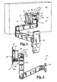
- a mounting device is depicted generally at 20 in the figures and generally includes a mounting device assembly 21 having a display interface 22, guide structure 24, and support structure 26.
- the display interface 22 of the mounting device 20 generally includes a frusto-spherical cup 28 which defines opening 30.
- Flange portion 32 extends laterally outward from outer edge 34 of frusto-spherical cup 28, and includes apertures 36 defined therein for receiving fasteners 37 (see particularly fig. 1) to secure display interface 22 to an electronic display device 38.
- the cup wall 33 of frusto-spherical cup 28 terminates at rear wall 35.
- Rear wall 35 has central bore 39 defined therein.
- the guide structure 24 of the mounting device 20 generally includes body portion 40, outer bearing 42, and inner bearing assembly 44.
- Body portion 40 is generally cup shaped and may be integrally formed from any suitable material such as metal or polymer, and generally includes outer circular wall 46 and inner circular wall 48 transversely coupled to rear wall 54.
- the outer circular wall 46 and inner circular wall 48 cooperatively define circular recess 50 therebetween.
- Central boss 52 is generally cylindrically shaped and extends forwardly from rear wall 54.
- An internally threaded bore 56 is defined coincident with the central axis 53 of the central boss 52.
- the outer bearing 42 of the guide structure 24 is generally ring shaped and is received in recess 50 of body portion 40.
- the axis of the outer bearing 42 is preferably in a coaxial disposition with a longitudinal axis 53 of the central boss 24 when the outer bearing 42 is integrated into the mounting device 20.
- the outer bearing 42 has a bearing surface 58 which may be conformingly shaped, such as by beveling, with outer surface 60 of cup wall 33 of the frusto-spherical cup 28.
- the outer bearing 42 has an opposed inner bearing surface 86 that bears against the rear wall 54.
- the inner bearing surface 86 may be conformingly shaped with an adjacent surface of the rear wall 54.
- Outer bearing 42 is generally annular, but may be discontinuous with a gap 62 defined between spaced apart ends 64, 66 (see particularly fig. 15).
- Set screw 68 extends through rear wall 54 of guide structure 24 and is received in gap 62 to inhibit rotation of outer bearing 42 in recess 50.
- An advantage of the discontinuous outer bearing 42 is that the gap 62 allows the outer bearing 42 to expand radially, thereby assisting in the seating of the outer bearing 42. Further, the discontinuous outer bearing 42 expands radially as the frictional biasing forces applied axially along axis 53 to the discontinuous outer bearing 42 are increased, thereby assisting in maintaining the desired amount of frictional biasing internal to the mounting device 20.
- Inner bearing assembly 44 generally includes inner bearing disc 70, washer 72 and threaded fastener 74 (see particularly figs. 11 and 12).
- Inner bearing disc 70 defines square aperture 76, which is received on flats 78 of central boss 52.
- the central boss 52 extends through the bore 39 defined in the rear wall 35 of the cup 28.
- Threaded fastener 74 extends through washer 72 and square aperture 76 and threads into bore 56 to secure inner bearing assembly 44 to body portion 40 with frusto-spherical cup 28 clamped between inner bearing disc 70 and outer bearing 42.
- friction adjustment control 80 enables selective frictional adjustment of the mounting device 20.
- friction adjustment control 80 generally includes biasing screw 82, which is threadedly received in a threaded aperture 83 defined in rear wall 54 of guide structure 24.
- biasing screw 82 loosening of biasing screw 82 will likewise result in less biasing clamping force applied to frusto-spherical cup 28 and a resultant lessening of frictional resistance to movement of frusto-spherical cup 28 relative to body portion 40.
- screw 82 extends through threaded bore 88 defined in outer wall 46 of body portion 40.
- Beveled surface 86 is provided on the outer bearing 42.
- Distal end 84 of screw 82 may be tapered conformingly with beveled surface 86.
- tapered distal end 84 of screw 82 slides downward along beveled surface 86 and forces outer bearing 42 forward against outer surface 60 of frusto-spherical cup 28.
- frusto-spherical cup 28 is thereby more tightly clamped between inner bearing disc 70 and outer bearing 72, increasing the frictional resistance to movement of frusto-spherical cup 28 relative to body portion 40.
- knob 90 may be coupled with screw 82 to enable fingertip adjustment of friction.
- mounting device 20 generally includes wall interface plate 120 which receives mounting device assembly 21 thereon.
- Wall interface plate 120 defines wedge shaped central column 122 having opposing rearward facing beveled surfaces 124.
- Rear face 126 of body portion 40 has a pair of spaced apart fastening structures 128, each having a forward facing beveled surface (not depicted) confronting the rearward facing beveled surfaces 124 of the wall interface plate 120.
- wall interface plate 120 may be mounted with rear face 129 confronting a wall surface 129a.
- mounting device assembly 21 may be detached from wall interface plate 120 by moving mounting device assembly 21 vertically relative to wall interface plate 120 and pulling outwardly until fastening structures 128 are disengaged from central column 122. Attachment of mounting device assembly 21 to wall interface plate 120 is accomplished by the reverse of this procedure.
- outer wall 46 of mounting device assembly 21 includes raised boss 130 at top side 132 of body 40.
- Boss 130 defines aperture 134 extending through from top surface 126 into recess 50.
- Upper shaft 138 of wedge element 140 is slidably received and guided in aperture 134 while lower wedge shaped portion 142 bears on beveled surface 86 of outer bearing 42.
- Screw 144 is threaded into aperture 134 and bears on upper shaft 138.
- Knob 146 is fixed to screw 144 to enable a user to thread screw 144 in and out with only finger pressure.
- the friction adjustment mechanism offers significant advantages over prior friction adjustment mechanisms.
- the weight of an electronic display attached to display interface 22 is borne primarily through fastener 74 to body portion 40 and does not tend to pull inner bearing disc 70 and outer bearing 42 apart.
- the weight of the electronic display does not tend to reduce the frictional clamping force on frusto-spherical cup 28 as in prior devices.
- the friction adjustment mechanism since the friction adjustment mechanism is not working to partially support the weight of the display device, the friction adjustment requires much less force for a comparable friction effect. This may enable application of sufficient force to virtually "lock" the display in position with only finger tightness of screw 82, 144.
- the split outer bearing 42 enables relatively smoother sliding movement of frusto-spherical cup 28 between inner bearing disc 70 and outer bearing 42.
- frusto-spherical cup 28 may be provided with a radius of curvature having a center generally coincident with the center of gravity of the display as described in U.S. Patent Application Nos.10/449,834 and 11/147,987 , previously incorporated herein by reference. This enables the electronic display to be substantially self-balancing, thereby requiring only minimal effort for positioning the display.
- Support structure 26 may be virtually any structure enabling attachment of guide structure 24 to a fixed structure such as a wall or column of a building.
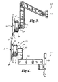
- support structure 26 generally includes pivot block 92, first arm 94, second arm 96, and wall plate 98.
- Pivot block 92 is attached to rear wall 54 of guide structure 24 with fasteners 100, which extend through apertures 102 in rear wall 54, and that are received in threaded bores 104 in pivot block 92.
- Vertical bore 106 is defined in pivot block 92 for receiving bolt 108.
- First arm 94 has a corresponding vertical bore (not depicted) which receives bolt 108 and enables horizontal pivoting of pivot block 92 and guide structure 24 relative to first arm 94.
- Nut 110 threads onto bolt 108 to secure pivot block 92 and first arm 94 together.
- Escutcheon 112 fits over bore 106 to provide a finished appearance to the upper surface of the device.
- Aperture 114 is provided in escutcheon 112 to enable bolt 108 to be accessed with a tool for tightening without requiring removal of escutcheon 112.
- First arm 94 is pivotally attached to second arm 96, and second arm 96 is pivotally attached to wall plate 98 using a similar arrangement to that described above.
- Spacer 116 may be provided between first arm 94 and second arm 96 to enable free movement of the arms without binding.
- guide structure 24 may be coupled with wall plate 98 using only one swing arm as depicted in Figs. 7-10, or directly pivotally attached to wall plate 98 as depicted in Figs. 16-18.
- any other support structure may be used to couple guide structure 24 to a fixed structure.
- Such alternative support structures may include, for example, any combination of swinging, folding, or articulating arms enabling positioning of guide structure 24 horizontally or vertically relative to the fixed structure.
Landscapes
- Engineering & Computer Science (AREA)
- General Engineering & Computer Science (AREA)
- Mechanical Engineering (AREA)
- Theoretical Computer Science (AREA)
- Computer Hardware Design (AREA)
- Human Computer Interaction (AREA)
- Physics & Mathematics (AREA)
- General Physics & Mathematics (AREA)
- Devices For Indicating Variable Information By Combining Individual Elements (AREA)
Applications Claiming Priority (1)
| Application Number | Priority Date | Filing Date | Title |
|---|---|---|---|
| US75618106P | 2006-01-04 | 2006-01-04 |
Publications (2)
| Publication Number | Publication Date |
|---|---|
| EP1806529A2 true EP1806529A2 (fr) | 2007-07-11 |
| EP1806529A3 EP1806529A3 (fr) | 2010-02-24 |
Family
ID=37898664
Family Applications (1)
| Application Number | Title | Priority Date | Filing Date |
|---|---|---|---|
| EP07290002A Withdrawn EP1806529A3 (fr) | 2006-01-04 | 2007-01-03 | Système de montage pour dispositif électronique de visualisation à écran plat |
Country Status (6)
| Country | Link |
|---|---|
| US (1) | US20070153459A1 (fr) |
| EP (1) | EP1806529A3 (fr) |
| JP (1) | JP2007206684A (fr) |
| CN (1) | CN101047043A (fr) |
| AU (1) | AU2007200023A1 (fr) |
| CA (1) | CA2572714C (fr) |
Cited By (1)
| Publication number | Priority date | Publication date | Assignee | Title |
|---|---|---|---|---|
| EP3220037A1 (fr) | 2016-03-18 | 2017-09-20 | Erard | Systeme support pour ecran plat et procede de mise en oeuvre |
Families Citing this family (42)
| Publication number | Priority date | Publication date | Assignee | Title |
|---|---|---|---|---|
| JP4713744B2 (ja) * | 1999-05-10 | 2011-06-29 | イノヴェイティヴ・オフィス・プロダクツ,インコーポレイテッド | 電子装置取着アーム装置 |
| US7152836B2 (en) | 2003-01-09 | 2006-12-26 | Csav, Inc. | Adjustable tilt mount |
| US7296774B2 (en) * | 2004-01-02 | 2007-11-20 | Clo Systems, Llc | Viewing angle adjustment system for a monitor |
| TWI281565B (en) * | 2005-06-27 | 2007-05-21 | Lite On Technology Corp | Display device with a supporter |
| US7487943B1 (en) * | 2006-01-05 | 2009-02-10 | Peerless Industries, Inc. | Dual arm mounting system with vertical adjustment feature |
| US8725845B2 (en) * | 2006-03-16 | 2014-05-13 | Exceptional Innovation Llc | Automation control system having a configuration tool |
| US8001219B2 (en) * | 2006-03-16 | 2011-08-16 | Exceptional Innovation, Llc | User control interface for convergence and automation system |
| US8209398B2 (en) * | 2006-03-16 | 2012-06-26 | Exceptional Innovation Llc | Internet protocol based media streaming solution |
| US8155142B2 (en) * | 2006-03-16 | 2012-04-10 | Exceptional Innovation Llc | Network based digital access point device |
| WO2007124453A2 (fr) | 2006-04-20 | 2007-11-01 | Exceptional Innovation Llc | Écran tactile pour système de convergence et d'automatisation |
| US7922139B2 (en) * | 2006-05-05 | 2011-04-12 | Milestone Av Technologies Llc | Adjustable projector mount |
| US7667968B2 (en) * | 2006-05-19 | 2010-02-23 | Exceptional Innovation, Llc | Air-cooling system configuration for touch screen |
| US7962130B2 (en) | 2006-11-09 | 2011-06-14 | Exceptional Innovation | Portable device for convergence and automation solution |
| KR100838591B1 (ko) * | 2007-01-08 | 2008-06-19 | 삼성전기주식회사 | 디스플레이 회동장치 |
| GB2452083A (en) * | 2007-08-24 | 2009-02-25 | Avf Group Ltd | A mounting bracket for a flat panel display |
| US20090266964A1 (en) * | 2008-04-29 | 2009-10-29 | Sung-Lin Hung | Retaining frame of display |
| EP2288960B1 (fr) | 2008-06-12 | 2012-12-26 | Milestone AV Technologies LLC | Interface de projecteur universelle avec alignement viable |
| CN101656036B (zh) * | 2009-07-29 | 2011-07-27 | 东莞宏威数码机械有限公司 | 手动微调机构 |
| USD635130S1 (en) | 2009-12-15 | 2011-03-29 | Milestone Av Technologies Llc | Mount for electronic display |
| USD814383S1 (en) * | 2010-05-07 | 2018-04-03 | Randy Mink | In-vehicle support |
| US9277812B2 (en) | 2010-07-08 | 2016-03-08 | Southco, Inc. | Display support with first and second arms and mechanism for maintaining constant orientation of the plane bisecting the range of rotation of the second arm relative to a support base |
| KR20120061395A (ko) * | 2010-12-03 | 2012-06-13 | 삼성모바일디스플레이주식회사 | 커버 유닛 및 이를 포함하는 표시 장치 |
| US9004430B2 (en) * | 2011-09-30 | 2015-04-14 | Imperial Stamping Corporation | Articulating mount for a display |
| WO2013127090A1 (fr) * | 2012-03-02 | 2013-09-06 | 湖州鸿迪科技发展有限公司 | Support de dispositif d'affichage |
| US9052057B2 (en) | 2012-10-02 | 2015-06-09 | Mw Products Llc | Flexible mount apparatus and system |
| CN103062588B (zh) * | 2012-11-30 | 2015-09-09 | 浙江一舟电子科技股份有限公司 | 一种电视机支架 |
| US9254051B2 (en) * | 2013-01-11 | 2016-02-09 | Atomic Design, Inc. | Display system |
| CN103953831A (zh) * | 2014-04-24 | 2014-07-30 | 宁波乐歌视讯科技股份有限公司 | 平板显示器支架 |
| CN105179900B (zh) * | 2015-09-01 | 2023-12-19 | 国家电网公司 | 户外仪器用快速安装支架 |
| US10317006B2 (en) | 2015-10-14 | 2019-06-11 | Wirepath Home Systems, Llc | Display mounts and related assemblies and methods |
| EP3875829A3 (fr) | 2016-03-07 | 2021-10-13 | Southco, Inc. | Ensemble bras de support d'écran pour monter un écran |
| CN107387983A (zh) * | 2017-09-06 | 2017-11-24 | 钦州学院 | 一种便于拆卸和组装的计算机显示器 |
| US10126787B1 (en) * | 2017-09-19 | 2018-11-13 | Hewlett-Packard Development Company, L.P. | Computing device mounting enclosures |
| US11746947B2 (en) * | 2020-02-07 | 2023-09-05 | Ricoh Company, Ltd. | Stand and stand system |
| CN112361163A (zh) * | 2020-11-28 | 2021-02-12 | 艾沃克有限公司 | 一种显示设备安装组件和显示设备安装装置 |
| US11934230B2 (en) | 2021-04-08 | 2024-03-19 | Apple Inc. | Reconfigurable stand ecosystem |
| US12372193B2 (en) * | 2021-04-08 | 2025-07-29 | Apple Inc. | Reconfigurable stand ecosystem |
| WO2022238712A1 (fr) | 2021-05-12 | 2022-11-17 | Colebrook Bosson & Saunders (Products) Limited | Tête d'inclinaison pour système de support d'affichage à charge élevée |
| CN120284062A (zh) * | 2021-12-22 | 2025-07-11 | 爱格升公司 | 工作站支撑组件 |
| CN117006356B (zh) * | 2022-04-29 | 2025-10-10 | 技嘉科技股份有限公司 | 显示器支架及其显示装置 |
| USD974534S1 (en) * | 2022-09-05 | 2023-01-03 | Guangdong Heshan Shanshui Sanitary Ware Co., Ltd. | Extension shower arm |
| USD975247S1 (en) * | 2022-09-05 | 2023-01-10 | Guangdong Heshan Shanshui Sanitary Ware Co., Ltd. | Extension shower arm |
Citations (1)
| Publication number | Priority date | Publication date | Assignee | Title |
|---|---|---|---|---|
| US6419196B1 (en) | 1996-06-07 | 2002-07-16 | Ergotron, Inc. | Pivot assembly and support system |
Family Cites Families (90)
| Publication number | Priority date | Publication date | Assignee | Title |
|---|---|---|---|---|
| US1320775A (en) * | 1919-11-04 | Lamp-stjppobt | ||
| US470802A (en) * | 1892-03-15 | Tripod-head for surveyors instruments | ||
| US36978A (en) * | 1862-11-18 | Improved washing-machine | ||
| US687183A (en) * | 1901-03-02 | 1901-11-19 | Max Pomper | Adjusting device for cameras, &c. |
| US737755A (en) * | 1902-08-26 | 1903-09-01 | Alfred Marceau | Tripod-head. |
| US916286A (en) * | 1908-01-10 | 1909-03-23 | William C Evans | Camera-tripod. |
| US1446164A (en) * | 1920-04-01 | 1923-02-20 | D Eyraud Louis | Universal mounting device |
| US1455784A (en) * | 1922-08-18 | 1923-05-22 | Edmunds & Jones Corp | Lamp bracket |
| US1646379A (en) * | 1924-12-22 | 1927-10-18 | Kales Stamping Company | Mirror support |
| US1846382A (en) * | 1929-06-22 | 1932-02-23 | Drem Products Corp | Camera tripod-clutch |
| US2214192A (en) * | 1939-04-17 | 1940-09-10 | Gordon G Burnett | Tripod adapter for panoramic photography |
| US3210106A (en) * | 1962-10-08 | 1965-10-05 | Trw Inc | Anti-unseating ball joint |
| US3211405A (en) * | 1964-01-30 | 1965-10-12 | Fey | Support for photographic instruments and the like |
| FR1535570A (fr) * | 1967-06-20 | 1968-08-09 | Palier auto-centreur perfectionné et procédé pour sa fabrication | |
| JPS4933146Y1 (fr) * | 1970-06-04 | 1974-09-07 | ||
| US4068961A (en) * | 1976-08-23 | 1978-01-17 | Milgo Electronic Corporation | Swivel joint |
| US4238802A (en) * | 1978-12-18 | 1980-12-09 | General Dynamics Corporation, Pomona Division | Differential drive rolling arc gimbal |
| IT1128801B (it) * | 1980-06-05 | 1986-06-04 | Olivetti & Co Spa | Dispositivo per orientare un apparecchiatura video rispetto ad una struttura fissa |
| GB2096234B (en) * | 1981-04-03 | 1985-02-20 | Mouldmaking Design Centre Ltd | Swivel mounting |
| GB2115479B (en) * | 1982-02-26 | 1985-10-02 | Plessey Co Plc | Supporting assembly |
| US4880191A (en) * | 1984-07-05 | 1989-11-14 | Unisys Corporation | Mounting arrangement for display terminal |
| US4621782A (en) * | 1984-07-26 | 1986-11-11 | At&T Bell Laboratories | Arrangement for mounting apparatus |
| DE8530047U1 (de) * | 1985-10-23 | 1986-05-15 | Ncr Corp., Dayton, Ohio | Ausziehbarer, höhenverstellbarer Schwenkarm für Bildschirmgeräte od. dgl. |
| US4768744A (en) * | 1986-08-27 | 1988-09-06 | Richard Leeds | Apparatus for supporting a load in a dynamically balanced condition |
| US4844387A (en) * | 1986-12-31 | 1989-07-04 | Hunt Holdings, Inc. | Monitor arm apparatus |
| US4836486A (en) * | 1987-04-16 | 1989-06-06 | Anthro Corporation | Adjustable support |
| US4836478A (en) * | 1987-10-15 | 1989-06-06 | Ergotron, Inc. | Suspension system for personal computers and monitors |
| US4923162A (en) * | 1988-09-19 | 1990-05-08 | Fleming Matthew C | Radiation shield swivel mount |
| US4989813A (en) * | 1989-11-29 | 1991-02-05 | Samsung Electron Devices Co., Ltd. | Supporting base for controlling height, swivel and inclination of display means |
| KR930000305Y1 (ko) * | 1989-11-30 | 1993-01-25 | 현대전자산업 주식회사 | 모니터의 회전 및 경사 각도 조절장치 |
| US5037050A (en) * | 1990-03-28 | 1991-08-06 | Digital Equipment Corporation | Interlocking assembly for adjustable mounting of a display unit |
| JP2708638B2 (ja) * | 1991-02-18 | 1998-02-04 | 三菱電機株式会社 | 回転架台 |
| DE4119508A1 (de) * | 1991-06-13 | 1992-12-17 | Loh Kg Rittal Werk | Drehkupplung fuer den anschluss eines steuergeraet-gehaeuses an einem tragarm oder einem winkelstueck |
| US5305114A (en) * | 1991-07-12 | 1994-04-19 | Matsushita Electric Industrial Co., Ltd. | Electronic blackboard apparatus |
| WO1993013463A1 (fr) * | 1992-01-03 | 1993-07-08 | Haines Kenneth A | Procedes de construction d'hologrammes a l'aide d'objets traites par ordinateur |
| JP3512435B2 (ja) * | 1992-02-24 | 2004-03-29 | スィロン エンジニアリング アンド マニュファクチュアリング コーポレイション | ボール結合リンク |
| GB2271273B (en) * | 1992-10-10 | 1997-03-05 | Haropa Prod Ltd | Support apparatus |
| US5277392A (en) * | 1992-10-19 | 1994-01-11 | Curtis Manufacturing Company, Inc. | Adjustable computer monitor arm and method |
| JP3064714B2 (ja) * | 1992-12-18 | 2000-07-12 | 三菱電機株式会社 | チルトスタンド |
| JP2654750B2 (ja) * | 1993-10-28 | 1997-09-17 | 日本コントロール工業株式会社 | 揺動機台 |
| JP3513987B2 (ja) * | 1994-06-13 | 2004-03-31 | 三星電子株式会社 | モニタースタンド |
| US5553820A (en) * | 1994-10-17 | 1996-09-10 | Rubbermaid Office Products Inc. | Adjustable monitor arm |
| KR0124727Y1 (ko) * | 1995-01-16 | 1998-09-15 | 구자홍 | 모니터에 사용되는 스피커 일체형 받침대 구조 |
| US5876008A (en) * | 1995-01-17 | 1999-03-02 | Ergotron, Inc. | Suspension system for video monitor or other equipment |
| NL9500300A (nl) * | 1995-02-17 | 1996-10-01 | Vogel S Holding Bv | Samenstel geschikt voor het ondersteunen van een elektronisch apparaat alsmede koppelstuk. |
| GB9503728D0 (en) * | 1995-02-24 | 1995-04-12 | Commercial Brians Limited | Improvements in and relating to support brackets |
| US5603478A (en) * | 1995-08-14 | 1997-02-18 | Wang; Daniel | Keyboard support |
| US5730408A (en) * | 1996-02-28 | 1998-03-24 | Knoll, Inc. | Independently adjustable mouse pad and keyboard support apparatus |
| US5743503A (en) * | 1996-03-08 | 1998-04-28 | Ergotron, Inc. | Computer suspension system |
| US5687939A (en) * | 1996-04-26 | 1997-11-18 | Moscovitch; Jerry | Dual display system |
| US5981841A (en) * | 1996-08-30 | 1999-11-09 | Monsanto Company | Early seed 5' regulatory sequence |
| TW321414U (en) * | 1997-05-07 | 1997-11-21 | Amtran Technology Co Ltd | Pivot-rotation device of flat-display panel |
| KR100255765B1 (ko) * | 1997-07-09 | 2000-05-01 | 구자홍 | 영상표시기기의 전후 조절 받침대 구조 |
| IL123261A (en) * | 1998-02-11 | 2000-12-06 | Barkan Lior | Support tray tilt mechanism |
| US6012693A (en) * | 1998-02-19 | 2000-01-11 | Ergotron, Inc. | Multi-function display mounting system |
| DE19839461C1 (de) * | 1998-08-29 | 1999-11-04 | Flm Gmbh Foto Licht Und Mestec | Stativkopf |
| US6343006B1 (en) * | 1998-11-20 | 2002-01-29 | Jerry Moscovitch | Computer display screen system and adjustable screen mount, and swinging screens therefor |
| US6138970A (en) * | 1999-05-07 | 2000-10-31 | Sohrt; Thomas M. | Universally adjustable mounting system |
| US6409134B1 (en) * | 1999-06-07 | 2002-06-25 | Innovative Office Products, Inc. | Arm apparatus for mounting electronic devices with cable management system |
| US6478274B1 (en) * | 1999-05-10 | 2002-11-12 | Innovative Office Products, Inc. | Arm apparatus for mounting electronic devices |
| US6505988B1 (en) * | 1999-06-02 | 2003-01-14 | Innovative Office Products, Inc. | Tilter for positioning electronic devices |
| US6189842B1 (en) * | 1999-06-21 | 2001-02-20 | Palo Alto Design Group | Tilt and swivel adjustment of flat panel display having detents for landscape and portrait positions and kickout for preventing contact between flat panel display and base |
| JP4460085B2 (ja) * | 1999-07-06 | 2010-05-12 | 出光興産株式会社 | 二酸化炭素冷媒用冷凍機油組成物 |
| US6273383B1 (en) * | 1999-09-27 | 2001-08-14 | Innovative Office Products, Inc. | Arm apparatus for mounting electronic devices, and method of making and using the same |
| DE60032802T2 (de) * | 1999-11-18 | 2007-10-11 | Claiteal Pty. Ltd., Kingsgrove | Tragarm für ein endgerät mit bildschirmanzeige |
| US6510049B2 (en) * | 2000-01-06 | 2003-01-21 | Rosen Products Llc | Adjustable display monitor unit |
| GB0026357D0 (en) * | 2000-10-27 | 2000-12-13 | Makex Ltd | Improvements in parallel link machine design |
| US6487274B2 (en) * | 2001-01-29 | 2002-11-26 | Siemens Medical Solutions Usa, Inc. | X-ray target assembly and radiation therapy systems and methods |
| FR2821902B1 (fr) * | 2001-03-12 | 2003-06-27 | Id Ind & Design | Dispositif de support pour un ecran plat a cristaux liquide |
| US6402109B1 (en) * | 2001-05-16 | 2002-06-11 | Chief Manufacturing, Inc. | Self-balancing mounting system for a flat panel display |
| TW564984U (en) * | 2001-08-30 | 2003-12-01 | Hannstar Display Corp | Liquid crystal display with a ball-and-socket joint |
| US6819550B2 (en) * | 2001-11-08 | 2004-11-16 | Apple Computer, Inc. | Computer controlled display device |
| US6454234B1 (en) * | 2001-11-14 | 2002-09-24 | Charles Westbrook | Apparatus for supporting and restraining electronic viewing monitors without penetrating fasteners |
| AU2002222629A1 (en) * | 2001-12-13 | 2003-06-23 | Murakami Corporation | Direction regulator of display |
| JPWO2003050787A1 (ja) * | 2001-12-13 | 2005-04-21 | 株式会社村上開明堂 | ディスプレイの昇降調整装置 |
| NL1019821C2 (nl) * | 2002-01-23 | 2003-07-30 | Vogel S Holding Bv | Inrichting voor het kantelbaar bevestigen van een beeldscherm aan een wand. |
| US20050242261A1 (en) * | 2002-02-25 | 2005-11-03 | Steris Inc | Surgical suspension system |
| US6905101B1 (en) * | 2002-06-11 | 2005-06-14 | Chief Manufacturing Inc. | Adjustable, self-balancing flat panel display mounting system |
| US6695270B1 (en) * | 2002-08-15 | 2004-02-24 | Ole Falk Smed | Flat panel display system |
| JP2004197849A (ja) * | 2002-12-19 | 2004-07-15 | Matsushita Electric Ind Co Ltd | 機器取付スタンド |
| JP4167506B2 (ja) * | 2003-02-03 | 2008-10-15 | 株式会社村上開明堂 | ディスプレイの方向調整装置 |
| JP2004302396A (ja) * | 2003-03-31 | 2004-10-28 | Umemoto Seisakusho:Kk | 自由雲台 |
| NL1023051C1 (nl) * | 2003-03-31 | 2004-10-01 | Vogel S Holding Bv | Inrichting geschikt voor het ondersteunen van een component. |
| DE50312154D1 (de) * | 2003-05-01 | 2010-01-07 | Philippe Vogt | Stativkopf |
| US7028961B1 (en) * | 2003-05-30 | 2006-04-18 | Csav, Inc. | Self-balancing adjustable flat panel mounting system |
| US7380760B2 (en) * | 2003-05-30 | 2008-06-03 | Csav, Inc. | Self-balancing adjustable mounting system with friction adjustment |
| JP4413061B2 (ja) * | 2004-04-09 | 2010-02-10 | 株式会社村上開明堂 | ディスプレイ保持装置 |
| US7658556B2 (en) * | 2005-01-07 | 2010-02-09 | Joseph Johnson | Panoramic camera mount |
| US20070090237A1 (en) * | 2005-10-07 | 2007-04-26 | Hsu Chen J | Camera tripod |
| US7281693B2 (en) * | 2005-12-29 | 2007-10-16 | Ta-Ching Chou | Ball head assembly with anti-escape mechanism for a tripod |
-
2006
- 2006-12-29 US US11/648,180 patent/US20070153459A1/en not_active Abandoned
-
2007
- 2007-01-02 CA CA2572714A patent/CA2572714C/fr active Active
- 2007-01-03 AU AU2007200023A patent/AU2007200023A1/en not_active Abandoned
- 2007-01-03 EP EP07290002A patent/EP1806529A3/fr not_active Withdrawn
- 2007-01-04 JP JP2007000061A patent/JP2007206684A/ja active Pending
- 2007-01-04 CN CNA2007100879409A patent/CN101047043A/zh active Pending
Patent Citations (1)
| Publication number | Priority date | Publication date | Assignee | Title |
|---|---|---|---|---|
| US6419196B1 (en) | 1996-06-07 | 2002-07-16 | Ergotron, Inc. | Pivot assembly and support system |
Cited By (1)
| Publication number | Priority date | Publication date | Assignee | Title |
|---|---|---|---|---|
| EP3220037A1 (fr) | 2016-03-18 | 2017-09-20 | Erard | Systeme support pour ecran plat et procede de mise en oeuvre |
Also Published As
| Publication number | Publication date |
|---|---|
| AU2007200023A1 (en) | 2007-07-19 |
| CA2572714A1 (fr) | 2007-07-04 |
| CA2572714C (fr) | 2012-06-12 |
| JP2007206684A (ja) | 2007-08-16 |
| EP1806529A3 (fr) | 2010-02-24 |
| CN101047043A (zh) | 2007-10-03 |
| US20070153459A1 (en) | 2007-07-05 |
Similar Documents
| Publication | Publication Date | Title |
|---|---|---|
| EP1806529A2 (fr) | Système de montage pour dispositif électronique de visualisation à écran plat | |
| AU2023202873B2 (en) | Tilt mechanism | |
| US7380760B2 (en) | Self-balancing adjustable mounting system with friction adjustment | |
| EP3286480B1 (fr) | Bras de support articulé à articulation à basculement et frottement améliorée | |
| US7810773B2 (en) | Support arm structure with elastic force adjustment arrangement | |
| US7014157B2 (en) | Friction cylinder for a support device | |
| US9316346B2 (en) | Support system | |
| JP6038156B2 (ja) | 支持装置の摩擦調節機構 | |
| US20190368651A1 (en) | Articulating support arm with improved tilter and friction joint | |
| US20090173860A1 (en) | Mounting system for flat panel display | |
| US20050284997A1 (en) | Flat screen monitor desktop support | |
| GB2464149A (en) | An assembly to attach a display device to a display device support | |
| JP2002300496A (ja) | 電子デバイスを取り付けるための、ケーブル管理システムを備えたアーム装置 | |
| US7421813B2 (en) | Display device having an adjustable counterweight structure | |
| US11193527B2 (en) | Supporting device | |
| US20100001153A1 (en) | Cam lock for cantilever mounting device | |
| US5915658A (en) | Base seat structure for liquid crystal type display | |
| EP1696169B1 (fr) | Structure de support réglable pour écran de visualisation | |
| CN223228160U (zh) | 一种显示器支架 | |
| JP4318285B2 (ja) | ヒンジ及びヒンジユニット | |
| JPH061667U (ja) | 調整蝶番 | |
| KR19990041119U (ko) | 화면확대장치 | |
| AU2011201926A1 (en) | Monitor Support |
Legal Events
| Date | Code | Title | Description |
|---|---|---|---|
| PUAI | Public reference made under article 153(3) epc to a published international application that has entered the european phase |
Free format text: ORIGINAL CODE: 0009012 |
|
| AK | Designated contracting states |
Kind code of ref document: A2 Designated state(s): AT BE BG CH CY CZ DE DK EE ES FI FR GB GR HU IE IS IT LI LT LU LV MC NL PL PT RO SE SI SK TR |
|
| AX | Request for extension of the european patent |
Extension state: AL BA HR MK YU |
|
| RAP1 | Party data changed (applicant data changed or rights of an application transferred) |
Owner name: CSAV I LLC |
|
| RAP1 | Party data changed (applicant data changed or rights of an application transferred) |
Owner name: MILESTONE AV TECHNOLOGIES LLC |
|
| PUAL | Search report despatched |
Free format text: ORIGINAL CODE: 0009013 |
|
| AK | Designated contracting states |
Kind code of ref document: A3 Designated state(s): AT BE BG CH CY CZ DE DK EE ES FI FR GB GR HU IE IS IT LI LT LU LV MC NL PL PT RO SE SI SK TR |
|
| AX | Request for extension of the european patent |
Extension state: AL BA HR MK RS |
|
| AKY | No designation fees paid | ||
| REG | Reference to a national code |
Ref country code: DE Ref legal event code: 8566 |
|
| STAA | Information on the status of an ep patent application or granted ep patent |
Free format text: STATUS: THE APPLICATION IS DEEMED TO BE WITHDRAWN |
|
| 18D | Application deemed to be withdrawn |
Effective date: 20100825 |