EP1806570A2 - Procede et dispositif d'equilibrage de rotor - Google Patents
Procede et dispositif d'equilibrage de rotor Download PDFInfo
- Publication number
- EP1806570A2 EP1806570A2 EP05802863A EP05802863A EP1806570A2 EP 1806570 A2 EP1806570 A2 EP 1806570A2 EP 05802863 A EP05802863 A EP 05802863A EP 05802863 A EP05802863 A EP 05802863A EP 1806570 A2 EP1806570 A2 EP 1806570A2
- Authority
- EP
- European Patent Office
- Prior art keywords
- rotor
- axis
- imbalance
- balanced body
- unit
- Prior art date
- Legal status (The legal status is an assumption and is not a legal conclusion. Google has not performed a legal analysis and makes no representation as to the accuracy of the status listed.)
- Withdrawn
Links
Images


Classifications
-
- G—PHYSICS
- G01—MEASURING; TESTING
- G01M—TESTING STATIC OR DYNAMIC BALANCE OF MACHINES OR STRUCTURES; TESTING OF STRUCTURES OR APPARATUS, NOT OTHERWISE PROVIDED FOR
- G01M1/00—Testing static or dynamic balance of machines or structures
- G01M1/14—Determining imbalance
- G01M1/16—Determining imbalance by oscillating or rotating the body to be tested
- G01M1/22—Determining imbalance by oscillating or rotating the body to be tested and converting vibrations due to imbalance into electric variables
Definitions
- the present invention relates to the technique for dynamic balancing of rotating bodies and may be used for measuring and correcting forces generated by unbalance of rotors, in particular, rigid rotors.
- a method for rotor balancing provides for the measurement of rotor imbalance parameters (amount of out-of-balance mass, radius and angle of its center disposition relative to a rotor axis) by means of determining two unbalance vectors (unbalance is a vector quantity that is equal to the unbalanced mass multiplied by its center radius-vector relative to the axis) that are arranged in two arbitrary planes being perpendicular to a rotor axis. These planes are called as imbalance datum planes or imbalance correction planes (see, for example, M.E. Levit, V.M. Ryzhenkov "Balancing of Parts and Units", Moscow, Mechanical Engineering, 1986 ).
- This method is characterized by the rotor to be driven in rotary motion and by the measurement of dynamic loads applied in the support lateral planes to be symmetrically relative to the rotor axis (e.g. US Patent No. 6 430 992, 73/66, 2002 ).
- a drawback with this method consists in complexity of processing of parameters to be measured for the determination of imbalance in each datum plane.
- the present invention relates to a fundamentally different method of balancing that is characterized by a complex motion of a rotor. While using sufficiently simple techniques this method makes it possible to improve the accuracy of measuring imbalance parameters.
- Improvement of this method is aimed at improving a balancing accuracy at the expense of decreasing the rotor angular oscillations affecting parameters to be measured.
- This method like the above one, consists in imparting oscillatory motion to the rotor relative to a fixed point located on the rotor axis and measuring the rotor angular oscillation amplitude and phase, by which rotor imbalance parameters can be judged in one of the imbalance planes.
- a reference system of measurements that makes it possible to decrease influence on the measured parameters of the rotor angular oscillations relative to its axis is configured.
- the reference system is configured by means of using a balanced body that is coaxial with the rotor; said body being set in motion simultaneously with the rotor. This method may be considered as the closest prior art with respect to the present invention.
- the closest prior art device to be used for the claimed method is a device known from the Russian Patent No. 2105962, G01M1/38, 1993 and designed for using the balancing method based on imparting the oscillatory motion to the rotor.
- This device comprises a bed plate, a shaft with a spherical support fit at its one end and joined to a drive shaft with a variable eccentric and being set up on the rotor and installed inside the balanced body on the elastically flexible flat part that makes it possible to offset relative to the balanced body axis, as well as unbalance control sensors, a reference signal sensor and a sensor output signal processing unit.
- the signal processing unit comprises a pulse sequence generator with its input connected to the reference signal sensor, a binary counter, a trigger, a storage register block, a decoder and an imbalance angular coordinate and value indicator.
- the above unit elements are interconnected in accordance with the circuit providing measurement of imbalance parameters.
- the technical effect to be achieved when using the present invention is to improve accuracy of measurements of the rotor angular oscillation amplitude and phase at the expense of decreasing the influence (in the ideal case - at the expense of eliminating thereof) of angular oscillations of the balanced body relative to its axis on parameters to be measured.
- the method that comprises imparting of oscillatory motion to a rotor and to a coaxial balanced body relative to a fixed point selected at the common axis of the rotor and the balanced body, and measuring amplitude and phase of the rotor angular oscillations by which rotor imbalance parameters are judged, additionally comprises a new procedure, namely: simultaneously in each time of determining unbalance in the plane passing through the above fixed point, forces opposing angular oscillations of the balanced body relative to an axis are exerted to the balanced body tangentially.
- the measured amplitude and phase of angular oscillations are used to judge imbalance parameters in other imbalance datum plane.
- imbalance parameters in the imbalance datum plane passing through the above fixed point are specified.
- the technical effect obtainable when using the claimed device consists in a high balancing accuracy to be provided by applying simple technical means that do not distort the results of measuring the rotor imbalance parameters relative to the balanced body.
- a device comprising a bed plate, a balanced body and a shaft designed to mount on it the rotor and fit inside the balanced body on a flexible support to move along the balanced body axis, said body being provided at one end with a spherical support and joined to a drive shaft with a variable eccentric, and also imbalance measurement sensors, a reference signal sensor and a sensor output signal processing unit.
- the device further comprises an additional flexible support for the balanced body, said support being fixed on the bed plate and opposing its angular oscillations in the plane passing through said spherical support center on the bed plate on which the other end of the balanced body is mounted.
- Ease of using the device when determining imbalance parameters in the both imbalance datum planes is achieved by the fact that the rotor is mounted on the drive shaft to move along its axis and fix at two positions such that in the first position one of the rotor imbalance datum plane passes through the spherical support center and in the second position the plane is displaced with respect to the spherical support center.
- the additional flexible support is made as a diaphragm rigidly mounted along the perimeter in the bed plate.
- the imbalance sensors are installed such that centers of their sensing elements are arranged symmetrically relative to the balanced body axis on the same diameter, and their terminals are connected such that with an angular displacement of the balanced body sensor outputs are summed up and with a displacement in the plane perpendicular to the balanced body axis they are subtracted. This allows, with the rotor residual oscillations that take place in the plane perpendicular to the rotor axis, to ensure compensation of the influence of these oscillations on parameters to be measured.
- the signal-processing unit comprises a control unit, an AD converter, a storage unit, a multiplier unit, a subtracting unit, an amplitude and phase measuring unit and an imbalance angular coordinate and rate indicator.
- a control unit input is connected to a reference signal sensor and an output - to driving inputs of the AD converter, the storage unit and the amplitude and phase measuring unit.
- Outputs of the imbalance value sensor are connected to an input of the AD converter signal, connected with its output to the inputs of the storage unit and amplitude and phase measuring unit, as well as to a first input of the subtracting unit, connected with its second input to the output of the storage unit via the multiplier unit.
- An output of the subtracting unit is connected to an input of the multiplier unit, connected with its output to the input of the imbalance angular coordinate and rate indicator.
- the rotor balancing device comprises a bed plate 1, in which a balanced body 4 is mounted with its one end on a flexible support 2 by means of a spherical support 3.
- a spherical support center 3 operates as a fixed point, relative to which the balanced body 4 makes oscillatory motion.
- a shaft 7 of a rotor 8 is coaxially fit inside the balanced body 4 on axis-centering flexible supports 5 and 6.
- the other end of the balanced body 4 is connected by means of a spherical support 9 to a variable eccentric 10 mounted on a drive shaft 11 installed on the bed plate 1.
- the rotor 8 is installed to move along its axis by the size h and fix in two positions such that in the first position one of the imbalance datum plane, e.g.
- the size h is a distance that is selected on the basis of ease of measurement. It may be less than the distance between the rotor imbalance datum planes or equal to it.
- a flexible support 2 is used to prevent angular oscillations of the balanced body 4 relative to the bed plate 1 in the planes that are perpendicular to body axis 4. Any support (springs, elastic needles, torsion bar etc) may be used as a flexible support. But it is preferred to use the diaphragm rigidly mounted along the perimeter of the bed plate 1, as this method of mounting allows increasing inertia rate of the balanced body 4 thus additionally improving accuracy of imbalance parameters.
- the supports 5 and 6 permit the shaft 7 of the rotor 8 to run on its axis limiting its angular oscillations and allow the rotor 8 to return in its initial position when the drive 11 stops.
- An embodiment shown in Figure 2 depicts the supports 5 and 6 as needles 12.
- Imbalance sensors 13 and 14 are located on a platform 15 that is mounted on the balanced body 4 in the plane perpendicular to its axis (Fig. 3). Sensing elements of the sensors 13 and 14 are arranged symmetrically to the axis of the balanced body 4 and fit at the same diameter. If, instead of the sensors 13 and 14, magnetic induction sensors are used, their armatures are mounted on connecting elements 16 that are rigidly joined to the shaft 7 of the rotor 8.
- Output terminals of the sensors 13 and 14 are such that the output signals of the sensors 13 and 14 are summed up if an angular oscillation of the balanced body 4 relative to the axis takes place, and are subtracted, if the axis of the balanced body 4 is misaligned in the plane that is perpendicular to its axis.
- a variable eccentric 10 (Fig.1) is connected to a reference signal sensor 17.
- Indicator lamps 18 depicting an imbalance rate angular coordinate to be found on the rotor 8 are arranged along the perimeter of the bed plate 1.
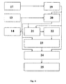
- a signal processing unit (Fig. 4) from the outputs of the sensors 13 and 14 comprises a control unit 19, an AD converter 20, a storage unit 21, a multiplier unit 22, a subtracting unit 23, an amplitude and phase measuring unit 24 and an imbalance angular coordinate and value indicator 25.
- the input of the control unit 19 is connected to the reference signal sensor 17 and the output is connected to the driving points of the AD converter 20, the storage unit 21 and the amplitude and phase control unit 24.
- the outputs of the imbalance rate sensors 13 and 14 are connected to the signal input of the AD converter 20, connected with its output to the inputs of the storage unit 21 and the amplitude and phase measuring unit 24.
- the first input of the subtracting unit 23 is connected to the output of the AD converter 20 and the second input - to the output of the multiplier unit 22.
- the output of the unit 23 is connected to the indicator 25 via the unit 24.
- the rotor 8 and the balanced body 4 are mounted on the shaft 7 in the eccentric 10 on the support such that their axis is oriented at an acute angle to a vertical axis passing through the center of the spherical support 3 (see Fig. 1).
- the shaft of the drive 11 is brought to run, thereby oscillatory motion is imparted to the shaft 7 of the rotor 8 and to the balanced body 4 with respect to the center of the support 3 in the plane that is perpendicular to the drawing plane.
- the torque drives the rotor 8 together with the shaft 7 about its axis (ideally, when the rotor 8 is balanced, it makes oscillatory motion about its axis without angular oscillations).
- the rotor 8 performs oscillations in the plane that is perpendicular to its axis, and an amplitude of these oscillations is much higher than the amplitude of oscillations that are due to imbalance.
- angular oscillations of the rotor 8 affect the body 4, but simultaneous exerting of forces at each moment to each point of the balanced body 4 in the plane passing through the center of the support 3, said forces being directed tangentially to the body, results in compensation of the influence of the flexible elements, i.e. in increase (removal) of angular oscillations of the balanced body 4 relative to its axis.
- This signal is converted in the AD converter 20 into digital one and comes simultaneously to the signal input of the amplitude and phase control unit 24 and to the storage unit 21.
- the imbalance rate and upper plane angular coordinate data are generated at the output of the unit 24.
- the indicator 25 indicates the obtained data.
- the storage unit 21 memorizes snap data of signal S 1 .
- the output signals of the sensors 13 and 14 are processed as follows.
- the signal, which specifies measurement of the digital signal amplitude and phase that comes from the output of the subtracting unit 23 is sent from the output of the control unit 19 to the amplitude and phase control unit 24.
- This unit subtracts signal S from the output of the AD converter 20 and signal S 1 from the output of the storage unit 21 multiplied by scale factor k in the multiplier unit 22.
- Scale unit k accepts a signal amplitude changing rates coming from sensors 13 and 14 that are specified by imbalance of the rotor 8 in the upper datum plane.
- This signal comes to the second signal input of the amplitude and phase measuring unit 24 and the indicator 25 that indicates the imbalance data of the rotor 8 in the lower datum plane.
- the indicator 25 may simultaneously indicate imbalance parameters that can be found in the both datum planes.
- the use of the claimed method allows measurement of the rotor imbalance parameters with high accuracy in two imbalance datum planes.
- This method is easy in operation and does not need large costs for its implementation.
- the method may be used both in industrial and household conditions.
Landscapes
- Physics & Mathematics (AREA)
- General Physics & Mathematics (AREA)
- Testing Of Balance (AREA)
Applications Claiming Priority (2)
| Application Number | Priority Date | Filing Date | Title |
|---|---|---|---|
| RU2004129262/28A RU2270985C1 (ru) | 2004-10-06 | 2004-10-06 | Способ и устройство для балансировки ротора |
| PCT/RU2005/000499 WO2006038835A2 (fr) | 2004-10-06 | 2005-10-05 | Procede et dispositif d'equilibrage de rotor |
Publications (2)
| Publication Number | Publication Date |
|---|---|
| EP1806570A2 true EP1806570A2 (fr) | 2007-07-11 |
| EP1806570A4 EP1806570A4 (fr) | 2008-10-22 |
Family
ID=36114407
Family Applications (1)
| Application Number | Title | Priority Date | Filing Date |
|---|---|---|---|
| EP05802863A Withdrawn EP1806570A4 (fr) | 2004-10-06 | 2005-10-05 | Procede et dispositif d'equilibrage de rotor |
Country Status (8)
| Country | Link |
|---|---|
| US (1) | US7856877B2 (fr) |
| EP (1) | EP1806570A4 (fr) |
| JP (1) | JP2008516226A (fr) |
| CN (1) | CN101040178B (fr) |
| AU (1) | AU2005292753A1 (fr) |
| BR (1) | BRPI0515817A (fr) |
| RU (1) | RU2270985C1 (fr) |
| WO (1) | WO2006038835A2 (fr) |
Cited By (1)
| Publication number | Priority date | Publication date | Assignee | Title |
|---|---|---|---|---|
| CN102095556A (zh) * | 2010-12-28 | 2011-06-15 | 孝感松林国际计测器有限公司 | 高分离比静偶动平衡测量装置 |
Families Citing this family (11)
| Publication number | Priority date | Publication date | Assignee | Title |
|---|---|---|---|---|
| RU2426976C2 (ru) * | 2008-05-27 | 2011-08-20 | Александр Николаевич Николаев | Способ и устройство для автоматической балансировки ротора |
| RU2426082C1 (ru) * | 2010-03-15 | 2011-08-10 | Александр Николаевич Николаев | Способ и устройство для балансировки роторов |
| CN103234003B (zh) * | 2013-04-27 | 2015-02-04 | 东北大学 | 一种采用热辐射控制的转子系统自动平衡装置 |
| CN103216573B (zh) * | 2013-05-06 | 2015-09-23 | 东北大学 | 一种利用辐射加热抑制转子振动的方法 |
| CN103364139A (zh) * | 2013-07-30 | 2013-10-23 | 南车株洲电机有限公司 | 转子动平衡试验方法、动平衡试验设备及其保温装置 |
| IL240316B (en) * | 2015-08-03 | 2018-10-31 | Technion Res & Dev Foundation | Method and system for parametric amplification |
| EP3179611B1 (fr) * | 2015-12-10 | 2018-06-27 | Skf Magnetic Mechatronics | Procédé d'équilibrage permettant l'équilibrage à grande vitesse d'un rotor d'une machine rotative |
| CN106153253A (zh) * | 2016-06-16 | 2016-11-23 | 上海交通大学 | 盘形零件质心测量装置及测量方法 |
| CN108226647B (zh) * | 2018-04-13 | 2024-05-24 | 南方电网科学研究院有限责任公司 | 一种对电力线接入点阻抗的测量装置 |
| CN110940460B (zh) * | 2019-12-27 | 2024-12-13 | 无锡超通智能制造技术研究院有限公司 | 微型涡喷发动机转子的超精密激光自动去重动平衡机 |
| FR3160240A1 (fr) * | 2024-03-14 | 2025-09-19 | Safran Aircraft Engines | Système et procédé d’équilibrage d’une turbine de banc d’essai |
Family Cites Families (16)
| Publication number | Priority date | Publication date | Assignee | Title |
|---|---|---|---|---|
| GB361544A (en) * | 1929-10-22 | 1931-11-26 | British Thomson Houston Co Ltd | Improvements in and relating to balancing machines for rotating bodies |
| US3158038A (en) * | 1961-12-18 | 1964-11-24 | Gen Electric | Rotor vibration reducing device |
| SU396575A1 (ru) * | 1971-12-28 | 1973-08-29 | Балансировочное устройство | |
| US4285240A (en) * | 1980-01-11 | 1981-08-25 | Fmc Corporation | Wheel unbalance measurement system and method |
| DE3176938D1 (en) * | 1981-09-10 | 1988-12-22 | Schenck Ag Carl | Apparatus and method for transferring a measured angular location of unbalance to the circumference of a rotor |
| EP0150274B1 (fr) | 1981-09-10 | 1988-11-17 | Carl Schenck Ag | Dispositif et procédé pour reporter l'angle du balourd mesuré sur la circonférence d'un rotor |
| US4930348A (en) * | 1988-11-25 | 1990-06-05 | Balance Engineering Corporation | Vertical balancing machine with cartridge assembly |
| DE4133787C2 (de) * | 1991-10-11 | 2002-06-20 | Schenck Rotec Gmbh | Auswuchtverfahren zur testgewichtslauffreien Ermittlung der Ausgleichsmassen für einen elastischen Rotor auf einer kraftmessenden Auswuchtmaschine und Einrichtung zur Durchführung des Verfahrens |
| DE4225195A1 (de) * | 1992-07-30 | 1994-02-03 | Hofmann Maschinenbau Gmbh | Verfahren zur Messung von Rund- und/oder Planlaufabweichungen eines Rotors |
| DE4240787C2 (de) * | 1992-12-04 | 1997-09-11 | Hofmann Maschinenbau Gmbh | Verfahren und Vorrichtung zum dynamischen Auswuchten eines Rotors |
| RU2105962C1 (ru) * | 1993-07-01 | 1998-02-27 | Борис Авраамович Малев | Станок для балансировки роторов |
| BR9908457B1 (pt) * | 1998-09-02 | 2010-11-30 | dispositivo para medição de forças, que são produzidas por uma massa desbalanceada de um rotor. | |
| CN1269504A (zh) * | 1999-04-06 | 2000-10-11 | 黄震西 | 转子不平衡量两点测定法 |
| ITTO20011218A1 (it) * | 2001-12-24 | 2003-06-24 | Redat Spa | Sistema per la misura dello squilibrio di rotori ,particolarmente di turbine per turbocompressori automobilistici. |
| RU2225602C2 (ru) * | 2002-04-29 | 2004-03-10 | Акционерное общество открытого типа "Научно-исследовательский технологический институт" (АООТ "НИТИ-ТЕСАР") | Устройство для динамической балансировки изделий |
| CN100344896C (zh) * | 2003-02-14 | 2007-10-24 | 重庆大学 | 转子平衡中平衡块的精确定位方法 |
-
2004
- 2004-10-06 RU RU2004129262/28A patent/RU2270985C1/ru not_active IP Right Cessation
-
2005
- 2005-10-05 CN CN2005800343034A patent/CN101040178B/zh not_active Expired - Fee Related
- 2005-10-05 US US11/576,003 patent/US7856877B2/en not_active Expired - Fee Related
- 2005-10-05 BR BRPI0515817-6A patent/BRPI0515817A/pt not_active Application Discontinuation
- 2005-10-05 AU AU2005292753A patent/AU2005292753A1/en not_active Abandoned
- 2005-10-05 WO PCT/RU2005/000499 patent/WO2006038835A2/fr not_active Ceased
- 2005-10-05 EP EP05802863A patent/EP1806570A4/fr not_active Withdrawn
- 2005-10-05 JP JP2007535626A patent/JP2008516226A/ja active Pending
Cited By (1)
| Publication number | Priority date | Publication date | Assignee | Title |
|---|---|---|---|---|
| CN102095556A (zh) * | 2010-12-28 | 2011-06-15 | 孝感松林国际计测器有限公司 | 高分离比静偶动平衡测量装置 |
Also Published As
| Publication number | Publication date |
|---|---|
| WO2006038835A3 (fr) | 2006-06-15 |
| RU2270985C1 (ru) | 2006-02-27 |
| CN101040178B (zh) | 2010-10-27 |
| US7856877B2 (en) | 2010-12-28 |
| US20080060436A1 (en) | 2008-03-13 |
| WO2006038835A2 (fr) | 2006-04-13 |
| CN101040178A (zh) | 2007-09-19 |
| AU2005292753A1 (en) | 2006-04-13 |
| EP1806570A4 (fr) | 2008-10-22 |
| BRPI0515817A (pt) | 2008-08-05 |
| JP2008516226A (ja) | 2008-05-15 |
Similar Documents
| Publication | Publication Date | Title |
|---|---|---|
| Thearle | Dynamic balancing of rotating machinery in the field | |
| EP1806570A2 (fr) | Procede et dispositif d'equilibrage de rotor | |
| KR20130094203A (ko) | 운동을 감지하기 위한 마이크로 자이로스코프 | |
| US6631640B2 (en) | Method and apparatus for measuring dynamic balance | |
| JP2009236880A (ja) | 基準加振機 | |
| RU2426976C2 (ru) | Способ и устройство для автоматической балансировки ротора | |
| RU2426082C1 (ru) | Способ и устройство для балансировки роторов | |
| US3805623A (en) | Balancing apparatus for measurement of want of balance | |
| RU2382999C1 (ru) | Способ динамической балансировки ротора | |
| JPH0359432A (ja) | ねじり加振を利用した動釣合い試験機 | |
| RU2105962C1 (ru) | Станок для балансировки роторов | |
| RU2432557C2 (ru) | Стенд комплексного определения массово-инерционных характеристик осесимметричных роторов | |
| US3813948A (en) | Apparatus for detecting unbalance in a wheel | |
| SU712708A1 (ru) | Способ определени дисбаланса ротора | |
| RU2299409C1 (ru) | Станок для балансировки роторов | |
| RU2593676C1 (ru) | Балансировочный станок и низкочастотная колебательная система для его реализации | |
| KR20020063646A (ko) | 관성 모멘트 측정 기구 | |
| SU1247702A1 (ru) | Способ балансировки деталей вращени и устройство дл его осуществлени | |
| SU1144015A1 (ru) | Балансировочный станок | |
| SU1015261A1 (ru) | Способ градуировки рычажных аэродинамических весов со схемой управлени на переменном токе | |
| RU2077038C1 (ru) | Способ определения величины и угла дисбаланса | |
| JP4049931B2 (ja) | つりあい試験装置における固有振動数の設定方法 | |
| RU2101689C1 (ru) | Способ вибрационной балансировки роторов и колебательная система балансировочного станка для его осуществления | |
| RU2319127C2 (ru) | Способ балансировки роторов | |
| SU1060958A1 (ru) | Способ балансировки роторов |
Legal Events
| Date | Code | Title | Description |
|---|---|---|---|
| PUAI | Public reference made under article 153(3) epc to a published international application that has entered the european phase |
Free format text: ORIGINAL CODE: 0009012 |
|
| 17P | Request for examination filed |
Effective date: 20070425 |
|
| AK | Designated contracting states |
Kind code of ref document: A2 Designated state(s): AT BE BG CH CY CZ DE DK EE ES FI FR GB GR HU IE IS IT LI LT LU LV MC NL PL PT RO SE SI SK TR |
|
| DAX | Request for extension of the european patent (deleted) | ||
| A4 | Supplementary search report drawn up and despatched |
Effective date: 20080923 |
|
| 17Q | First examination report despatched |
Effective date: 20090114 |
|
| STAA | Information on the status of an ep patent application or granted ep patent |
Free format text: STATUS: THE APPLICATION IS DEEMED TO BE WITHDRAWN |
|
| 18D | Application deemed to be withdrawn |
Effective date: 20090501 |