EP1806594A2 - Système à ultrasons et méthode de visualisation d'images ultrasonores - Google Patents
Système à ultrasons et méthode de visualisation d'images ultrasonores Download PDFInfo
- Publication number
- EP1806594A2 EP1806594A2 EP07000170A EP07000170A EP1806594A2 EP 1806594 A2 EP1806594 A2 EP 1806594A2 EP 07000170 A EP07000170 A EP 07000170A EP 07000170 A EP07000170 A EP 07000170A EP 1806594 A2 EP1806594 A2 EP 1806594A2
- Authority
- EP
- European Patent Office
- Prior art keywords
- ultrasound images
- ultrasound
- cycle
- ecg
- images
- Prior art date
- Legal status (The legal status is an assumption and is not a legal conclusion. Google has not performed a legal analysis and makes no representation as to the accuracy of the status listed.)
- Withdrawn
Links
Images



Classifications
-
- A—HUMAN NECESSITIES
- A61—MEDICAL OR VETERINARY SCIENCE; HYGIENE
- A61B—DIAGNOSIS; SURGERY; IDENTIFICATION
- A61B8/00—Diagnosis using ultrasonic, sonic or infrasonic waves
- A61B8/08—Clinical applications
-
- H—ELECTRICITY
- H02—GENERATION; CONVERSION OR DISTRIBUTION OF ELECTRIC POWER
- H02G—INSTALLATION OF ELECTRIC CABLES OR LINES, OR OF COMBINED OPTICAL AND ELECTRIC CABLES OR LINES
- H02G7/00—Overhead installations of electric lines or cables
- H02G7/05—Suspension arrangements or devices for electric cables or lines
- H02G7/053—Suspension clamps and clips for electric overhead lines not suspended to a supporting wire
-
- A—HUMAN NECESSITIES
- A61—MEDICAL OR VETERINARY SCIENCE; HYGIENE
- A61B—DIAGNOSIS; SURGERY; IDENTIFICATION
- A61B8/00—Diagnosis using ultrasonic, sonic or infrasonic waves
- A61B8/46—Ultrasonic, sonic or infrasonic diagnostic devices with special arrangements for interfacing with the operator or the patient
- A61B8/461—Displaying means of special interest
- A61B8/463—Displaying means of special interest characterised by displaying multiple images or images and diagnostic data on one display
-
- H—ELECTRICITY
- H01—ELECTRIC ELEMENTS
- H01B—CABLES; CONDUCTORS; INSULATORS; SELECTION OF MATERIALS FOR THEIR CONDUCTIVE, INSULATING OR DIELECTRIC PROPERTIES
- H01B17/00—Insulators or insulating bodies characterised by their form
- H01B17/02—Suspension insulators; Strain insulators
-
- A—HUMAN NECESSITIES
- A61—MEDICAL OR VETERINARY SCIENCE; HYGIENE
- A61B—DIAGNOSIS; SURGERY; IDENTIFICATION
- A61B8/00—Diagnosis using ultrasonic, sonic or infrasonic waves
- A61B8/54—Control of the diagnostic device
- A61B8/543—Control of the diagnostic device involving acquisition triggered by a physiological signal
-
- G—PHYSICS
- G01—MEASURING; TESTING
- G01S—RADIO DIRECTION-FINDING; RADIO NAVIGATION; DETERMINING DISTANCE OR VELOCITY BY USE OF RADIO WAVES; LOCATING OR PRESENCE-DETECTING BY USE OF THE REFLECTION OR RERADIATION OF RADIO WAVES; ANALOGOUS ARRANGEMENTS USING OTHER WAVES
- G01S7/00—Details of systems according to groups G01S13/00, G01S15/00, G01S17/00
- G01S7/52—Details of systems according to groups G01S13/00, G01S15/00, G01S17/00 of systems according to group G01S15/00
- G01S7/52017—Details of systems according to groups G01S13/00, G01S15/00, G01S17/00 of systems according to group G01S15/00 particularly adapted to short-range imaging
- G01S7/52053—Display arrangements
- G01S7/52057—Cathode ray tube displays
- G01S7/52074—Composite displays, e.g. split-screen displays; Combination of multiple images or of images and alphanumeric tabular information
Definitions
- the present invention generally relates to ultrasound systems, and more particularly to an ultrasound system and a method of displaying ultrasound images relating to the periodic motion of an object.
- the ultrasound diagnostic system has become an important and popular diagnostic tool due to its wide range of applications. Specifically, due to its non-invasive and non-destructive nature, the ultrasound diagnostic system has been extensively used in the medical profession. Modern high-performance ultrasound diagnostic systems and techniques are commonly used to produce two or three-dimensional (2D or 3D) diagnostic images of a target object.
- the ultrasound diagnostic system generally uses a probe including an array transducer having a plurality of transducer elements to transmit and receive ultrasound signals.
- the ultrasound diagnostic system forms ultrasound images of the internal structures of the target object by electrically exciting the transducer elements to generate ultrasound pulses that travel into the target object.
- the ultrasound pulses produce ultrasound echoes since they are reflected from a discontinuous surface of acoustic impedance of the internal structure, which appears as discontinuities to the propagating ultrasound pulses.
- Various ultrasound echoes return to the array transducer and are converted into electrical signals, which are amplified and processed to produce ultrasound data for forming an image of the internal structure of the target object.
- the heart acts as a pump to circulate blood throughout the entire body.
- the heart continually repeats to contract and relax.
- the pumping action of the heart is performed by the contraction of cardiac muscles.
- small electric currents are generated so as to flow into the body.
- Such generated currents change the electric potential distribution on the surface of the body.
- Electrocardiogram is a recording of such electric currents generated during the heart activity, which are measured at an appropriate portion on the surface of the body and then amplified.
- a diagnosis may determine that a patient is normal even though he or she has a disease. Further, a diagnosis may determine that a patient is not normal even though he or she has no disease. Thus, there is a strong need for an accurate analysis method of analyzing the results of electrocardiogram measurements.
- FIG. 1 illustrates an ultrasound system constructed in accordance with one embodiment of the present invention
- FIG. 1 illustrates an ultrasound system, which is constructed in accordance with one embodiment of the present invention. However, it should be expressly noted herein that other arrangements may also be used.
- an ultrasound system 100 of the present invention may include an ultrasound diagnostic unit 10, a first memory 20, an ECG signal supply unit 30, an ECG cycle setting unit 40, a processor 50, a second memory 60, a digital scan converter (DSC) 70, a display unit 80 and a user interface 90.
- the first memory 20 and the second memory 60 can be configured with a single memory.
- the ultrasound diagnostic unit 10 transmits ultrasound signals to an object in a periodic motion (e.g., heart) and provides ultrasound images at every moment of receiving signals reflected from the heart.
- the ultrasound image can be a 2 or 3-dimensional image.
- the ultrasound images provided by the ultrasound diagnostic unit 10 are stored in the first memory 20 together with the reception times of the receive signals.
- the ECG signal supply unit 30 receives electrocardiogram (ECG) signals from an ECG measuring apparatus and provides the ECG signals to the ECG cycle setting unit 40.
- ECG signals can be digital signals, which are indicative of the magnitudes of electric potential.
- the ECG cycle setting unit 40 analyzes the ECG signals during a predetermined time period to set an ECG cycle, wherein said predetermined time period preferably ranges from 0.05 seconds to 3 seconds from a first reception time of ECG signals.
- the ECG cycle can be measured by using various methods. For example, in an ECG graph shown in FIG. 2, one ECG cycle can be set to a time interval between neighboring peaks A1 and A2 or between neighboring points B1 and B2 in the same phase.
- the ECG cycle setting unit 40 transmits time information of start and end of each ECG cycle to the processor 50.
- the processor 50 sets the ultrasound images stored in the first memory 20, which have the reception times approximately equal to the start and end of each ECG cycle, to be a start image and an end image of each ECG cycle.
- the processor 50 In order to display n x n ultrasound images in each ECG cycle, the processor 50 counts the number of ultrasound images in each ECG cycle. If the number of ultrasound images within an ECG cycle is larger than n x n, then extra ultrasound images (except n x n ultrasound images) are removed. In such a case, differences between the reception times of the receive signals corresponding to the neighboring ultrasound images are calculated. Then, one of the neighboring ultrasound images having the smallest difference is first removed. Thereafter, extra ultrasound images are removed in such a manner that one of the neighboring ultrasound images having the smallest difference among the remaining ultrasound images is removed.
- n x n the number of ultrasound images in an ECG cycle is smaller than n x n
- supplementary ultrasound images are produced to make n x n ultrasound images within an ECG cycle.
- differences between the reception times of the receive signals corresponding to the neighboring ultrasound images are calculated.
- a new ultrasound image between the neighboring ultrasound images having the largest difference is interpolated and supplementary ultrasound images are produced in such a manner.
- the second memory 60 stores n x n ultrasound images corresponding to each ECG cycle, which are provided from the processor 50.
- FIG. 3 shows an example of storing n x n ultrasound images within an ECG cycle in the second memory 60.
- the DSC 70 scan-converts the ultrasound images, which are stored in the second memory 60, and then provides the scan-converted ultrasound images to the display unit 80.
- the display unit 80 displays the scan-converted ultrasound images provided from the DSC 70 such that n x n ultrasound images within one cycle of the heartbeat are displayed in the same time.
- the display unit 80 may display the ultrasound images within one cycle of the heartbeat on the screen of the display unit 80, which is divided into n x n areas, respectively. Also, the display unit 80 may display the respective ultrasound images on the screens of the n x n monitors.
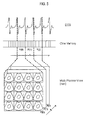
- FIG. 5 shows an example of ECG waveforms as well as storing and displaying the ultrasound images. In FIG. 5, the ultrasound images in the respective ECG cycles P(0), P(1), P(2) ... are stored and displayed at specified time intervals.
- the user can select one image (e.g., m th ultrasound image) among the n x n ultrasound images through the user interface 90 such as a mouse, track ball and the like.
- one image e.g., m th ultrasound image
- the user interface 90 such as a mouse, track ball and the like.
- the processor 50 compares the m th ultrasound images in the neighboring ECG cycles. For example, the processor 50 may compare the m th ultrasound image in the ECG cycle P(0) with the m th ultrasound image in the ECG cycle P(1). Further, the processor 50 may compare the m th ultrasound image in the ECG cycle P(1) with the m th ultrasound image in the ECG cycle P(2). Then, a comparison result can be provided to the user through the display unit 80.
- the user can obtain a more accurate diagnosis regarding the heart disease based on the ECG and ultrasound images provided from the ultrasound system.
- An embodiment may be achieved in whole or in part by an ultrasound system, which includes: a ultrasound diagnostic unit for transmitting ultrasound signals to a target object in a periodic motion and forming ultrasound images based on receive signals reflected from the target object, wherein the ultrasound diagnostic unit is further configured to provide reception times of the receive signals corresponding to the ultrasound images; a first storage unit for storing the ultrasound images provided from the ultrasound diagnostic unit together with the reception times of the receive signals; a cycle setting unit for setting a cycle of motion of the target object; a processor for selecting the ultrasound images within a specific cycle among the ultrasound images stored in the first storage unit based on the reception times of the receive signals corresponding to the ultrasound images and start and end times of the specific cycle provided from the cycle setting unit, wherein the processor is configured to form an equal number of ultrasound images within each cycle based on the number of the selected ultrasound images; a second storage unit for storing the ultrasound images within each cycle provided from the processor in a regular order; and a display unit for simultaneously displaying the ultrasound images within each cycle.
- any reference in this specification to "one embodiment,” “an embodiment,” “example embodiment,” etc. means that a particular feature, structure or characteristic described in connection with the embodiment is included in at least one embodiment of the invention.
- the appearances of such phrases in various places in the specification are not necessarily all referring to the same embodiment.
Landscapes
- Life Sciences & Earth Sciences (AREA)
- Health & Medical Sciences (AREA)
- Biomedical Technology (AREA)
- Biophysics (AREA)
- Nuclear Medicine, Radiotherapy & Molecular Imaging (AREA)
- Pathology (AREA)
- Radiology & Medical Imaging (AREA)
- Engineering & Computer Science (AREA)
- Physics & Mathematics (AREA)
- Heart & Thoracic Surgery (AREA)
- Medical Informatics (AREA)
- Molecular Biology (AREA)
- Surgery (AREA)
- Animal Behavior & Ethology (AREA)
- General Health & Medical Sciences (AREA)
- Public Health (AREA)
- Veterinary Medicine (AREA)
- Ultra Sonic Daignosis Equipment (AREA)
- Measurement And Recording Of Electrical Phenomena And Electrical Characteristics Of The Living Body (AREA)
Applications Claiming Priority (1)
| Application Number | Priority Date | Filing Date | Title |
|---|---|---|---|
| KR1020060001591A KR100867588B1 (ko) | 2006-01-06 | 2006-01-06 | 대상체의 운동주기에 대응시켜 초음파 영상을디스플레이하는 초음파 시스템 및 방법 |
Publications (2)
| Publication Number | Publication Date |
|---|---|
| EP1806594A2 true EP1806594A2 (fr) | 2007-07-11 |
| EP1806594A3 EP1806594A3 (fr) | 2007-12-12 |
Family
ID=38031265
Family Applications (1)
| Application Number | Title | Priority Date | Filing Date |
|---|---|---|---|
| EP07000170A Withdrawn EP1806594A3 (fr) | 2006-01-06 | 2007-01-05 | Système à ultrasons et méthode de visualisation d'images ultrasonores |
Country Status (4)
| Country | Link |
|---|---|
| US (1) | US20070161895A1 (fr) |
| EP (1) | EP1806594A3 (fr) |
| JP (1) | JP2007181706A (fr) |
| KR (1) | KR100867588B1 (fr) |
Cited By (2)
| Publication number | Priority date | Publication date | Assignee | Title |
|---|---|---|---|---|
| WO2013140358A1 (fr) * | 2012-03-23 | 2013-09-26 | Koninklijke Philips N.V. | Système d'imagerie pour l'imagerie d'un objet se déplaçant de façon périodique |
| CN107708570A (zh) * | 2015-07-10 | 2018-02-16 | 深圳迈瑞生物医疗电子股份有限公司 | 一种监护系统、方法及装置 |
Families Citing this family (6)
| Publication number | Priority date | Publication date | Assignee | Title |
|---|---|---|---|---|
| KR101071015B1 (ko) * | 2007-12-27 | 2011-10-06 | 삼성메디슨 주식회사 | 초음파 진단 장치 및 영상 디스플레이 방법 |
| JP5472891B2 (ja) | 2008-01-21 | 2014-04-16 | 株式会社東芝 | 医用画像処理装置 |
| KR101028719B1 (ko) * | 2008-09-30 | 2011-04-14 | 주식회사 바이오넷 | 전기심장영동 트리거를 이용한 가상 고 해상도 및 고 프레임률 씨네(cine) 표현 방법 및 장치 |
| KR101797042B1 (ko) | 2015-05-15 | 2017-11-13 | 삼성전자주식회사 | 의료 영상 합성 방법 및 장치 |
| KR102182489B1 (ko) * | 2016-07-26 | 2020-11-24 | 지멘스 메디컬 솔루션즈 유에스에이, 인크. | 초음파 영상을 생성하는 방법, 초음파 시스템 및 기록매체 |
| US10905402B2 (en) * | 2016-07-27 | 2021-02-02 | Canon Medical Systems Corporation | Diagnostic guidance systems and methods |
Family Cites Families (10)
| Publication number | Priority date | Publication date | Assignee | Title |
|---|---|---|---|---|
| US5619995A (en) * | 1991-11-12 | 1997-04-15 | Lobodzinski; Suave M. | Motion video transformation system and method |
| KR100330855B1 (ko) * | 1999-02-09 | 2002-04-03 | 이민화 | 초단수신신호의 저장과 저장된 데이터의 재사용이 가능한 디지털 초음파영상장치 |
| US6231508B1 (en) * | 1999-03-05 | 2001-05-15 | Atl Ultrasound | Ultrasonic diagnostic imaging system with digital video image marking |
| JP4763883B2 (ja) * | 2000-09-18 | 2011-08-31 | 株式会社東芝 | 超音波診断装置 |
| US6730032B2 (en) * | 2001-03-05 | 2004-05-04 | Matsushita Electric Industrial Co. | Ultrasonic diagnostic device and image processing device |
| JP4672176B2 (ja) * | 2001-05-14 | 2011-04-20 | 株式会社日立メディコ | 超音波診断装置 |
| JP3986866B2 (ja) * | 2002-03-29 | 2007-10-03 | 松下電器産業株式会社 | 画像処理装置及び超音波診断装置 |
| US20040066389A1 (en) * | 2002-10-03 | 2004-04-08 | Koninklijke Philips Electronics N.V | System and method for automatically generating a series of ultrasound images each representing the same point in a physiologic periodic waveform |
| US20050033123A1 (en) * | 2003-07-25 | 2005-02-10 | Siemens Medical Solutions Usa, Inc. | Region of interest methods and systems for ultrasound imaging |
| US7794398B2 (en) * | 2003-09-29 | 2010-09-14 | Koninklijke Philips Electronics N.V. | Real-time volumetric bi-plane ultrasound imaging and quantification |
-
2006
- 2006-01-06 KR KR1020060001591A patent/KR100867588B1/ko not_active Expired - Lifetime
-
2007
- 2007-01-05 US US11/620,360 patent/US20070161895A1/en not_active Abandoned
- 2007-01-05 JP JP2007000824A patent/JP2007181706A/ja active Pending
- 2007-01-05 EP EP07000170A patent/EP1806594A3/fr not_active Withdrawn
Cited By (3)
| Publication number | Priority date | Publication date | Assignee | Title |
|---|---|---|---|---|
| WO2013140358A1 (fr) * | 2012-03-23 | 2013-09-26 | Koninklijke Philips N.V. | Système d'imagerie pour l'imagerie d'un objet se déplaçant de façon périodique |
| US10130341B2 (en) | 2012-03-23 | 2018-11-20 | Koninklijke Philips N.V. | Imaging system for imaging a periodically moving object |
| CN107708570A (zh) * | 2015-07-10 | 2018-02-16 | 深圳迈瑞生物医疗电子股份有限公司 | 一种监护系统、方法及装置 |
Also Published As
| Publication number | Publication date |
|---|---|
| EP1806594A3 (fr) | 2007-12-12 |
| JP2007181706A (ja) | 2007-07-19 |
| US20070161895A1 (en) | 2007-07-12 |
| KR100867588B1 (ko) | 2008-11-10 |
| KR20070074027A (ko) | 2007-07-12 |
Similar Documents
| Publication | Publication Date | Title |
|---|---|---|
| EP2437666B1 (fr) | Procede et appareil de mesure de la contractilite cardiaque | |
| US9697634B2 (en) | Ultrasound image processing to render three-dimensional images from two-dimensional images | |
| EP3092951B1 (fr) | Procédé et appareil de synthèse d'images médicales | |
| EP2168495B1 (fr) | Échographe et procédé de contrôle d'échographe | |
| US20100286523A1 (en) | Ultrasound diagnostic system and method for displaying doppler spectrum images of multiple sample volumes | |
| JP5231768B2 (ja) | 超音波診断装置および超音波診断装置のデータ処理プログラム | |
| CN102088913A (zh) | 心脏同步性和生成力的超声评估 | |
| WO2004034910A1 (fr) | Systeme et procede permettant d'ameliorer l'affichage d'images diagnostiques | |
| JP2022529603A (ja) | 心臓エラストグラフィのための取得トリガのためのシステム及び方法 | |
| JP2013523243A (ja) | 超音波画像及びecgデータの統合された表示 | |
| US8323198B2 (en) | Spatial and temporal alignment for volume rendering in medical diagnostic ultrasound | |
| JP2012250083A (ja) | 超音波診断装置および超音波診断装置のデータ処理プログラム | |
| EP1806594A2 (fr) | Système à ultrasons et méthode de visualisation d'images ultrasonores | |
| JPH11221210A (ja) | 超音波診断装置 | |
| US20240057968A1 (en) | System and method for measuring total blood volume with ultrasound | |
| JP2002336255A (ja) | 超音波診断装置 | |
| JP2014076365A (ja) | 医療画像表示方法及びその装置、並びにユーザ・インターフェース画面生成方法 | |
| JP7194501B2 (ja) | 心電波形のタイミング検出装置及び医用画像診断装置 | |
| US12527550B2 (en) | System and method for simultaneous acquisition of pulsed-wave doppler and color doppler for retrospective analysis of cardiovascular function | |
| CN113633311A (zh) | 瞬时弹性测量方法及设备 | |
| KR100879916B1 (ko) | 초음파 영상을 형성하는 초음파 시스템 및 방법 | |
| JP2004180974A (ja) | 超音波診断支援システム | |
| HK1167304B (en) | Method and apparatus for measuring heart contractility |
Legal Events
| Date | Code | Title | Description |
|---|---|---|---|
| PUAI | Public reference made under article 153(3) epc to a published international application that has entered the european phase |
Free format text: ORIGINAL CODE: 0009012 |
|
| AK | Designated contracting states |
Kind code of ref document: A2 Designated state(s): AT BE BG CH CY CZ DE DK EE ES FI FR GB GR HU IE IS IT LI LT LU LV MC NL PL PT RO SE SI SK TR |
|
| AX | Request for extension of the european patent |
Extension state: AL BA HR MK YU |
|
| PUAL | Search report despatched |
Free format text: ORIGINAL CODE: 0009013 |
|
| AK | Designated contracting states |
Kind code of ref document: A3 Designated state(s): AT BE BG CH CY CZ DE DK EE ES FI FR GB GR HU IE IS IT LI LT LU LV MC NL PL PT RO SE SI SK TR |
|
| AX | Request for extension of the european patent |
Extension state: AL BA HR MK YU |
|
| 17P | Request for examination filed |
Effective date: 20080311 |
|
| 17Q | First examination report despatched |
Effective date: 20080417 |
|
| AKX | Designation fees paid |
Designated state(s): DE FR IT |
|
| STAA | Information on the status of an ep patent application or granted ep patent |
Free format text: STATUS: THE APPLICATION IS DEEMED TO BE WITHDRAWN |
|
| 18D | Application deemed to be withdrawn |
Effective date: 20190801 |