EP1807190B1 - Reacteur et procede de realisation de reactions catalytiques endothermiques ou exothermiques - Google Patents
Reacteur et procede de realisation de reactions catalytiques endothermiques ou exothermiques Download PDFInfo
- Publication number
- EP1807190B1 EP1807190B1 EP05803822.5A EP05803822A EP1807190B1 EP 1807190 B1 EP1807190 B1 EP 1807190B1 EP 05803822 A EP05803822 A EP 05803822A EP 1807190 B1 EP1807190 B1 EP 1807190B1
- Authority
- EP
- European Patent Office
- Prior art keywords
- heat transfer
- transfer tubes
- tubes
- reactor
- catalyst
- Prior art date
- Legal status (The legal status is an assumption and is not a legal conclusion. Google has not performed a legal analysis and makes no representation as to the accuracy of the status listed.)
- Expired - Lifetime
Links
Images
Classifications
-
- C—CHEMISTRY; METALLURGY
- C01—INORGANIC CHEMISTRY
- C01B—NON-METALLIC ELEMENTS; COMPOUNDS THEREOF; METALLOIDS OR COMPOUNDS THEREOF NOT COVERED BY SUBCLASS C01C
- C01B3/00—Hydrogen; Gaseous mixtures containing hydrogen; Separation of hydrogen from mixtures containing it; Purification of hydrogen; Reversible storage of hydrogen
- C01B3/02—Production of hydrogen; Production of gaseous mixtures containing hydrogen
- C01B3/32—Production of hydrogen; Production of gaseous mixtures containing hydrogen by reaction of gaseous or liquid organic compounds with gasifying agents, e.g. water, carbon dioxide or air
- C01B3/34—Production of hydrogen; Production of gaseous mixtures containing hydrogen by reaction of gaseous or liquid organic compounds with gasifying agents, e.g. water, carbon dioxide or air by reaction of hydrocarbons with gasifying agents
- C01B3/38—Production of hydrogen; Production of gaseous mixtures containing hydrogen by reaction of gaseous or liquid organic compounds with gasifying agents, e.g. water, carbon dioxide or air by reaction of hydrocarbons with gasifying agents using catalysts
- C01B3/384—Production of hydrogen; Production of gaseous mixtures containing hydrogen by reaction of gaseous or liquid organic compounds with gasifying agents, e.g. water, carbon dioxide or air by reaction of hydrocarbons with gasifying agents using catalysts with external heating of the catalyst
-
- B—PERFORMING OPERATIONS; TRANSPORTING
- B01—PHYSICAL OR CHEMICAL PROCESSES OR APPARATUS IN GENERAL
- B01J—CHEMICAL OR PHYSICAL PROCESSES, e.g. CATALYSIS OR COLLOID CHEMISTRY; THEIR RELEVANT APPARATUS
- B01J8/00—Chemical or physical processes in general, conducted in the presence of fluids and solid particles; Apparatus for such processes
- B01J8/02—Chemical or physical processes in general, conducted in the presence of fluids and solid particles; Apparatus for such processes with stationary particles, e.g. in fixed beds
-
- B—PERFORMING OPERATIONS; TRANSPORTING
- B01—PHYSICAL OR CHEMICAL PROCESSES OR APPARATUS IN GENERAL
- B01J—CHEMICAL OR PHYSICAL PROCESSES, e.g. CATALYSIS OR COLLOID CHEMISTRY; THEIR RELEVANT APPARATUS
- B01J8/00—Chemical or physical processes in general, conducted in the presence of fluids and solid particles; Apparatus for such processes
-
- B—PERFORMING OPERATIONS; TRANSPORTING
- B01—PHYSICAL OR CHEMICAL PROCESSES OR APPARATUS IN GENERAL
- B01J—CHEMICAL OR PHYSICAL PROCESSES, e.g. CATALYSIS OR COLLOID CHEMISTRY; THEIR RELEVANT APPARATUS
- B01J8/00—Chemical or physical processes in general, conducted in the presence of fluids and solid particles; Apparatus for such processes
- B01J8/008—Details of the reactor or of the particulate material; Processes to increase or to retard the rate of reaction
-
- B—PERFORMING OPERATIONS; TRANSPORTING
- B01—PHYSICAL OR CHEMICAL PROCESSES OR APPARATUS IN GENERAL
- B01J—CHEMICAL OR PHYSICAL PROCESSES, e.g. CATALYSIS OR COLLOID CHEMISTRY; THEIR RELEVANT APPARATUS
- B01J8/00—Chemical or physical processes in general, conducted in the presence of fluids and solid particles; Apparatus for such processes
- B01J8/02—Chemical or physical processes in general, conducted in the presence of fluids and solid particles; Apparatus for such processes with stationary particles, e.g. in fixed beds
- B01J8/0207—Chemical or physical processes in general, conducted in the presence of fluids and solid particles; Apparatus for such processes with stationary particles, e.g. in fixed beds the fluid flow within the bed being predominantly horizontal
- B01J8/0221—Chemical or physical processes in general, conducted in the presence of fluids and solid particles; Apparatus for such processes with stationary particles, e.g. in fixed beds the fluid flow within the bed being predominantly horizontal in a cylindrical shaped bed
-
- B—PERFORMING OPERATIONS; TRANSPORTING
- B01—PHYSICAL OR CHEMICAL PROCESSES OR APPARATUS IN GENERAL
- B01J—CHEMICAL OR PHYSICAL PROCESSES, e.g. CATALYSIS OR COLLOID CHEMISTRY; THEIR RELEVANT APPARATUS
- B01J8/00—Chemical or physical processes in general, conducted in the presence of fluids and solid particles; Apparatus for such processes
- B01J8/02—Chemical or physical processes in general, conducted in the presence of fluids and solid particles; Apparatus for such processes with stationary particles, e.g. in fixed beds
- B01J8/0242—Chemical or physical processes in general, conducted in the presence of fluids and solid particles; Apparatus for such processes with stationary particles, e.g. in fixed beds the fluid flow within the bed being predominantly vertical
- B01J8/025—Chemical or physical processes in general, conducted in the presence of fluids and solid particles; Apparatus for such processes with stationary particles, e.g. in fixed beds the fluid flow within the bed being predominantly vertical in a cylindrical shaped bed
-
- B—PERFORMING OPERATIONS; TRANSPORTING
- B01—PHYSICAL OR CHEMICAL PROCESSES OR APPARATUS IN GENERAL
- B01J—CHEMICAL OR PHYSICAL PROCESSES, e.g. CATALYSIS OR COLLOID CHEMISTRY; THEIR RELEVANT APPARATUS
- B01J8/00—Chemical or physical processes in general, conducted in the presence of fluids and solid particles; Apparatus for such processes
- B01J8/02—Chemical or physical processes in general, conducted in the presence of fluids and solid particles; Apparatus for such processes with stationary particles, e.g. in fixed beds
- B01J8/0285—Heating or cooling the reactor
-
- C—CHEMISTRY; METALLURGY
- C01—INORGANIC CHEMISTRY
- C01B—NON-METALLIC ELEMENTS; COMPOUNDS THEREOF; METALLOIDS OR COMPOUNDS THEREOF NOT COVERED BY SUBCLASS C01C
- C01B3/00—Hydrogen; Gaseous mixtures containing hydrogen; Separation of hydrogen from mixtures containing it; Purification of hydrogen; Reversible storage of hydrogen
- C01B3/02—Production of hydrogen; Production of gaseous mixtures containing hydrogen
- C01B3/32—Production of hydrogen; Production of gaseous mixtures containing hydrogen by reaction of gaseous or liquid organic compounds with gasifying agents, e.g. water, carbon dioxide or air
- C01B3/34—Production of hydrogen; Production of gaseous mixtures containing hydrogen by reaction of gaseous or liquid organic compounds with gasifying agents, e.g. water, carbon dioxide or air by reaction of hydrocarbons with gasifying agents
- C01B3/38—Production of hydrogen; Production of gaseous mixtures containing hydrogen by reaction of gaseous or liquid organic compounds with gasifying agents, e.g. water, carbon dioxide or air by reaction of hydrocarbons with gasifying agents using catalysts
-
- B—PERFORMING OPERATIONS; TRANSPORTING
- B01—PHYSICAL OR CHEMICAL PROCESSES OR APPARATUS IN GENERAL
- B01J—CHEMICAL OR PHYSICAL PROCESSES, e.g. CATALYSIS OR COLLOID CHEMISTRY; THEIR RELEVANT APPARATUS
- B01J2208/00—Processes carried out in the presence of solid particles; Reactors therefor
- B01J2208/00008—Controlling the process
- B01J2208/00017—Controlling the temperature
- B01J2208/00106—Controlling the temperature by indirect heat exchange
- B01J2208/00115—Controlling the temperature by indirect heat exchange with heat exchange elements inside the bed of solid particles
- B01J2208/00132—Tubes
-
- B—PERFORMING OPERATIONS; TRANSPORTING
- B01—PHYSICAL OR CHEMICAL PROCESSES OR APPARATUS IN GENERAL
- B01J—CHEMICAL OR PHYSICAL PROCESSES, e.g. CATALYSIS OR COLLOID CHEMISTRY; THEIR RELEVANT APPARATUS
- B01J2208/00—Processes carried out in the presence of solid particles; Reactors therefor
- B01J2208/00008—Controlling the process
- B01J2208/00017—Controlling the temperature
- B01J2208/00106—Controlling the temperature by indirect heat exchange
- B01J2208/00168—Controlling the temperature by indirect heat exchange with heat exchange elements outside the bed of solid particles
- B01J2208/00212—Plates; Jackets; Cylinders
-
- B—PERFORMING OPERATIONS; TRANSPORTING
- B01—PHYSICAL OR CHEMICAL PROCESSES OR APPARATUS IN GENERAL
- B01J—CHEMICAL OR PHYSICAL PROCESSES, e.g. CATALYSIS OR COLLOID CHEMISTRY; THEIR RELEVANT APPARATUS
- B01J2219/00—Chemical, physical or physico-chemical processes in general; Their relevant apparatus
- B01J2219/02—Apparatus characterised by their chemically-resistant properties
- B01J2219/025—Apparatus characterised by their chemically-resistant properties characterised by the construction materials of the reactor vessel proper
- B01J2219/0277—Metal based
- B01J2219/0286—Steel
-
- C—CHEMISTRY; METALLURGY
- C01—INORGANIC CHEMISTRY
- C01B—NON-METALLIC ELEMENTS; COMPOUNDS THEREOF; METALLOIDS OR COMPOUNDS THEREOF NOT COVERED BY SUBCLASS C01C
- C01B2203/00—Integrated processes for the production of hydrogen or synthesis gas
- C01B2203/02—Processes for making hydrogen or synthesis gas
- C01B2203/0205—Processes for making hydrogen or synthesis gas containing a reforming step
- C01B2203/0227—Processes for making hydrogen or synthesis gas containing a reforming step containing a catalytic reforming step
- C01B2203/0233—Processes for making hydrogen or synthesis gas containing a reforming step containing a catalytic reforming step the reforming step being a steam reforming step
-
- C—CHEMISTRY; METALLURGY
- C01—INORGANIC CHEMISTRY
- C01B—NON-METALLIC ELEMENTS; COMPOUNDS THEREOF; METALLOIDS OR COMPOUNDS THEREOF NOT COVERED BY SUBCLASS C01C
- C01B2203/00—Integrated processes for the production of hydrogen or synthesis gas
- C01B2203/02—Processes for making hydrogen or synthesis gas
- C01B2203/0205—Processes for making hydrogen or synthesis gas containing a reforming step
- C01B2203/0227—Processes for making hydrogen or synthesis gas containing a reforming step containing a catalytic reforming step
- C01B2203/0244—Processes for making hydrogen or synthesis gas containing a reforming step containing a catalytic reforming step the reforming step being an autothermal reforming step, e.g. secondary reforming processes
-
- C—CHEMISTRY; METALLURGY
- C01—INORGANIC CHEMISTRY
- C01B—NON-METALLIC ELEMENTS; COMPOUNDS THEREOF; METALLOIDS OR COMPOUNDS THEREOF NOT COVERED BY SUBCLASS C01C
- C01B2203/00—Integrated processes for the production of hydrogen or synthesis gas
- C01B2203/08—Methods of heating or cooling
- C01B2203/0805—Methods of heating the process for making hydrogen or synthesis gas
- C01B2203/0838—Methods of heating the process for making hydrogen or synthesis gas by heat exchange with exothermic reactions, other than by combustion of fuel
- C01B2203/0844—Methods of heating the process for making hydrogen or synthesis gas by heat exchange with exothermic reactions, other than by combustion of fuel the non-combustive exothermic reaction being another reforming reaction as defined in groups C01B2203/02 - C01B2203/0294
-
- C—CHEMISTRY; METALLURGY
- C01—INORGANIC CHEMISTRY
- C01B—NON-METALLIC ELEMENTS; COMPOUNDS THEREOF; METALLOIDS OR COMPOUNDS THEREOF NOT COVERED BY SUBCLASS C01C
- C01B2203/00—Integrated processes for the production of hydrogen or synthesis gas
- C01B2203/14—Details of the flowsheet
- C01B2203/141—At least two reforming, decomposition or partial oxidation steps in parallel
-
- Y—GENERAL TAGGING OF NEW TECHNOLOGICAL DEVELOPMENTS; GENERAL TAGGING OF CROSS-SECTIONAL TECHNOLOGIES SPANNING OVER SEVERAL SECTIONS OF THE IPC; TECHNICAL SUBJECTS COVERED BY FORMER USPC CROSS-REFERENCE ART COLLECTIONS [XRACs] AND DIGESTS
- Y02—TECHNOLOGIES OR APPLICATIONS FOR MITIGATION OR ADAPTATION AGAINST CLIMATE CHANGE
- Y02P—CLIMATE CHANGE MITIGATION TECHNOLOGIES IN THE PRODUCTION OR PROCESSING OF GOODS
- Y02P20/00—Technologies relating to chemical industry
- Y02P20/50—Improvements relating to the production of bulk chemicals
- Y02P20/52—Improvements relating to the production of bulk chemicals using catalysts, e.g. selective catalysts
Definitions
- This invention relates to an improved heat exchange reactor and process for carrying out endothermic or exothermic catalytic reactions.
- the invention relates to an improved heat exchange reactor and process for use in the steam reforming of hydrocarbon feed stocks for the production of synthesis gas comprising hydrogen and carbon monoxide.
- Catalytic reactors for carrying out endothermic or exothermic reactions are well known in the art particular examples being reactors for the endothermic steam reforming of hydrocarbons and reactors for the exothermic methanol synthesis reaction.
- the reactions are typically carried out in tubes loaded with a suitable solid catalyst through which a process gas stream comprising the reactants is passed at elevated pressure.
- a plurality of tubes is arranged vertically or horizontally in the reactor. The tubes run in parallel along the major axis of the catalytic reactor, while a heat-exchanging medium outside heats or cools the tubes.
- the solid catalyst inside the tubes provides a catalyst bed in which the required chemical reactions take place.
- the catalyst can be provided as solid particles or as a coated structure, for example as a thin layer fixed on the inner wall of the tubes in steam reforming reactors.
- the solid catalyst particles may be disposed outside said tubes hereinafter referred to also as heat transfer tubes, whilst the heat exchanging medium passes inside.
- the solid catalyst outside the heat transfer tubes provides the catalyst bed in which the required chemical reactions take place.
- a particular type of heat transfer tube used in heat exchange reactors is the so-called double-tube.
- a double-tube is basically an arrangement of two substantially concentric tubes. The space in between the tube walls defines an annular cavity through which a heat-exchanging medium can flow so that temperature control is achieved by indirect heat exchanging between a process stream passing through the catalyst bed and said heat-exchanging medium.
- the solid catalyst in the bed is advantageously disposed both outside and inside the double-tubes.
- Yet another type of heat transfer tubes in heat exchange reactors is an arrangement of two substantially concentric tubes, but where the inner tube is closed at one or both ends or simply is a solid elongated member such as a metal - lic bar or rod.
- the space in between the tube walls defines an annular cavity for the passage of the heat-exchanging medium.
- the solid catalyst bed is disposed only outside said tubes.
- catalytic reactor heat exchange reactor
- reactor reactor
- catalyst bed is meant the volume of solid catalyst forming said bed and which is outside the heat transfer tubes and optionally, in the case of double-tubes, also inside said tubes.
- heat transfer tubes and “tubes” are used interchangeably in this specification and cover any tube which is in contact with catalyst as well as a heat exchanging medium for the purpose of carrying out catalytic reactions.
- EP-A-0 271 299 A process and reactor in which a catalyst is in indirect contact with a heat exchanging medium is known from EP-A-0 271 299 .
- This citation discloses a reactor and process that combines steam reforming and autothermal reforming.
- the steam reforming zone arranged in the lower region of the reactor comprise a number of tubes with catalyst disposed inside while on the upper region of the reactor an autothermal reforming catalyst is disposed outside the steam reforming tubes.
- EP-A-1 106 570 discloses a process for steam reforming in parallel connected tubular reformers (reactors) comprising a number of steam reforming tubes and being heated by indirect heat exchange.
- the catalyst is disposed in one reactor outside the steam reforming tubes and inside the steam reforming tubes in the other reactor.
- US 4, 321 234 disloses a reactor comprising a catalytic bed displaced from the external wall of the reactor, the catalytic bed comprising heat exhange tubes disposed at the outer and the inner periphery of the bed.
- the layout of such heat transfer tubes is of critical importance, since it would be desirable to achieve a uniform temperature distribution across the radial direction of the reactor. In other words, it would be desirable that at any given cross section along the height of the reactor, the temperature of the catalyst bed in the radial direction is kept as constant as possible.
- the surrounding external reactor wall defining the periphery of the reactor does not heat nor cool the catalyst bed.
- the outer periphery of said catalyst bed that is, in the regions near the external reactor wall, it can be impossible to obtain a ratio of catalyst area to heat transfer area similar to the ratio encountered toward the centre of the reactor. This is especially the case when a certain minimum distance is required between the outermost heat transfer tubes and the external reactor wall so that catalyst particles are able to surround the entire outer surface of said heat transfer tubes. If the external reactor wall is very close to or in direct contact with the outer wall of the outermost heat transfer tubes, solid catalyst particles may not be able to fit in between the wall and said tubes.
- the invention relates to the provision of built-in elements in the outer periphery of catalyst beds in heat exchange reactors where solid catalyst particles are disposed outside the heat transfer tubes.
- outer periphery of catalyst beds is meant the region confined between the outer wall of the outermost heat transfer tube and the external reactor wall.
- catalyst being disposed at least outside said heat transfer tubes is meant that the catalyst in the reactor is disposed outside the tubes, but it may also be disposed both as catalyst outside and inside said tubes when these are double-tubes. Accordingly, a reactor in which the catalyst only is disposed inside the tubes is outside the scope of the invention.
- built-in elements elements that are placed in direct contact with the external reactor wall and which serve to create a ratio of catalyst area to heat transfer area in the outer periphery of the catalyst bed similar to what is achieved in the remaining bed cross section.
- the built-in elements are heat transfer tubes, that allow a heat exchanging medium to pass through. These tubes are hereinafter also referred to as “peripheral heat transfer tubes”.
- a more uniform temperature distribution across the whole bed of the reactor and in particular near the external reactor wall is achieved. Because the temperature toward the external reactor wall can be kept at about the same level as in the centre of the reactor, more even process conditions are achieved and a higher process gas conversion may be obtained, for instance in the highly endothermic steam reforming reaction.
- the peripheraL heat transfer tubes have a cross section area that is smaller than the normal heat transfer tubes in the remaining part of the catalyst bed.
- the cross section of the peripheral heat transfer tubes is shaped in order to fit properly in the area between the outermost heat transfer tubes in the heating tube layout, i.e. the arrangement of heating transfer tubes within reactor, and the external reactor wall.
- to fit properly is meant that catalyst particles are able to fill the space between the outermost heat transfer tubes and the peripheral heat transfer tubes so that gas channeling is minimized.
- the peripheral heat transfer tubes are positioned in direct contact with the external reactor wall.
- the peripheral heat transfer tubes may be simple tubes having a single wall and may be shaped so that they have a substantially semi-circular or triangular cross-section. Other types of tube can be envisaged, for example double-tubes.
- the solid catalyst particles forming the catalyst bed are provided outside the heat transfer tubes arranged within the housing of the heat exchanging reactor, but not inside said heat transfer tubes. That is, the catalyst is disposed only outside the heat transfer tubes.
- the heat transfer tubes arranged within the housing of the heat exchanging reactor are double-tubes; the solid catalyst particles forming the catalyst bed are then disposed both outside and inside said double-tubes.
- the region outside the peripheral heat transfer tubes is filled with solid catalyst particles that form part of the catalyst bed outside the heat transfer tubes.
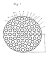
- Fig. 1 shows a cross sectional view of a cylindrical heat exchange reactor of radius R contained within a housing or pressure shell (not shown).
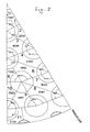
- Fig. 2 is a cross sectional view of a 30° segment of the heat exchange reactor, where only the outer diameter of the outer tube of double-tubes are shown.
- the periphery of the reactor is defined by external wall 1, which is a metallic wall, for example stainless steel.
- the interior of the reactor comprises a plurality of heat transfer tubes 2, which in principle can have any shape, but are preferably cylindrical, i.e. with a circular cross section.
- the space in between heat transfer tubes 2 comprises catalyst particles forming catalyst bed 3.
- said heat transfer tubes 2 are double-tubes, their inner tubes are filled with solid catalyst particles 3'.
- the heat transfer tubes 2 are arranged so as to provide for a uniform distribution of heat and thereby uniform temperature throughout the whole cross-section of the reactor.
- a plurality of built-in elements, here peripheral heat transfer tubes 4 providing additional heat exchanging area and reducing the amount of catalyst near the external reactor wall 1 are placed near or in direct contact with said wall 1 and allow the passage of a heat exchanging medium 5 in counter-current with process gas 6.
- Process gas 6 for instance a gas mixture containing methane as the chief component, travels through the catalyst in a direction transverse to plane of the sheet of paper and is cooled or heated indirectly by heat exchanging medium 5 passing counter-currently with process gas 6 through the annular space created in between the walls of heat transfer tubes 2.
- Peripheral heat transfer tubes 4 can have any shape but are preferably simple tubes with substantially semi-circular or substantially triangular so that their flatter region is able to fit with the curvature of the external reactor wall 1. Said peripheral heat transfer tubes 4 can be fitted to external reactor wall 1 by suitable anchoring means allowing for differential thermal expansion.
- the cross-section of peripheral heat transfer tubes 4 has a major axis d 1 and minor axis d 2 , whereby said major axis d 1 defines the flatter region that is able to fit with the curvature of the external reactor wall 1.
- the peripheral heat transfer tubes 4 are in direct contact with the external wall 1.
- a minimum radial distance d is provided between external reactor wall 1 and the outermost wall of the outermost heat transfer tubes 2, so that solid catalyst particles 3 are able to surround the entire outer surface of said heat transfer tubes 2.
- peripheral heat transfer tubes 4 and heat transfer tubes 2 corresponds roughly to the length of the reactor, the length of the peripheral tubes being in the range 6 to 14 m.
- the thickness of the peripheral tubes is normally in the range 3-8 mm, while the heat transfer tubes, here represented by double-tubes, normally have an inner wall thickness of 2-6 mm and outer wall thickness of 3-8 mm.
- the annular spacing for the passage of heat exchanging medium 5 in the double tube is not more than about 4 to 12 mm.
- Fig. 2 the layout of double-tubes shown is a 30° segment which can be mirrored to a 60° segment. This 60° section is repeated to form the full 360° tube layout.
- the area outside the tubes containing catalyst can be divided into sub-areas limited by lines drawn from double tube centre to double tube centre. All such areas containing catalyst receive heat from three outer tubes, each tube contributing with a heat transfer surface that corresponds to 60° of the tube perimeter, thus constituting a total heat transfer surface equal to half the circumference of an outer tube (180°).
- the locations denoted 1, 2, 6 and 10 are shown in half only and need to be mirrored (mirror line is the free side) to give the full shape and size of that particular location.
- the heat transfer tubes are preferably arranged in a triangular pitch, where the minimum distance from double tube center to double tube center is about 143 mm. This results in a distance of about 29 mm between outer tubes of neighboring double tubes, which gives ample space for catalyst particles to fill the gap.
- the catalyst areas of the various locations were calculated. Location 1 with the smallest area of 3774 mm 2 (2 x 1887 mm 2 ) is best supplied with heat, while location 10 having the largest area of 5304 mm 2 (2 x 2652 mm 2 ) has the poorest heat supply. For the two locations above the ratios of catalyst area to heat surface, defined by the catalyst area divided by outer perimeter of outer tubes, become 21.0 mm 2 /mm and 29.5 mm 2 /mm, respectively. During reactor operation, however, there will be some mixing of gas and horizontal heat transfer across the borders of the numbered areas, which will tend to lower the effect of the difference in catalyst area to heat surface ratio for the different locations.
- the values marked with * include heat transfer surface from peripheral heat transfer tubes having a triangular cross-section. Only the area in contact with the catalyst has been counted.
- the variation in catalyst area to heat surface is found satisfactory low.
- the inner ring (No. 1) is over supplied with heat but only constitutes 3.7% of the total catalyst area.
- the heat transfer surface in the outer ring (No. 5) is greater than the average heat transfer surface. Without the peripheral heat transfer tubes, the total catalyst area in the catalyst ring becomes 171178 mm 2 , while the total heat surface perimeter in the ring is 4668 mm. A high value of the ratio of catalyst area to heat surface is obtained: 36.7 mm.
- the invention is particularly useful for the steam reforming of hydrocarbon feedstocks comprising methane by means of heat supplied from hot effluent gas from an autothermal reforming reactor placed downstream the heat exchanging reactor and steam reformed product gas from the process.
- the hot effluent gas from the autothermal reforming reactor having a temperature of about 1050°C is combined with the converted process gas in the heat exchanging reactor of the invention, which leaves the catalyst beds at the bottom of the reactor at about 880°C.
- the combined gas is used for the indirect heating of the catalyst beds disposed outside the heat transfer tubes of the reactor layout by letting pass said combined gas upwardly through the heat transfer tubes as well as through the peripheral heat transfer tubes, which are positioned near or at the external reactor wall and in parallel with the heat transfer tubes.
- the combined gas is cooled from about 1000°C to about 650°C at which temperature it leaves the reactor and is removed as a hydrogen-rich synthesis gas stream for further processing.
- the invention also encompasses a process for the steam reforming of hydrocarbon feedstocks comprising:
Landscapes
- Chemical & Material Sciences (AREA)
- Chemical Kinetics & Catalysis (AREA)
- Organic Chemistry (AREA)
- Physics & Mathematics (AREA)
- Fluid Mechanics (AREA)
- General Health & Medical Sciences (AREA)
- Health & Medical Sciences (AREA)
- Engineering & Computer Science (AREA)
- Combustion & Propulsion (AREA)
- Inorganic Chemistry (AREA)
- Devices And Processes Conducted In The Presence Of Fluids And Solid Particles (AREA)
- Hydrogen, Water And Hydrids (AREA)
- Physical Or Chemical Processes And Apparatus (AREA)
Claims (6)
- Réacteur d'échange de chaleur pour effectuer des réactions endothermiques ou exothermiques, comprenant:un carter définissant une paroi externe du réacteur (1),une pluralité de tubes de transfert de chaleur (2) agencés à l'intérieur dudit carter pour la fourniture ou l'évacuation de la chaleur dans des lits catalytiques (3, 3') disposés au moins à l'extérieur (3) desdits tubes de transfert de chaleur (2), et des éléments intégrés (4) qui servent à créer un rapport surface catalytique/surface de transfert de chaleur dans la périphérie extérieure du lit catalytique similaire à celui qui est obtenu dans la section transversale de lit restante, et qui sont des éléments allongés s'étendant parallèlement aux tubes de transfert de chaleur etsont disposés dans la périphérie extérieure dudit lit catalytique (3), dans lequel lesdits éléments intégrés sont des tubes de transfert de chaleur périphériques à travers lesquels passe un moyen d'échange de chaleur et ledit moyen d'échange de chaleur est un fluide gazeux circulant à co-courant ou à contre-courant du flux de gaz de traitement passant à travers ledit lit catalytique, et dans lequel les éléments intégrés (4) sont placés en contact direct avec la paroi externe du réacteur (1).
- Réacteur selon la revendication 1, dans lequel les tubes de transfert de chaleur (2) sont des tubes doubles de sorte que les particules solides formant les lits catalytiques (3, 3') sont disposées à la fois à l'extérieur (3) des tubes de transfert de chaleur (2) et à l'intérieur (3') desdits tubes de transfert de chaleur (2).
- Réacteur selon la revendication 1, dans lequel les particules solides formant le lit catalytique se présentent sous la forme d'un lit catalytique à l'extérieur (3) des tubes de transfert de chaleur (2), mais pas à l'intérieur (3') des tubes de transfert de chaleur (2).
- Réacteur selon l'une quelconque des revendications précédentes, dans lequel les éléments intégrés (4) ont une forme sensiblement triangulaire ou semi-circulaire en coupe.
- Procédé de reformage à la vapeur de charges d'hydrocarbures, consistant à : (a) former un gaz combiné (5) dans un réacteur d'échange de chaleur selon la revendication 1 en combinant l'effluent gazeux chaud provenant d'un reformeur autothermique avec le gaz de traitement converti (6) quittant les lits catalytiques (3, 3') disposés au moins à l'extérieur des tubes de transfert de chaleur (2) dudit réacteur, (b) faire passer ledit gaz combiné (5) à travers l'espace annulaire desdits tubes de transfert de chaleur pour le chauffage indirect desdits lits catalytiques (3, 3'), (c) extraire ledit gaz combiné (5) du réacteur d'échange de chaleur sous la forme d'un flux de gaz de synthèse riche en hydrogène, dans lequel le réacteur d'échange de chaleur comprend des tubes de transfert de chaleur périphériques (4) placés en contact direct avec la paroi externe du réacteur (1) et qui servent à créer un rapport surface catalytique/surface de transfert de chaleur dans la périphérie extérieure du lit catalytique similaire à celui qui est obtenu dans la section transversale de lit restante, et le gaz combiné (5) de l'étape (a) est conduit à travers lesdits tubes de transfert de chaleur périphériques (4) positionnés parallèlement aux tubes de transfert de chaleur (2).
- Procédé selon la revendication 5, dans lequel les tubes de transfert de chaleur (2) sont des tubes doubles et le gaz combiné (5) est conduit à travers l'espace annulaire desdits tubes doubles.
Priority Applications (1)
| Application Number | Priority Date | Filing Date | Title |
|---|---|---|---|
| PL05803822T PL1807190T3 (pl) | 2004-10-26 | 2005-10-14 | Reaktor i sposób prowadzenia endotermicznych lub egzotermicznych reakcji katalitycznych |
Applications Claiming Priority (2)
| Application Number | Priority Date | Filing Date | Title |
|---|---|---|---|
| DKPA200401635 | 2004-10-26 | ||
| PCT/EP2005/011076 WO2006045457A1 (fr) | 2004-10-26 | 2005-10-14 | Reacteur et procede de realisation de reactions catalytiques endothermiques ou exothermiques |
Publications (2)
| Publication Number | Publication Date |
|---|---|
| EP1807190A1 EP1807190A1 (fr) | 2007-07-18 |
| EP1807190B1 true EP1807190B1 (fr) | 2013-05-15 |
Family
ID=35645710
Family Applications (1)
| Application Number | Title | Priority Date | Filing Date |
|---|---|---|---|
| EP05803822.5A Expired - Lifetime EP1807190B1 (fr) | 2004-10-26 | 2005-10-14 | Reacteur et procede de realisation de reactions catalytiques endothermiques ou exothermiques |
Country Status (13)
| Country | Link |
|---|---|
| US (1) | US7776285B2 (fr) |
| EP (1) | EP1807190B1 (fr) |
| JP (1) | JP2008517864A (fr) |
| KR (1) | KR101252493B1 (fr) |
| CN (1) | CN101060920B (fr) |
| AR (1) | AR052118A1 (fr) |
| CA (1) | CA2585028C (fr) |
| ES (1) | ES2416331T3 (fr) |
| MX (1) | MX2007004754A (fr) |
| PL (1) | PL1807190T3 (fr) |
| RU (1) | RU2379100C2 (fr) |
| WO (1) | WO2006045457A1 (fr) |
| ZA (1) | ZA200704300B (fr) |
Families Citing this family (3)
| Publication number | Priority date | Publication date | Assignee | Title |
|---|---|---|---|---|
| US9683474B2 (en) * | 2013-08-30 | 2017-06-20 | Dürr Systems Inc. | Block channel geometries and arrangements of thermal oxidizers |
| FR3057654B1 (fr) * | 2016-10-14 | 2019-06-28 | Axens | Dispositif de refroidissement d'un solide caloporteur destine a en controler precisement la temperature, le dit dispositif pouvant etre associe a un procede endothermique ou exothermique. |
| KR101982786B1 (ko) * | 2017-12-01 | 2019-05-28 | 한국에너지기술연구원 | 유동층 반응기 |
Family Cites Families (21)
| Publication number | Priority date | Publication date | Assignee | Title |
|---|---|---|---|---|
| ES183753Y (es) * | 1969-01-15 | 1974-08-16 | Un elemento de reactor para la conservacion de hidrocarbu- ros. | |
| US3980440A (en) * | 1975-08-06 | 1976-09-14 | General Atomic Company | Catalyst tube assembly for steam-hydrocarbon reformer |
| JPS5839572B2 (ja) * | 1979-04-03 | 1983-08-31 | 東洋エンジニアリング株式会社 | 反応器およびその使用法 |
| US4743432A (en) * | 1984-11-16 | 1988-05-10 | M.A.N. Maschinenfabrik Augsburg-Nurnberg | Vertical reactor for the generation of methanol |
| JPS61285389A (ja) * | 1985-06-12 | 1986-12-16 | Toshiba Corp | 熱交換器 |
| DE3532413A1 (de) * | 1985-09-11 | 1987-03-12 | Uhde Gmbh | Vorrichtung zur erzeugung von synthesegas |
| GB8629497D0 (en) * | 1986-12-10 | 1987-01-21 | British Petroleum Co Plc | Apparatus |
| DK167242B1 (da) | 1989-02-16 | 1993-09-27 | Topsoe Haldor As | Apparat og fremgangsmaade til exoterme reaktioner |
| DE4221837C1 (en) * | 1992-07-03 | 1993-08-19 | Uhde Gmbh, 4600 Dortmund, De | Shrouded catalytic reformer tube - with partially enclosed gas mixing zone, for prodn. of synthesis gas |
| US5520891A (en) * | 1994-02-01 | 1996-05-28 | Lee; Jing M. | Cross-flow, fixed-bed catalytic reactor |
| US5869011A (en) * | 1994-02-01 | 1999-02-09 | Lee; Jing Ming | Fixed-bed catalytic reactor |
| RU2136369C1 (ru) * | 1996-07-02 | 1999-09-10 | Акционерное общество открытого типа "Всероссийский алюминиево-магниевый институт" | Способ получения алюминиевой пудры |
| WO2002002220A1 (fr) * | 2000-06-29 | 2002-01-10 | H2Gen Innovations Inc. | Systeme ameliore et reacteur chimique integre permettant de produire de l'hydrogene par reformage de vapeur d'hydrocarbures |
| JP2002246055A (ja) * | 2001-02-15 | 2002-08-30 | Daikin Ind Ltd | 一酸化炭素除去器及び燃料電池 |
| US6855272B2 (en) * | 2001-07-18 | 2005-02-15 | Kellogg Brown & Root, Inc. | Low pressure drop reforming exchanger |
| JP4136497B2 (ja) * | 2002-07-02 | 2008-08-20 | トヨタ自動車株式会社 | 水蒸気混合装置および燃料改質装置 |
| GB0301323D0 (en) * | 2003-01-21 | 2003-02-19 | Johnson Matthey Plc | Methanol synthesis |
| JP4033402B2 (ja) * | 2004-04-27 | 2008-01-16 | 本田技研工業株式会社 | 熱交換器 |
| EP1600209B1 (fr) * | 2004-05-29 | 2024-08-21 | Topsoe A/S | Réacteur avec échange de chaleur |
| JP4477432B2 (ja) * | 2004-06-29 | 2010-06-09 | 東洋エンジニアリング株式会社 | 改質器 |
| US20070000172A1 (en) * | 2005-06-28 | 2007-01-04 | Michael Boe | Compact reforming reactor |
-
2005
- 2005-10-14 WO PCT/EP2005/011076 patent/WO2006045457A1/fr not_active Ceased
- 2005-10-14 ZA ZA200704300A patent/ZA200704300B/xx unknown
- 2005-10-14 MX MX2007004754A patent/MX2007004754A/es active IP Right Grant
- 2005-10-14 CN CN2005800365476A patent/CN101060920B/zh not_active Expired - Fee Related
- 2005-10-14 CA CA2585028A patent/CA2585028C/fr not_active Expired - Fee Related
- 2005-10-14 EP EP05803822.5A patent/EP1807190B1/fr not_active Expired - Lifetime
- 2005-10-14 JP JP2007538295A patent/JP2008517864A/ja active Pending
- 2005-10-14 KR KR1020077011573A patent/KR101252493B1/ko not_active Expired - Lifetime
- 2005-10-14 RU RU2007119438/12A patent/RU2379100C2/ru active
- 2005-10-14 US US11/666,279 patent/US7776285B2/en active Active
- 2005-10-14 ES ES05803822T patent/ES2416331T3/es not_active Expired - Lifetime
- 2005-10-14 PL PL05803822T patent/PL1807190T3/pl unknown
- 2005-10-26 AR ARP050104476A patent/AR052118A1/es not_active Application Discontinuation
Also Published As
| Publication number | Publication date |
|---|---|
| ZA200704300B (en) | 2008-09-25 |
| US7776285B2 (en) | 2010-08-17 |
| CN101060920B (zh) | 2010-12-08 |
| AR052118A1 (es) | 2007-03-07 |
| RU2379100C2 (ru) | 2010-01-20 |
| CN101060920A (zh) | 2007-10-24 |
| KR101252493B1 (ko) | 2013-04-09 |
| PL1807190T3 (pl) | 2013-10-31 |
| KR20070084451A (ko) | 2007-08-24 |
| ES2416331T3 (es) | 2013-07-31 |
| WO2006045457A1 (fr) | 2006-05-04 |
| CA2585028C (fr) | 2013-07-23 |
| EP1807190A1 (fr) | 2007-07-18 |
| CA2585028A1 (fr) | 2006-05-04 |
| MX2007004754A (es) | 2007-05-11 |
| JP2008517864A (ja) | 2008-05-29 |
| RU2007119438A (ru) | 2008-12-10 |
| US20070255082A1 (en) | 2007-11-01 |
Similar Documents
| Publication | Publication Date | Title |
|---|---|---|
| EP1277698B1 (fr) | Dispositif de reformage à échange de chaleur à faible perte de pression | |
| EP2249954B1 (fr) | Réacteur catalytique | |
| CN102316971B (zh) | 制备光气的反应器和方法 | |
| US5869011A (en) | Fixed-bed catalytic reactor | |
| AU2018387802B2 (en) | Method and reactor for performing exothermic reactions | |
| EP2526044B1 (fr) | Procédé pour le reformage d'hydrocarbures | |
| EP1403215B1 (fr) | Procédé et appareil pour la production de gas de synthèse | |
| EP1600209A1 (fr) | Procédé et réacteur avec échange de chaleur | |
| CN102316970A (zh) | 制备光气的反应器和方法 | |
| KR101015876B1 (ko) | 합성가스의 제조 방법 및 장치 | |
| TWI281458B (en) | Process and reactor for the preparation of ammonia | |
| AU2001224509A1 (en) | Simplified plate channel reactor arrangement | |
| WO2003031050A1 (fr) | Reacteur echangeur de chaleur | |
| EP1807190B1 (fr) | Reacteur et procede de realisation de reactions catalytiques endothermiques ou exothermiques | |
| US11731097B2 (en) | Catalyst particle shape | |
| CA2590411C (fr) | Reacteur pour reaction de conversion catalytique | |
| EP1707259B1 (fr) | Procédé pour la synthèse hétérogène de composés chimiques | |
| JPH0150452B2 (fr) | ||
| JPS63123433A (ja) | 反応器 | |
| KR20220065027A (ko) | 반응기 튜브 조립체 | |
| JPH06172760A (ja) | 多段冷却型ガス反応装置 | |
| BR112020012389B1 (pt) | Conversor de fluxo axial adiabático | |
| ZA200305320B (en) | Simplified plate channel reactor arrangement. |
Legal Events
| Date | Code | Title | Description |
|---|---|---|---|
| PUAI | Public reference made under article 153(3) epc to a published international application that has entered the european phase |
Free format text: ORIGINAL CODE: 0009012 |
|
| 17P | Request for examination filed |
Effective date: 20070529 |
|
| AK | Designated contracting states |
Kind code of ref document: A1 Designated state(s): AT BE BG CH CY CZ DE DK EE ES FI FR GB GR HU IE IS IT LI LT LU LV MC NL PL PT RO SE SI SK TR |
|
| DAX | Request for extension of the european patent (deleted) | ||
| 17Q | First examination report despatched |
Effective date: 20110202 |
|
| GRAP | Despatch of communication of intention to grant a patent |
Free format text: ORIGINAL CODE: EPIDOSNIGR1 |
|
| GRAS | Grant fee paid |
Free format text: ORIGINAL CODE: EPIDOSNIGR3 |
|
| GRAA | (expected) grant |
Free format text: ORIGINAL CODE: 0009210 |
|
| AK | Designated contracting states |
Kind code of ref document: B1 Designated state(s): AT BE BG CH CY CZ DE DK EE ES FI FR GB GR HU IE IS IT LI LT LU LV MC NL PL PT RO SE SI SK TR |
|
| REG | Reference to a national code |
Ref country code: CH Ref legal event code: EP Ref country code: GB Ref legal event code: FG4D |
|
| REG | Reference to a national code |
Ref country code: AT Ref legal event code: REF Ref document number: 611845 Country of ref document: AT Kind code of ref document: T Effective date: 20130615 |
|
| REG | Reference to a national code |
Ref country code: IE Ref legal event code: FG4D |
|
| REG | Reference to a national code |
Ref country code: DE Ref legal event code: R096 Ref document number: 602005039615 Country of ref document: DE Effective date: 20130711 |
|
| REG | Reference to a national code |
Ref country code: RO Ref legal event code: EPE |
|
| REG | Reference to a national code |
Ref country code: NL Ref legal event code: T3 |
|
| REG | Reference to a national code |
Ref country code: AT Ref legal event code: MK05 Ref document number: 611845 Country of ref document: AT Kind code of ref document: T Effective date: 20130515 |
|
| REG | Reference to a national code |
Ref country code: LT Ref legal event code: MG4D |
|
| PG25 | Lapsed in a contracting state [announced via postgrant information from national office to epo] |
Ref country code: IS Free format text: LAPSE BECAUSE OF FAILURE TO SUBMIT A TRANSLATION OF THE DESCRIPTION OR TO PAY THE FEE WITHIN THE PRESCRIBED TIME-LIMIT Effective date: 20130915 Ref country code: SE Free format text: LAPSE BECAUSE OF FAILURE TO SUBMIT A TRANSLATION OF THE DESCRIPTION OR TO PAY THE FEE WITHIN THE PRESCRIBED TIME-LIMIT Effective date: 20130515 Ref country code: SI Free format text: LAPSE BECAUSE OF FAILURE TO SUBMIT A TRANSLATION OF THE DESCRIPTION OR TO PAY THE FEE WITHIN THE PRESCRIBED TIME-LIMIT Effective date: 20130515 Ref country code: PT Free format text: LAPSE BECAUSE OF FAILURE TO SUBMIT A TRANSLATION OF THE DESCRIPTION OR TO PAY THE FEE WITHIN THE PRESCRIBED TIME-LIMIT Effective date: 20130916 Ref country code: GR Free format text: LAPSE BECAUSE OF FAILURE TO SUBMIT A TRANSLATION OF THE DESCRIPTION OR TO PAY THE FEE WITHIN THE PRESCRIBED TIME-LIMIT Effective date: 20130816 Ref country code: AT Free format text: LAPSE BECAUSE OF FAILURE TO SUBMIT A TRANSLATION OF THE DESCRIPTION OR TO PAY THE FEE WITHIN THE PRESCRIBED TIME-LIMIT Effective date: 20130515 Ref country code: FI Free format text: LAPSE BECAUSE OF FAILURE TO SUBMIT A TRANSLATION OF THE DESCRIPTION OR TO PAY THE FEE WITHIN THE PRESCRIBED TIME-LIMIT Effective date: 20130515 Ref country code: LT Free format text: LAPSE BECAUSE OF FAILURE TO SUBMIT A TRANSLATION OF THE DESCRIPTION OR TO PAY THE FEE WITHIN THE PRESCRIBED TIME-LIMIT Effective date: 20130515 |
|
| REG | Reference to a national code |
Ref country code: PL Ref legal event code: T3 |
|
| PG25 | Lapsed in a contracting state [announced via postgrant information from national office to epo] |
Ref country code: BG Free format text: LAPSE BECAUSE OF FAILURE TO SUBMIT A TRANSLATION OF THE DESCRIPTION OR TO PAY THE FEE WITHIN THE PRESCRIBED TIME-LIMIT Effective date: 20130815 |
|
| PG25 | Lapsed in a contracting state [announced via postgrant information from national office to epo] |
Ref country code: LV Free format text: LAPSE BECAUSE OF FAILURE TO SUBMIT A TRANSLATION OF THE DESCRIPTION OR TO PAY THE FEE WITHIN THE PRESCRIBED TIME-LIMIT Effective date: 20130515 |
|
| PG25 | Lapsed in a contracting state [announced via postgrant information from national office to epo] |
Ref country code: DK Free format text: LAPSE BECAUSE OF FAILURE TO SUBMIT A TRANSLATION OF THE DESCRIPTION OR TO PAY THE FEE WITHIN THE PRESCRIBED TIME-LIMIT Effective date: 20130515 Ref country code: EE Free format text: LAPSE BECAUSE OF FAILURE TO SUBMIT A TRANSLATION OF THE DESCRIPTION OR TO PAY THE FEE WITHIN THE PRESCRIBED TIME-LIMIT Effective date: 20130515 Ref country code: BE Free format text: LAPSE BECAUSE OF FAILURE TO SUBMIT A TRANSLATION OF THE DESCRIPTION OR TO PAY THE FEE WITHIN THE PRESCRIBED TIME-LIMIT Effective date: 20130515 Ref country code: SK Free format text: LAPSE BECAUSE OF FAILURE TO SUBMIT A TRANSLATION OF THE DESCRIPTION OR TO PAY THE FEE WITHIN THE PRESCRIBED TIME-LIMIT Effective date: 20130515 |
|
| PLBE | No opposition filed within time limit |
Free format text: ORIGINAL CODE: 0009261 |
|
| STAA | Information on the status of an ep patent application or granted ep patent |
Free format text: STATUS: NO OPPOSITION FILED WITHIN TIME LIMIT |
|
| 26N | No opposition filed |
Effective date: 20140218 |
|
| REG | Reference to a national code |
Ref country code: DE Ref legal event code: R097 Ref document number: 602005039615 Country of ref document: DE Effective date: 20140218 |
|
| PG25 | Lapsed in a contracting state [announced via postgrant information from national office to epo] |
Ref country code: MC Free format text: LAPSE BECAUSE OF FAILURE TO SUBMIT A TRANSLATION OF THE DESCRIPTION OR TO PAY THE FEE WITHIN THE PRESCRIBED TIME-LIMIT Effective date: 20130515 |
|
| REG | Reference to a national code |
Ref country code: IE Ref legal event code: MM4A |
|
| PG25 | Lapsed in a contracting state [announced via postgrant information from national office to epo] |
Ref country code: IE Free format text: LAPSE BECAUSE OF NON-PAYMENT OF DUE FEES Effective date: 20131014 |
|
| PGFP | Annual fee paid to national office [announced via postgrant information from national office to epo] |
Ref country code: CH Payment date: 20141027 Year of fee payment: 10 Ref country code: ES Payment date: 20141027 Year of fee payment: 10 Ref country code: FR Payment date: 20141017 Year of fee payment: 10 |
|
| PGFP | Annual fee paid to national office [announced via postgrant information from national office to epo] |
Ref country code: NL Payment date: 20141026 Year of fee payment: 10 |
|
| PG25 | Lapsed in a contracting state [announced via postgrant information from national office to epo] |
Ref country code: CY Free format text: LAPSE BECAUSE OF FAILURE TO SUBMIT A TRANSLATION OF THE DESCRIPTION OR TO PAY THE FEE WITHIN THE PRESCRIBED TIME-LIMIT Effective date: 20130515 Ref country code: TR Free format text: LAPSE BECAUSE OF FAILURE TO SUBMIT A TRANSLATION OF THE DESCRIPTION OR TO PAY THE FEE WITHIN THE PRESCRIBED TIME-LIMIT Effective date: 20130515 |
|
| PG25 | Lapsed in a contracting state [announced via postgrant information from national office to epo] |
Ref country code: HU Free format text: LAPSE BECAUSE OF FAILURE TO SUBMIT A TRANSLATION OF THE DESCRIPTION OR TO PAY THE FEE WITHIN THE PRESCRIBED TIME-LIMIT; INVALID AB INITIO Effective date: 20051014 Ref country code: LU Free format text: LAPSE BECAUSE OF NON-PAYMENT OF DUE FEES Effective date: 20131014 |
|
| PGFP | Annual fee paid to national office [announced via postgrant information from national office to epo] |
Ref country code: CZ Payment date: 20150924 Year of fee payment: 11 Ref country code: RO Payment date: 20150922 Year of fee payment: 11 |
|
| REG | Reference to a national code |
Ref country code: CH Ref legal event code: PL |
|
| REG | Reference to a national code |
Ref country code: NL Ref legal event code: MM Effective date: 20151101 |
|
| PG25 | Lapsed in a contracting state [announced via postgrant information from national office to epo] |
Ref country code: CH Free format text: LAPSE BECAUSE OF NON-PAYMENT OF DUE FEES Effective date: 20151031 Ref country code: LI Free format text: LAPSE BECAUSE OF NON-PAYMENT OF DUE FEES Effective date: 20151031 |
|
| REG | Reference to a national code |
Ref country code: FR Ref legal event code: ST Effective date: 20160630 |
|
| PG25 | Lapsed in a contracting state [announced via postgrant information from national office to epo] |
Ref country code: FR Free format text: LAPSE BECAUSE OF NON-PAYMENT OF DUE FEES Effective date: 20151102 Ref country code: NL Free format text: LAPSE BECAUSE OF NON-PAYMENT OF DUE FEES Effective date: 20151101 |
|
| REG | Reference to a national code |
Ref country code: ES Ref legal event code: FD2A Effective date: 20161125 |
|
| PG25 | Lapsed in a contracting state [announced via postgrant information from national office to epo] |
Ref country code: ES Free format text: LAPSE BECAUSE OF NON-PAYMENT OF DUE FEES Effective date: 20151015 |
|
| PG25 | Lapsed in a contracting state [announced via postgrant information from national office to epo] |
Ref country code: CZ Free format text: LAPSE BECAUSE OF NON-PAYMENT OF DUE FEES Effective date: 20161014 Ref country code: RO Free format text: LAPSE BECAUSE OF NON-PAYMENT OF DUE FEES Effective date: 20161014 |
|
| PGFP | Annual fee paid to national office [announced via postgrant information from national office to epo] |
Ref country code: PL Payment date: 20211001 Year of fee payment: 17 |
|
| P01 | Opt-out of the competence of the unified patent court (upc) registered |
Effective date: 20230602 |
|
| PG25 | Lapsed in a contracting state [announced via postgrant information from national office to epo] |
Ref country code: PL Free format text: LAPSE BECAUSE OF NON-PAYMENT OF DUE FEES Effective date: 20221014 |
|
| PGFP | Annual fee paid to national office [announced via postgrant information from national office to epo] |
Ref country code: DE Payment date: 20241029 Year of fee payment: 20 |
|
| PGFP | Annual fee paid to national office [announced via postgrant information from national office to epo] |
Ref country code: GB Payment date: 20241022 Year of fee payment: 20 |
|
| PGFP | Annual fee paid to national office [announced via postgrant information from national office to epo] |
Ref country code: IT Payment date: 20241022 Year of fee payment: 20 |
|
| REG | Reference to a national code |
Ref country code: DE Ref legal event code: R071 Ref document number: 602005039615 Country of ref document: DE |
|
| REG | Reference to a national code |
Ref country code: GB Ref legal event code: PE20 Expiry date: 20251013 |